
CNC lathes are among the most widely used machine tools in modern manufacturing, forming the backbone of cylindrical component production across industries ranging from automotive to aerospace. By rotating the workpiece against a stationary cutting tool, a CNC lathe removes material with high precision to produce shafts, fittings, connectors, and a broad range of rotational parts.
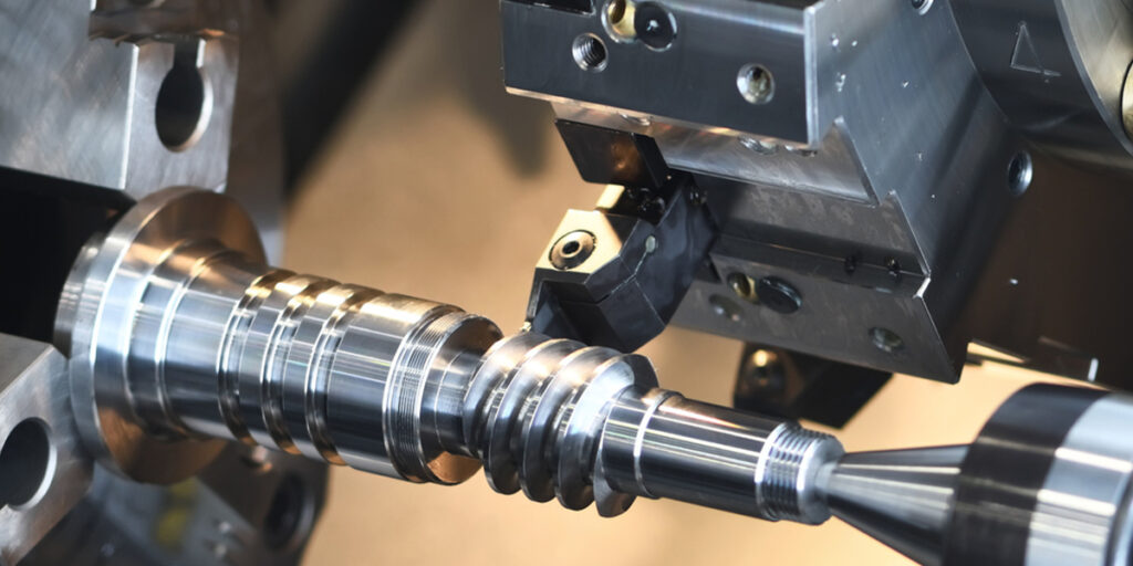
Four operations define the core capability of a CNC lathe: facing, turning, threading, and grooving. Each serves a distinct purpose, yet in practice, they are rarely performed in isolation. A single part, such as a hydraulic connector or a motor shaft, typically requires all four operations executed in a planned sequence within one setup. Understanding each operation individually and how they work together is fundamental to effective CNC lathe process planning and part quality.
Understanding CNC Lathe Machining Fundamentals
CNC lathe machining is the starting point for understanding how cylindrical components are produced to tight dimensional specifications. Before examining individual operations, it is worth establishing what a CNC lathe is, how it functions mechanically, and why lathe operations remain central to precision manufacturing despite the availability of more complex multi-axis machining technologies.
What Is CNC Lathe Machining?
A CNC lathe is a computer-controlled machine tool that rotates a workpiece about its central axis while a cutting tool moves along programmed paths to remove material and generate the desired geometry. The fundamental principle distinguishes lathes from milling machines: on a lathe, the workpiece rotates and the tool is nominally stationary in rotation, whereas on a milling machine, the tool rotates and the workpiece remains fixed. This distinction makes lathes inherently suited to producing cylindrical, conical, and rotationally symmetric geometries with high accuracy and surface quality.
The CNC controller interprets a part program, typically written in G-code, and converts it into coordinated motion of the machine axes, spindle speed, and tool selection. This eliminates the manual adjustments required on conventional lathes and delivers repeatable results across production batches without operator-to-operator variation. [1]
Main Components of a CNC Lathe
Understanding the functional role of each machine component clarifies how the operations discussed in subsequent sections are physically executed:
- Chuck: Clamps and rotates the workpiece. Three-jaw chucks are standard for round stock, while four-jaw chucks allow precise centering of irregular workpieces.
- Spindle: The rotating assembly that drives the chuck and workpiece. Spindle speed is programmable and adjusts automatically as cutting conditions change.
- Tool turret: Holds multiple cutting tools simultaneously and indexes to the correct tool position under program control, eliminating manual tool changes and reducing cycle time.
- Tailstock: Provides axial support at the free end of long workpieces using a live or dead center, preventing deflection under cutting forces.
- CNC controller: The machine's computing unit that executes the part program, manages axis motion, monitors cutting conditions, and handles tool offset compensation.
Why Lathe Operations Matter
CNC lathe operations deliver three manufacturing advantages that are difficult to replicate through alternative processes:
- Accuracy and repeatability: Modern CNC lathes hold diameter tolerances of ±0.005 mm or better in production conditions, with positional repeatability that ensures every part in a batch meets the same specification.
- Faster production: Automated tool changes, constant surface speed control, and programmed multi-pass cycles reduce cycle times significantly compared to manual turning.
- Reduced manual intervention: Once a program is validated, operator involvement is limited to workpiece loading, periodic measurement, and tool wear monitoring, reducing the risk of human error in high-volume production.
A practical illustration of these advantages is the production of a hydraulic shaft requiring facing, turning, threading, and grooving. All four operations are completed in a single setup on a CNC lathe, maintaining a common datum throughout and eliminating the repositioning errors that would accumulate if the part were moved between machines. [2]
CNC Facing Operation
Facing is typically the first operation performed on a CNC lathe and sets the dimensional and geometric foundation for every subsequent operation. A workpiece that has not been properly faced will carry length inaccuracies and surface irregularities that propagate through the entire machining sequence. Despite being one of the simpler lathe operations in concept, facing has a direct influence on the accuracy of the finished part.

The Facing Operation In Machining
What Is Facing?
Facing is a lathe operation in which the cutting tool moves radially across the end face of a rotating workpiece, removing material to produce a flat, smooth surface perpendicular to the spindle axis. The primary purpose is to establish a clean, accurate reference surface at the end of the workpiece from which axial dimensions can be measured and controlled throughout subsequent operations. On raw stock material, end faces are rarely flat or square; facing corrects this before any further machining is attempted.
How Facing Works
The workpiece is clamped in the chuck and rotated at a programmed spindle speed. The cutting tool is positioned at the outer diameter of the workpiece and fed radially inward toward the center at a controlled feed rate. The tool removes a thin layer of material across the entire face in a single pass or multiple passes, depending on the stock condition and the required surface finish. Constant surface speed control is typically applied during facing, as the cutting speed would otherwise decrease as the tool approaches the center of the workpiece, where the surface velocity is lower. [3]
Tool selection for facing generally favors 80-degree diamond or trigon inserts mounted in a right-hand tool holder, providing sufficient clearance for the radial feed direction while maintaining edge strength.
Benefits of Facing
- Creates flat and smooth surfaces: A properly faced end provides a geometrically reliable surface for subsequent measurements, component seating, or tailstock center drilling.
- Establishes accurate workpiece length: Facing removes excess stock from the workpiece end to bring it to the correct starting length before diameter turning begins.
- Improves dimensional consistency: In batch production, consistent facing ensures that all workpieces start from the same axial reference, reducing length variation across the batch.
Common Applications
Facing is applied across a wide range of production scenarios:
- Preparing raw stock: Bar stock cut from a saw typically has rough, slightly angled end faces. Facing squares and smooth these faces before further machining.
- Creating reference surfaces: Faced ends serve as datum surfaces for axial measurements during turning, threading, and grooving operations.
- Finishing shaft ends: On completed shafts, facing produces the clean end faces required for proper component seating and assembly fit.
Best Practices
- Feed rate selection: Facing feed rates typically range from 0.05 to 0.2 mm/rev, depending on the required surface finish. Coarser feeds are acceptable for roughing passes; finishing passes require lower feeds to achieve Ra values below 1.6 µm.
- Avoiding tool chatter: Chatter during facing is most common when the tool overhang is excessive or the workpiece clamping is insufficient. Minimizing tool overhang and ensuring secure chuck clamping reduces chatter tendency significantly.
- Correct tool alignment: The cutting tool must be set precisely at the centerline height. A tool set above or below center leaves a pip of unmachined material at the workpiece center and produces a convex rather than flat face. [4]
A representative example of facing in practice is the preparation of a steel rod before turning it into a motor shaft. The raw bar end is faced to establish a clean axial datum, after which a center drill is applied at the faced surface to provide tailstock support for the turning operations that follow.
CNC Turning Operation
Turning is the defining operation of a CNC lathe and the process from which the machine takes its name. While facing addresses the end geometry of a workpiece, turning shapes the cylindrical body, reducing diameters, creating steps, generating tapers, and producing complex profiles. In shaft manufacturing specifically, turning accounts for the majority of material removal and directly determines the dimensional accuracy and surface quality of the finished component.
What Is Turning?
Turning is a material removal process in which the cutting tool moves axially along a rotating workpiece, reducing its outer diameter to a programmed target dimension. The tool engages the workpiece surface continuously as it traverses the length of the cut, generating a cylindrical surface whose diameter is determined by the radial depth of cut and whose length is determined by the axial travel of the tool. The accuracy of the resulting diameter depends on machine geometry, tool condition, cutting parameters, and workpiece rigidity, all of which must be controlled within appropriate limits to meet the specified tolerance. [5]
Types of Turning Operations
CNC turning encompasses several distinct operation types, each suited to a specific geometric requirement:
- Straight turning: The tool traverses parallel to the spindle axis at a fixed radial depth, producing a uniform cylindrical diameter along the full length of the cut. This is the most common turning operation and forms the basis of bearing seats, journal surfaces, and general cylindrical features.
- Step turning: The tool machines a series of different diameters at successive axial positions, producing a stepped profile as discussed in depth in the context of multi-diameter shaft production. Each step requires the tool to transition between a cylindrical pass and a shoulder face, demanding precise Z-axis positioning at each transition.
- Taper turning: The tool moves simultaneously in both the X and Z axes at a programmed ratio, generating a conical surface. Tapers are common on tool shanks, spindle noses, and pipe fittings where self-locking or sealing conical interfaces are required.
- Profile turning: The tool follows a complex programmed contour, producing curved or irregular axial profiles. This is used for components such as camshafts, forming rolls, and any part where the diameter varies continuously rather than in discrete steps.
Factors Affecting Turning Quality
Four primary process parameters govern the outcome of a turning operation:
- Cutting speed: Expressed in surface meters per minute, cutting speed determines the rate at which the insert edge engages the workpiece material. Too low a speed causes built-up edge formation and poor surface finish; too high a speed accelerates tool wear and risks thermal damage to the workpiece surface. For medium carbon steel, cutting speeds of 200 to 300 m/min with coated carbide inserts are representative starting conditions.
- Feed rate: Controls the axial advancement of the tool per spindle revolution. Feed rate directly influences surface roughness; lower feeds produce finer surfaces but increase cycle time. For finishing passes on bearing seats, feed rates of 0.05 to 0.1 mm/rev are typical.
- Depth of cut: Determines the radial material removed per pass. Roughing passes use depths of 2 to 5 mm to maximize material removal rate, while finishing passes use 0.1 to 0.3 mm to achieve dimensional accuracy without introducing excessive cutting forces.
- Tool material: Coated carbide is the standard choice for steel turning across roughing and finishing applications. Ceramic inserts are used for high-speed finishing of hardened materials, while CBN inserts are applied to hard turning of components above 45 HRC.
Advantages of CNC Turning
- High-dimensional accuracy: CNC turning consistently holds diameter tolerances of IT6 to IT8 in production conditions, with finishing operations capable of achieving IT5 on stable setups with well-maintained tooling.
- Excellent surface finish: Optimized finishing parameters produce Ra values of 0.4 to 1.6 µm on turned surfaces, meeting the requirements of bearing seats, seal surfaces, and journal bearings without secondary grinding in many applications.
- Efficient material removal: Roughing cycles programmed with canned cycles such as G71 automate multi-pass material removal to a defined profile, maximizing metal removal rate while maintaining a consistent finishing allowance for the subsequent finishing pass.
A practical example is the machining of a stepped transmission shaft with multiple diameters. The CNC program sequences roughing passes across the full shaft length, followed by finishing passes on each diameter zone in order of functional priority, bearing seats first, then seal surfaces, then clearance diameters, ensuring that the most critical surfaces receive the least disturbed final cut. [6]
CNC Threading Operation
Threading is one of the most technically demanding operations performed on a CNC lathe, requiring precise synchronization between spindle rotation and tool movement to generate a helical thread form that meets dimensional and functional standards. Threads are among the most common mechanical features in engineering, and the ability to produce them accurately and consistently on a CNC lathe is a core competency in precision component manufacturing.
What Is Threading?
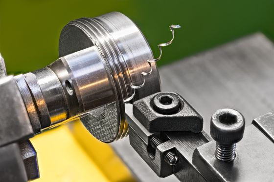
Threading is a lathe operation that cuts a helical groove of defined form and pitch onto the cylindrical surface of a workpiece. The resulting thread profile allows mechanical engagement with a mating threaded component, enabling fastening, adjustment, sealing, or power transmission depending on the application. Unlike facing or turning, where the tool feed is independent of spindle rotation, threading requires the tool to advance exactly one pitch length per spindle revolution. Any deviation in this synchronization produces a thread that is dimensionally incorrect and functionally unusable. [7]
How CNC Threading Works
On a CNC lathe, threading is achieved through rigid coupling between the spindle encoder and the Z-axis servo drive. The CNC controller reads the spindle position in real time and drives the tool carriage at a feed rate precisely equal to the programmed thread pitch. This synchronization is maintained across multiple passes, with each successive pass following the same helical path as the previous one, deepening the thread profile incrementally until the full thread depth is reached.
Key aspects of the threading process include:
- Pitch accuracy: The thread pitch must be held to the standard tolerance for the specified thread form. Pitch errors accumulate over the thread length and can prevent proper engagement with the mating component.
- Thread depth control: Threading is performed in multiple passes, with each pass removing a progressively smaller chip as the thread form deepens. This approach manages cutting forces and prevents tool deflection from distorting the thread profile.
- Infeed method: Radial infeed cuts symmetrically on both flanks of the thread form, while flank infeed cuts primarily on one flank, reducing cutting forces and improving chip control. Flank infeed is preferred for larger pitch threads and tougher materials. [8]
Types of Threads Produced
CNC lathes produce both external and internal thread forms across a wide range of standards and applications:
- External threads: Cut on the outer diameter of shafts, bolts, and connectors. Common applications include threaded shaft ends, hydraulic fittings, and fastener production. External threading is the more straightforward of the two, as tool access and chip evacuation are unconstrained.
- Internal threads: Cut inside bored holes using a threading boring bar. Internal threading is more demanding than external threading due to limited tool access, reduced rigidity of the boring bar, and the difficulty of observing and measuring the thread during cutting. Minimum bore diameter and thread depth determine the boring bar size and overhang, both of which affect achievable accuracy.
Threading Methods in CNC Lathes
Three threading methods are available on CNC lathes, each suited to different applications:
- Single-point threading: A single insert traces the helical path of the thread in multiple passes. This method is versatile, applicable to any thread form and pitch, and produces accurate threads across a wide range of materials. It is the standard method for shaft threading in precision manufacturing.
- Thread milling: While technically a milling operation, thread milling is performed on turn-mill centers and produces threads by helically interpolating a multi-tooth milling cutter. It is preferred for large-diameter threads, hard materials, and blind holes where tap breakage risk is unacceptable.
- Tapping: A tap is driven into a pre-drilled hole under CNC control to produce internal threads rapidly. Tapping is efficient for small-diameter internal threads in production volumes but is limited to standard thread forms and is sensitive to tool breakage in hard or interrupted cuts.
Key Considerations
- Thread standards: Threads must be produced to the correct standard for the application. Metric threads (ISO), Unified National Coarse (UNC), Unified National Fine (UNF), and pipe thread standards (NPT, BSPT) each have specific pitch, angle, and tolerance requirements that must be programmed and verified correctly.
- Tool wear management: Threading inserts wear progressively with each part produced. As the insert wears, thread form accuracy degrades, particularly on the flank angles and crest radius. Regular insert indexing and periodic thread gauge verification are necessary in production threading operations.
- Programming accuracy: Threading cycles such as G76 in FANUC-based controls require the correct input of pitch, thread depth, infeed angle, and number of passes. Programming errors in these parameters produce threads that appear visually acceptable but fail gauge inspection. [9]
A representative example is the production of threaded pipe fittings for industrial fluid systems. Each fitting requires external threads machined to NPT or BSPT standards, where the tapered thread form provides both mechanical engagement and pressure sealing without additional sealing components. Pitch accuracy and flank angle consistency are critical to achieving a leak-tight connection in service.
Conclusion
CNC lathe machining is built on four interdependent operations: facing, turning, threading, and grooving. Each serves a distinct geometric and functional purpose, yet none operates in isolation. Facing establishes the axial reference, turning defines the cylindrical form, and threading creates the mechanical engagement features that hold assemblies together. Executed in a planned sequence within a single setup, these operations deliver the dimensional accuracy, surface quality, and functional reliability that precision component manufacturing demands.
The value of understanding each operation individually lies in the ability to plan and optimize the complete machining sequence. Correct parameter selection, appropriate tooling, and disciplined process control at each stage are what determine whether the finished part meets its specification or requires rework. In a production environment where consistency and efficiency are equally important, mastering these four core lathe operations remains as relevant today as it has ever been.
References
Aresco, R. (2024, February 23). Erie Institute of Technology. Erie Institute of Technology. https://erieit.edu/introduction-to-cnc-turning/
Computer Numerical Control - an overview | ScienceDirect Topics. (2014). Sciencedirect.com. https://www.sciencedirect.com/topics/engineering/computer-numerical-control
Gui, G. (2025, January 11). Comprehensive Guide to Threading on a Lathe - WMT CNC Industrial Co. WMT CNC Industrial Co. https://cncwmt.com/qa/comprehensive-guide-to-threading-on-a-lathe-methods-techniques-and-step-by-step-processes/
Gui, G. (2026, January 6). How Does Face Milling Deliver Truly Flat CNC Surfaces? - WMT CNC Industrial Co. WMT CNC Industrial Co. https://cncwmt.com/qa/how-does-face-milling-deliver-truly-flat-cnc-surfaces/
Imran, M., Suo Shuangfu, Bai Yuzhu, Wang Yuming, & Naveed Raheel. (2025). Optimising subsurface integrity and surface quality in mild steel turning: A multi-objective approach to tool wear and machining parameters. Journal of Materials Research and Technology, 35, 3440–3462. https://doi.org/10.1016/j.jmrt.2025.01.246
Möhring, H.-C., Biermann, D., Bleicher, F., Melkote, S., & Kappmeyer, G. (2025). Fixtures and workpiece clamping systems in machining. CIRP Annals, 74(2), 945–969. https://doi.org/10.1016/j.cirp.2025.04.096
Omirou, S., Charalambides, M., & Chasos, C. (2024). Advanced CNC thread milling: a comprehensive canned cycle for efficient cutting of threads with fixed or variable pitch and radius. The International Journal of Advanced Manufacturing Technology, 133(5-6), 2219–2233. https://doi.org/10.1007/s00170-024-13970-5
SINHA, S. K. (2010). AUTOMATING FACING OPERATION ON A CNC MACHINING CENTRE. International Journal of Engineering Science and Technology, 2(12). https://www.researchgate.net/publication/50384400_AUTOMATING_FACING_OPERATION_ON_A_CNC_MACHINING_CENTRE
Wan, M., & Yusuf Altintas. (2014). Mechanics and dynamics of thread milling process. International Journal of Machine Tools and Manufacture, 87, 16–26. https://doi.org/10.1016/j.ijmachtools.2014.07.006