
Why Cutting-Force Direction Matters More Than Milling Preference
Climb milling vs conventional milling should be selected by cutting-force control, not by habit. The correct choice depends on machine rigidity, backlash, fixture strength, tool engagement, material behavior, surface finish requirements, and inspection risk.
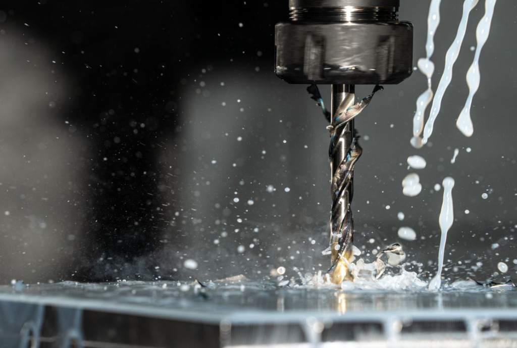
In climb milling, the cutter rotates in the same general direction as the feed at the cutting zone. In conventional milling, the cutter rotates against the feed direction. That difference changes chip thickness, cutting force direction, heat generation, tool wear, burr formation, and part stability. [2]
For BaiChuan Precision Manufacturing, the central engineering question is not “Which method is better?” The better question is: which milling direction best controls force, rigidity, surface quality, and dimensional risk for this specific part?
The strongest milling strategy is the one that keeps the cutter, fixture, machine, and workpiece stable under real cutting forces.
How Chip Formation Changes Surface Finish, Tool Life, And Cutting Stability
Chip formation changes surface finish, tool life, and cutting stability because climb and conventional milling load the cutting edge differently. Metal cutting handbooks explain that chip thickness, cutting force, heat, and tool engagement control machining performance. [1]
Climb milling begins with a thicker chip and exits with a thinner chip. Conventional milling begins with a very thin chip and exits with a thicker chip. That difference affects rubbing, heat, edge wear, and surface integrity.
Why Climb Milling Starts With Maximum Chip Thickness
Climb milling starts with maximum chip thickness because the cutter engages the material more aggressively at entry and exits with decreasing chip thickness. This often reduces rubbing and improves chip evacuation when the machine and fixture are rigid.
On modern CNC machines, climb milling is commonly preferred for finishing passes because it can produce cleaner surfaces and lower rubbing at the cutting edge. It can also help reduce heat buildup at the entry point compared with conventional milling.
However, climb milling can pull the cutter or workpiece into the cut. If backlash, weak fixturing, or excessive tool engagement exists, climb milling can create dimensional errors or tool damage.
Why Conventional Milling Starts With Minimum Chip Thickness
Conventional milling starts with a minimum chip thickness because the cutter edge begins by rubbing before it forms a full chip. This creates more friction and heat at the start of the cut.
That rubbing can increase built-up edge in ductile materials such as aluminum. It can also worsen tool wear and surface finish if the cut is too light or chip evacuation is poor.
Conventional milling can still be useful when backlash risk exists, when the stock surface is irregular, or when the setup is not stable enough for climb milling. It may provide better control in some roughing operations.
Which Method Produces Better Surface Finish Under Controlled Conditions?
Climb milling usually produces a better surface finish under controlled CNC conditions because it reduces rubbing and improves chip removal. This is why it is often used for final passes on aluminum, precision faces, cosmetic surfaces, and tight-tolerance profiles. [6]
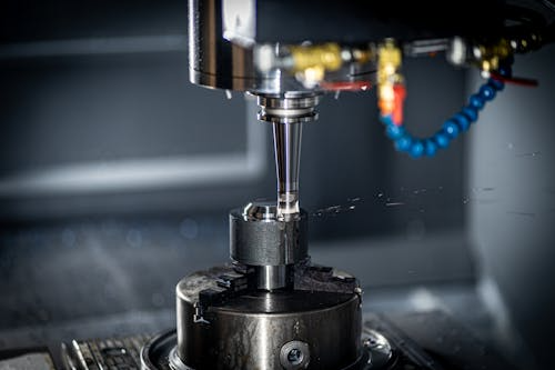
Conventional milling may produce more visible tool marks because the cutting edge rubs before cutting. It can also push chips ahead of the cutter, increasing chip recutting and surface damage.
| Milling Factor | Climb Milling | Conventional Milling |
| Chip thickness | Thick to thin | Thin to thick |
| Rubbing tendency | Lower when stable | Higher at entry |
| Surface finish | Often better on rigid CNC machines | Often rougher if rubbing occurs |
| Backlash risk | Higher on loose machines | Lower on backlash-prone machines |
| Tool loading | Can pull into cut | More resisting force |
| Best use | Stable finishing and controlled CNC setups | Roughing, manual machines, unstable stock |
When Machine Rigidity Determines The Correct Milling Strategy
Machine rigidity determines the correct milling strategy because cutting force must be controlled by the machine structure, axis drive, spindle, toolholder, and fixture. A method that works well on a rigid CNC machining center may be risky on a worn or backlash-prone machine.
Climb milling depends heavily on control. If the table, axis, or tool can move unexpectedly, the cutter may grab the part. Conventional milling is often safer where backlash or compliance exists.
Why Backlash Can Turn Climb Milling Into A Quality Problem
Backlash can turn climb milling into a quality problem because the climb milling force can pull the table or workpiece in the feed direction. If the machine has mechanical play, the cutter may advance faster than intended.
This creates tool grabbing, poor surface finish, dimensional error, and possible part damage. Manual milling machines are especially vulnerable because backlash is not controlled by CNC servo feedback in the same way.
University shop safety references often warn against climb milling on manual machines unless conditions are controlled. The issue is not that climb milling is poor. The issue is that climb milling requires machine control. [4]
How Modern CNC Machines Changed The Climb Vs Conventional Decision
Modern CNC machines changed the climb vs conventional decision because ball screws, servo control, spindle rigidity, and closed-loop positioning reduce backlash risk. This makes climb milling practical for many finishing and production operations. [3]
CNC machines can maintain smoother feed, controlled engagement, and repeatable toolpaths. This allows programmers to use climb milling for improved finish and tool life when the setup is stable.
Still, machine age and condition matter. A worn spindle, loose axis, weak workholding, or excessive tool stickout can make climb milling unstable even on CNC equipment.
Which Machine Conditions Should Be Evaluated Before Selecting A Toolpath Direction?
Machine conditions that should be evaluated include backlash, spindle condition, axis accuracy, machine wear, toolholder rigidity, and machine vibration history. Milling direction should not be selected before the machine condition is understood.
| Machine Condition | Why It Matters | Milling Direction Risk |
| Axis backlash | Allows uncontrolled movement | Climb milling pull-in |
| Worn spindle | Increases vibration | Poor finish and tool wear |
| Weak toolholder | Reduces rigidity | Deflection and chatter |
| Poor axis accuracy | Shifts the toolpath position | Dimensional error |
| Machine vibration | Affects surface finish | Chatter marks |
| Old/manual machine | Less feed control | Climb milling safety risk |
How Workholding Strength Changes Milling Performance
Workholding strength changes milling performance because the fixture must resist cutting forces from the chosen direction. A weak fixture can allow part movement, vibration, lift, or distortion.
A toolpath that is correct in CAM can fail if the part is not clamped along the correct load path. The fixture must support the workpiece against the direction of the cutter force.
Why Weak Fixturing Can Cause Part Movement During Climb Milling
Weak fixturing can cause part movement during climb milling because the cutter may pull the workpiece into the cut. If the clamp direction, support surface, or locating system is weak, the part can shift during machining.
This is common in thin plates, small parts, tall parts, castings, and components with limited clamping area. Movement may be small enough to avoid obvious damage but large enough to fail tolerance.
Corrective actions include stronger clamping, improved support, reduced radial engagement, lower cutting force, and changing the toolpath direction.
When Conventional Milling Provides Better Process Stability
Conventional milling can provide better process stability when rough stock, limited support, scale, casting skin, or fixture uncertainty exists. It may reduce the tendency of the cutter to pull into the part.
This can be useful during roughing, especially before the part has stable reference surfaces. After roughing and fixturing are improved, climb milling may be used for finishing passes.
The strongest process often uses both methods: conventional milling, where control is needed during roughing, and climb milling, where surface quality is needed during finishing.
How Fixture Design Influences Cutting-Force Control
Fixture design influences cutting-force control by determining how the part resists cutter load. Clamp orientation, support points, rest pads, locating pins, and vise pressure all affect stability.
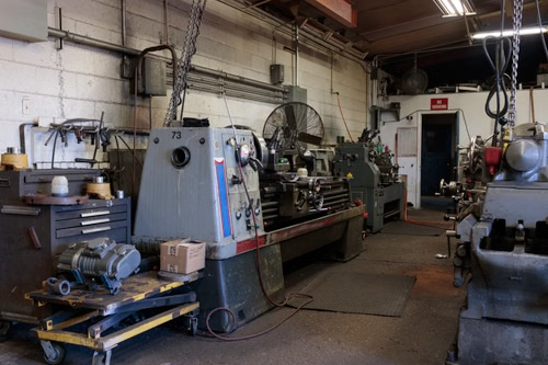
A fixture should support the part near the cutting zone when possible. Unsupported areas may vibrate, bend, or shift. This is especially important for thin walls, pockets, and long parts.
| Fixture Issue | Failure Mode | Correction |
| Clamp load not aligned with force | Part shift | Reorient clamps or toolpath |
| Unsupported thin feature | Chatter or deflection | Add support for a machine in stages |
| Weak locating surface | Datum movement | Improve locating geometry |
| Excessive vise pressure | Part distortion | Use balanced clamping |
| Poor access | Long tool requirement | Redesign the fixture or operation sequence |
Why Thin Walls And Lightweight Features Respond Differently To Milling Direction
Thin walls and lightweight features respond differently to milling direction because cutting forces can bend unsupported material. The milling method changes whether the wall is pushed into support, pulled away from support, or excited into vibration.
This is a major issue in aerospace brackets, electronics housings, heat sinks, and lightweight aluminum components. A wall may pass CAD review but fail during machining due to the force direction.
How Cutting Forces Affect Thin-Wall Deflection
Cutting forces affect thin-wall deflection by pushing or pulling material during engagement. Thin walls have low stiffness, so they may flex away from the cutter and spring back afterward.
This creates wall thickness variation, poor straightness, taper, chatter marks, and surface finish problems. In severe cases, the part may pass in-process measurement while clamped but fail final inspection after unclamping.
Milling direction should be selected based on wall support. The goal is to load the wall in the direction that minimizes movement.
Which Milling Direction Better Supports Wall Stability?
The milling direction that better supports wall stability depends on tool engagement, wall geometry, and fixture support. There is no universal answer for every thin-wall part.
Climb milling may improve the finish if the wall is supported and the tool engagement is controlled. Conventional milling may be safer if climb forces would pull the wall or part into the cutter.
For critical thin walls, programmers often leave finish stock, rough both sides evenly, reduce radial engagement, use sharp tools, and finish with the direction that produces the least measured deflection.
Aerospace Example: Pocketed Aluminum Bracket With Tight Wall-Tolerance Requirements
Aerospace pocketed aluminum brackets often include thin ribs and weight-reduction pockets. These designs reduce mass but make machining direction more important.
If climb milling pulls a thin wall away from support, the wall thickness may fail. If conventional milling rubs and heats the wall, finish, and dimensional control may suffer. The correct process must control cutting force, roughing sequence, support, and inspection.
For lightweight aerospace parts, milling direction is not a programming preference. It is part of the dimensional-control strategy.
How Material Properties Influence The Climb Vs Conventional Decision
Material properties influence the climb vs conventional decision because aluminum, stainless steel, titanium, and cast materials behave differently under cutting forces. Chip formation, heat generation, tool wear, and surface tearing all depend on material response.
A strategy that produces excellent results in 6061 aluminum may not behave the same in titanium or cast iron.
Why Aluminum, Stainless Steel, Titanium, And Cast Materials Behave Differently
Aluminum is ductile and can form built-up edge when rubbing and heat are not controlled. Climb milling often helps produce cleaner finishes in aluminum when the setup is rigid.
Stainless steel generates more heat and can work harden if cutting conditions are poor. Titanium retains heat near the cutting zone and requires careful tool engagement. Cast materials may include hard outer layers, scale, or interrupted cutting conditions.
Material behavior should be reviewed before selecting milling direction, cutter geometry, feed per tooth, coolant, and engagement strategy.
When Built-Up Edge And Material Smearing Become Major Risks
Built-up edge and material smearing become major risks when ductile material rubs instead of cutting cleanly. Conventional milling can increase this risk at entry because chip thickness starts near zero.
This can create surface tearing, poor finish, tool edge buildup, and dimensional variation. Aluminum parts with cosmetic or sealing surfaces are especially sensitive.
Climb milling may reduce rubbing on stable machines, but the tool must remain sharp, and chip load must be high enough to cut instead of polish.
Why Hard Surface Layers And Scale Sometimes Favor Conventional Milling
Hard surface layers and scale sometimes favor conventional milling during roughing because climb milling can impact the cutting edge immediately at maximum chip thickness. This can be hard on tools when cutting cast skin, oxidized stock, or irregular forged material.
Conventional milling may allow a more gradual entry into the cut. After the rough surface is removed, climb milling may be used for finishing.
This approach is common when the stock condition is uncertain or when the first operation must create stable reference surfaces.
How Tool Wear And Cutter Life Change With Milling Direction
Tool wear and cutter life change with milling direction because chip thickness, rubbing, heat, and edge loading are different. Metal cutting theory links tool wear to cutting temperature, edge contact, load, and material behavior.
A worn cutter also changes how climb and conventional milling perform. A toolpath that works with a sharp cutter may produce poor results after edge wear develops.
Which Cutting Strategy Reduces Rubbing And Edge Breakdown?
Climb milling often reduces rubbing and edge breakdown on rigid CNC machines because the cutter starts with a real chip and exits with a thinner chip. This can reduce heat at the entry and improve the surface finish.
Conventional milling can increase rubbing at the beginning of the cut. If the chip load is too low, the cutter may slide before cutting, increasing heat and wear.
However, unstable climb milling can chip tools if engagement is too aggressive. Tool life depends on the full system, not milling direction alone.
How Worn Tools Behave Differently In Climb And Conventional Milling
Worn tools behave differently because cutting edges become less sharp and require more force. Conventional milling may rub more heavily with a dull edge. Climb milling may become more unstable if the tool pulls under a higher cutting load. [5]
A worn tool can create chatter, burrs, poor finish, and dimensional drift. Inspection may show surface defects before dimensional failure appears.
Tool wear records should be reviewed alongside surface roughness data and dimensional reports. This helps connect process changes to part quality.
Why Deep Pockets And Long Tools Create Additional Milling Risks
Deep pockets and long tools create additional milling risks because tool stickout increases deflection. Milling direction changes how that deflection appears on the wall, floor, and corner surfaces. [7]
A long tool can bend under cutting force, causing taper, chatter, poor finish, and tolerance failure. This is common in molds, housings, pockets, enclosures, and valve bodies.
How Tool Deflection Changes During Deep-Pocket Machining
Tool deflection increases as tool stickout increases. A long cutter behaves less rigidly than a short cutter, especially under high radial engagement.
In climb milling, cutter pull can affect wall accuracy if the tool and part are not stable. In conventional milling, rubbing and heat can worsen the finish and tool wear.
Deep-pocket machining should use reduced radial engagement, staged roughing, adequate chip evacuation, and finish passes that minimize force.
Which Milling Strategy Better Controls Long-Reach Cutting Operations?
The best milling strategy for long-reach cutting depends on tool stiffness, wall support, engagement, and surface requirements. Climb milling is often preferred for the final finish when rigidity is adequate. Conventional milling may be useful during roughing or when the pull-in risk is high.
Programmers should avoid applying one method to every wall of a deep pocket. Opposite walls may respond differently because the cutting force direction changes.
How Inspection Results Reveal Milling-Process Problems
Inspection results reveal milling-process problems because defects often show up as surface marks, burr direction, taper, wall variation, chatter, or inconsistent roughness. Dimensional inspection alone may not explain why the part is failing.
Quality engineers should connect inspection findings to toolpath direction, cutter condition, workholding, and material behavior.
Which Surface Defects Point To Incorrect Milling Direction?
Surface defects that may point to incorrect milling direction include chatter marks, tearing, feed marks, burrs on critical edges, wall taper, and inconsistent finish.
Chatter may indicate weak support, excessive tool stickout, or unstable cutter loading. The Burr direction may show where the cutter exits the material. Surface tearing may indicate rubbing, built-up edge, or poor chip evacuation.
These findings help programmers adjust milling direction, engagement, cutting speed, feed, and tool selection.
Why Dimensional Accuracy Alone Does Not Tell The Full Story
Dimensional accuracy alone does not tell the full story because a part may meet size but fail surface integrity, edge quality, sealing performance, or cosmetic requirements.
A sealing face with chatter may leak even if its dimensions are acceptable. A medical device component with burrs may fail a safety review. An electronics enclosure with visible tearing may fail cosmetic inspection.
Inspection should include surface roughness, burr control, wall quality, and functional surface review where required.
Manufacturing Data To Review Before Process Approval
Manufacturing data should be reviewed before process approval because milling direction affects several measurable outcomes. Surface roughness reports, tool wear records, chatter history, CMM data, and burr inspection all help validate the process.
| Manufacturing Data | What It Shows | Process Decision Supported |
| Surface roughness report | Finish quality | Finishing direction selection |
| Tool wear record | Edge breakdown | Toolpath and cutter adjustment |
| Chatter analysis | Stability issue | Workholding or engagement change |
| Wall thickness data | Deflection risk | Thin-wall strategy |
| Burr inspection | Edge breakout behavior | Direction and deburring plan |
| Dimensional inspection | Accuracy trend | Process approval |
Industry Examples Where Milling Direction Determines Production Success
Milling direction determines production success in automotive, aerospace, medical, electronics, and industrial manufacturing because each sector has different risks. Some prioritize cycle time. Others prioritize surface integrity, burr control, thin-wall stability, or tool life.
Automotive Components: Balancing Surface Quality And Production Speed
Automotive components such as transmission housings, EV battery components, and structural brackets require repeatable machining at controlled cost. Milling direction affects tool wear, surface finish, and production consistency.
Climb milling may be used for final faces and profiles on rigid production equipment. Conventional milling may be used during roughing when stock condition or fixturing risk requires safer engagement.
Aerospace Components: Controlling Thin-Wall Stability And Surface Integrity
Aerospace parts such as lightweight brackets, structural fittings, and pocketed aluminum components often include thin walls and high material-removal ratios. Milling direction affects wall deflection and surface integrity.
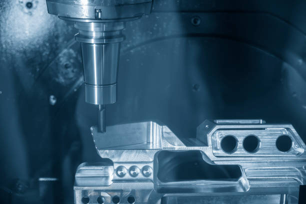
Aerospace machining should not select climb milling only because it improves finish. The part’s stiffness, support, tool engagement, and inspection requirements must control the decision.
Medical Device Components: Achieving Burr Control And Precision Surfaces
Medical device components such as instrument handles, surgical tooling, diagnostic housings, and precision fixtures require burr control and clean surfaces. Milling direction can change burr location and surface tearing.
For medical parts, the best process is the one that creates reliable surfaces and accessible burr removal. A visually clean surface is not enough if edges remain unsafe or difficult to inspect.
Electronics Components: Managing Heat Sinks, Housings, And Thin Features
Electronics parts such as CNC enclosures, RF housings, heat sinks, and cooling fins often include thin features and cosmetic surfaces. Milling direction affects tool marks, thin-fin deflection, and final appearance.
Climb milling is often useful for finishing visible aluminum surfaces, but heat-sink fins and thin walls need careful support. The strategy must protect flatness, surface quality, and assembly fit.
Industrial Equipment Components: Reducing Tool Wear While Maintaining Accuracy
Industrial parts such as valve blocks, tooling plates, robotic components, manifolds, and brackets often require durable surfaces and accurate hole relationships. Milling direction affects tool life and dimensional consistency.
Valve blocks may need stable roughing and accurate finishing. Tooling plates may need clean faces and flatness. Robotic grippers may include thin sections where cutting force direction affects accuracy.
Which Engineering Records Should Be Reviewed Before Selecting Milling Direction?
Engineering records should be reviewed before selecting milling direction because the toolpath direction must support the part’s function, material, tolerance, and inspection needs. The decision should be made before final programming, not corrected after scrap appears.
Engineering Records To Review
| Engineering Record | Why It Matters |
| CAD model | Shows walls, pockets, access, and cutter direction |
| Tolerance drawing | Identifies critical surfaces and dimensions |
| Material specification | Predicts heat, chip behavior, and built-up edge risk |
| Surface-finish requirements | Determines finishing strategy |
| Fixture plan | Confirms force resistance and support |
| Inspection plan | Shows how process success will be verified |
Manufacturing Data To Review
| Manufacturing Data | Why It Matters |
| Machine capability report | Confirms rigidity and axis condition |
| Backlash measurement | Identifies climb milling pull-in risk |
| Tool wear history | Shows edge life and failure pattern |
| Workholding validation | Confirms fixture stability |
| Surface roughness data | Confirms finish quality |
| Inspection reports | Shows dimensional and surface trends |
Decision Framework: How To Choose Between Climb And Conventional Milling
The choice between climb and conventional milling should be based on force control, machine rigidity, workholding strength, material condition, surface finish, and inspection results. The best choice is not universal. [8]
Use Climb Milling When:
Use climb milling when machine rigidity is high, workholding is stable, surface finish is critical, chip evacuation is important, and backlash risk is low.
It is commonly used for finishing passes, aluminum profiles, clean cosmetic surfaces, and controlled CNC production. It works best when tool engagement is stable, and the part cannot move under cutter pull.
Use Conventional Milling When:
Use conventional milling when backlash risk exists, rough stock surfaces are present, setup stability is limited, or process control favors safer cutter engagement.
It may be useful for roughing cast surfaces, oxidized stock, unstable workpieces, or manual machines. It can also help when climb milling creates pull-in or chatter problems.
Questions Engineers Should Answer Before Finalizing Toolpaths
Before finalizing toolpaths, engineers should answer these questions:
| Question | Why It Matters |
| How rigid is the machine? | Determines climb milling stability |
| How stable is the fixture? | Prevents part movement |
| What is the material condition? | Controls rubbing, scale, heat, and tool wear |
| What finish is required? | Determines finishing direction |
| Are thin walls present? | Controls deflection strategy |
| How will the feature be inspected? | Validates process choice |
| Is the tool stickout long? | Increases deflection risk |
Frequently Asked Questions
Is climb milling better than conventional milling?
Climb milling is often better on rigid CNC machines when surface finish and chip evacuation matter. It is not always better if backlash, weak fixturing, or unstable stock creates pull-in risk.
When should conventional milling be used?
Conventional milling should be used when backlash risk exists, rough stock surfaces are present, setup stability is limited, or climb milling causes part movement or chatter.
Why does climb milling improve surface finish?
Climb milling often improves surface finish because it reduces rubbing and starts with a real chip instead of sliding into the cut. This works best on stable CNC setups.
Why is climb milling risky on manual machines?
Climb milling is risky on manual machines because backlash can allow the cutter to pull the table or workpiece into the cut, causing tool grab, part damage, or unsafe movement.
Does material affect climb vs conventional milling?
Yes. Aluminum, stainless steel, titanium, and cast materials respond differently to heat, chip formation, built-up edge, scale, and tool wear. Milling direction should match material behavior.
Which method is better for thin walls?
The better method depends on wall support and force direction. The correct strategy is the one that minimizes wall deflection, chatter, and surface damage.
Can both milling methods be used on one part?
Yes. Conventional milling may be used for roughing unstable stock, while climb milling may be used for final finishing on stable surfaces.
How do inspection results help choose milling direction?
Inspection results show chatter, burrs, surface roughness, wall taper, tool marks, and dimensional drift. These results help engineers adjust toolpath direction and cutting conditions.
The Best Milling Strategy Is Determined By Force Control, Not By Habit
The best milling strategy is determined by force control, not habit. Climb milling and conventional milling are both useful when applied to the right machine, material, setup, and feature.
Climb milling is often preferred on rigid CNC machines because it can improve surface finish and reduce rubbing. Conventional milling remains useful when backlash, rough stock, limited support, or pull-in risk must be controlled.
Surface quality, tool life, dimensional accuracy, burr control, and inspection performance all depend on proper force management. For BaiChuan Precision Manufacturing, the correct strategy is the one that reduces manufacturing and quality risk for the specific part, not the one chosen by default.
References
- Stephenson, D. A., & Agapiou, J. S. Metal Cutting Theory and Practice. CRC Press, 2016.
https://www.routledge.com/Metal-Cutting-Theory-and-Practice/Stephenson-Agapiou/p/book/9781466587540 - Kalpakjian, S., & Schmid, S. R. Manufacturing Engineering and Technology. Pearson.
https://www.pearson.com/en-us/subject-catalog/p/manufacturing-engineering-and-technology/P200000003224 - Autodesk / TITANS of CNC Academy. Fundamentals of CNC Machining.
https://academy.titansofcnc.com/files/Fundamentals_of_CNC_Machining.pdf - University of California Riverside. For Manual Milling Machines. Mechanical Engineering SOP Manual.
https://me.ucr.edu/sites/default/files/2019-05/UCR-ME-SOP-Manual%20Milling%20Machines-v5.pdf - Reddy, D. R. G. S., & Narayan, A. Study of Worn Tool Machining Process in Climb and Conventional Milling.
https://publications.anveshanaindia.com/wp-content/uploads/2021/03/STUDY-OF-WORN-TOOL-MACHINING-PROCESS-IN-CLIMB-AND-CONVENTIONAL-MILLING-.pdf - Zubir, B. Comparative Analysis of Up and Down Milling on Surface Finish. Journal of Tribology, 2025.
https://jurnaltribologi.mytribos.org/v47/JTRIB-47-154-170.pdf - Metcut Research Associates. Machining Data Handbook.
https://archive.org/details/MachiningDataHandbook3rdEditionVol1 - Fictiv Engineering. Climb vs Conventional Milling: What Are The Differences?
https://www.fictiv.com/articles/climb-vs-conventional-milling-what-are-the-differences