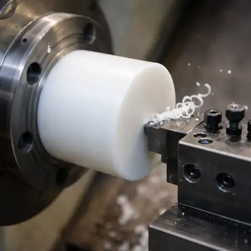
PE plastic deformation is a real problem. One wrong cut, and your part warps, twists, or shrinks out of tolerance. We have seen it happen more times than we can count.
Controlling PE deformation in CNC machining comes down to five core areas: understanding why deformation happens, reducing internal stress before cutting, managing heat during cutting, using the right fixturing, and controlling your feed rate. Get these five right, and your PE parts will hold their dimensions.
How to control PE plastic deformation in CNC machining
We work with PE materials regularly at our factory in Kunshan. Some of our customers come to us specifically because they have had deformation problems with other suppliers. What we have learned over the years is that PE behaves very differently from metal, and you cannot treat it the same way. The five methods below are what we use every day to keep our PE parts in tolerance.
Why Does PE Material Deform During CNC Machining?
Most machinists know PE deforms. But not many know exactly why it happens. Without understanding the root cause, you are just guessing at solutions.
PE deforms during CNC machining because it has a low thermal conductivity, a high thermal expansion coefficient, and significant internal stress from the manufacturing process. These three factors combine to make PE one of the most deformation-prone materials in the machine shop.
Why PE plastic deforms during CNC machining
To understand PE deformation, you need to look at the material at a deeper level. PE is a semi-crystalline polymer. This means it has both crystalline regions and amorphous regions inside its structure. These two regions respond to heat and cutting forces at different rates. When your cutting tool generates heat, the amorphous regions soften and relax faster than the crystalline regions. This uneven response creates stress inside the part, and that stress is what causes warping and dimensional shift.
The Three Root Causes of PE Deformation
| Cause | What Happens | Why It Matters |
|---|---|---|
| Low Thermal Conductivity | Heat stays in the cutting zone | Temperature builds up fast and softens the material |
| High Thermal Expansion | Material expands significantly under heat | Dimensions shift during and after cutting |
| Residual Internal Stress | Stress locked in from extrusion or molding | Released during machining, causing warping |
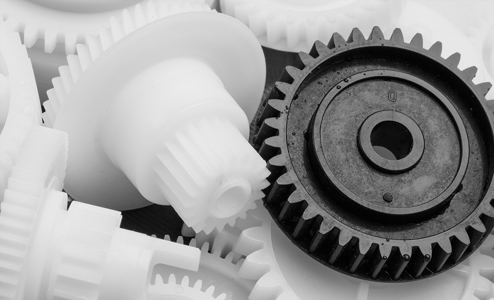
There is also a grade-specific factor. UHMWPE and HDPE behave very differently under the same cutting conditions. UHMWPE has a much higher molecular weight, which means it is more prone to smearing and gumming up your tool. HDPE is more forgiving but still requires careful heat management. Knowing your specific PE grade before you start planning your machining strategy is not optional. It is the first step.
What Are the Main Causes of Plastic Part Warping in Custom Machining?
You deliver a part that looks perfect. Your customer calls two days later and says it is warped. This happens. And it is frustrating for everyone involved.
Plastic part warping in custom machining is most often caused by uneven stress release, asymmetric material removal, and improper clamping. These three causes work alone or together to pull your part out of shape, sometimes hours or days after it leaves your machine.
Main causes of plastic part warping in CNC machining
Warping is not just a machining problem. It starts before you make your first cut. PE stock material carries internal stress from the extrusion or molding process used to make it. This stress is frozen in place as long as the material stays intact. The moment you start removing material, you break the balance of forces inside the part. Stress that was locked in now has room to move, and it does.
How Each Warping Cause Works
| Cause | Mechanism | Common Scenario |
|---|---|---|
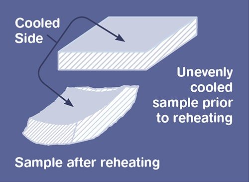
| Uneven Stress Release | Material relaxes at different rates across the part | One side of a flat plate curves up after facing |
| Asymmetric Material Removal | More material removed from one side creates force imbalance | Deep pockets machined only on one face |
| Improper Clamping | Excessive or uneven clamp force deforms part during machining | Thin walls crushed by standard vise jaws |
| Thermal Gradient | Uneven heat distribution causes uneven expansion | One end of a long part runs hotter than the other |
The most dangerous scenario is asymmetric material removal. When you machine a large pocket on one side of a PE plate, you remove the material that was balancing the internal stress on that side. The other side still has its original stress. The part bends toward the side where material was removed. The fix is to machine both sides in stages, alternating cuts to keep the stress balanced throughout the process. This adds time, but it is the correct way to handle this type of part.
How Can Internal Stress Be Reduced Before Machining PE Components?
You could be using the best tools, the right speeds, and perfect fixtures. But if your raw material is full of internal stress, your parts will still move after machining.
Internal stress in PE components can be significantly reduced before machining by using a two-stage annealing process. The first stage targets surface stress at around 80°C, and the second stage addresses deep internal stress relaxation at around 120°C.
How to reduce internal stress in PE before CNC machining
Annealing is the most effective pre-machining treatment for PE stock. The principle is simple. You heat the material to a controlled temperature, hold it there long enough for the stress to relax, and then cool it slowly. Fast cooling re-introduces stress, so the cooling rate matters as much as the heating temperature.
Two-Stage PE Annealing Protocol
| Stage | Temperature | Purpose | Hold Time |
|---|---|---|---|
| Stage 1 - Surface Relief | 80°C | Relax surface-level residual stress | 1 hour per 10mm of thickness |
| Stage 2 - Deep Relaxation | 120°C | Relax stress in the core of the material | 2 hours per 10mm of thickness |
| Cooling | Room temperature | Prevent re-introduction of thermal stress | Slow air cool, no quenching |
Beyond annealing, we also recommend a 24 to 48 hour rest period between roughing and finishing operations. Roughing releases a large amount of stress at once. The part needs time to stabilize before you machine the final dimensions. If you go straight from roughing to finishing without this rest period, the part will continue to move after the finishing operation. We have seen dimensional shifts of 0.1mm to 0.3mm occur in the hours after roughing. For parts with tight tolerances, that shift will put you out of spec before you even reach the inspection stage.
What Cooling Strategies Prevent Thermal Deformation in PE Plastics?
Heat is your biggest enemy when machining PE. Too much heat softens the material, changes its dimensions, and causes permanent deformation. Getting cooling right is not optional.
The best cooling strategies for PE plastics include minimum quantity lubrication (MQL) for HDPE grades and cryogenic cooling for UHMWPE grades. The goal is to remove heat from the cutting zone without flooding the part with liquid that causes its own dimensional problems.
Cooling strategies to prevent thermal deformation in PE plastics
Different PE grades respond to different cooling methods. This is one of the areas where you cannot use a one-size-fits-all approach. HDPE has a lower molecular weight and tolerates MQL well. A small, directed stream of mist keeps the tool cool and carries chips away from the cutting zone. UHMWPE is a different story. Its very high molecular weight means it smears rather than cuts cleanly when it gets warm. For UHMWPE, cryogenic cooling with liquid nitrogen or carbon dioxide brings the cutting zone temperature down low enough to keep the material brittle and chip-forming rather than soft and smearing.
PE Grade vs. Recommended Cooling Strategy
| PE Grade | Recommended Cooling | Why |
|---|---|---|
| HDPE | Minimum Quantity Lubrication (MQL) | Tolerates moderate temperatures, MQL keeps tool clean |
| UHMWPE | Cryogenic Cooling (LN2 or CO2) | High molecular weight causes smearing when warm |
| LDPE | Air Blast with MQL | Soft material, excessive liquid can cause dimensional issues |
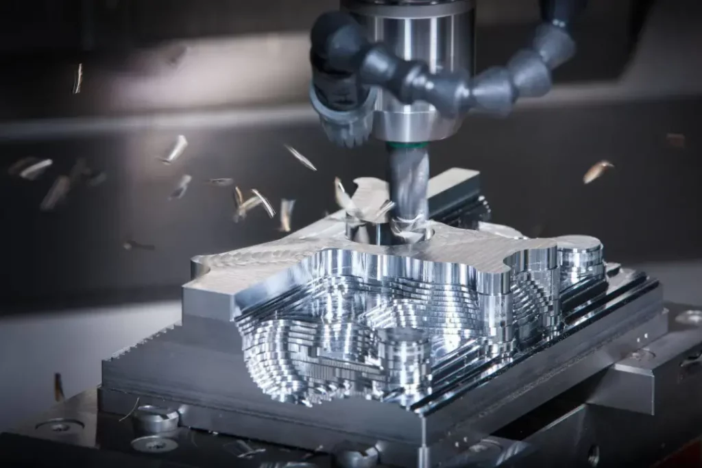
An intermittent cutting strategy works alongside your cooling method. Instead of continuous cuts, you pause the tool periodically to allow heat to dissipate. This approach reduces cumulative thermal exposure in the cutting zone significantly. For long facing operations on large PE plates, we use a pass-and-pause method where we stop the spindle every few minutes and let the part return to near room temperature before continuing. It adds time to the job, but it is far cheaper than scrapping a warped part.
Which Fixturing Techniques Minimize PE Part Distortion?
A part that is held incorrectly during machining will be wrong after machining. The way you clamp PE is completely different from the way you clamp aluminum or steel.
The fixturing techniques that minimize PE part distortion are vacuum fixtures, soft jaws, and distributed clamping. These methods spread clamping force over a large area and keep contact pressure below 1.5 MPa to prevent deformation at the clamping points.
Fixturing techniques to minimize PE part distortion in CNC machining
PE is soft and compliant. Standard metal vise jaws concentrate clamping force on a small area. That concentration of force is enough to locally deform the PE material, and that local deformation changes your part dimensions even after you release the clamp. The answer is to use fixtures that have contact surfaces three to five times larger than what you would use for equivalent metal parts.
Fixturing Method Comparison for PE Parts
| Fixturing Method | Contact Area | Max Pressure | Best For |
|---|---|---|---|
| Standard Vise Jaws | Small | High - often exceeds 1.5 MPa | Metal parts, not PE |
| Soft Jaws (HDPE or Aluminum) | Medium | Controllable | Turned PE components |
| Vacuum Fixture | Large | Very low, distributed evenly | Flat PE plates and sheets |
| Dedicated Nest Fixture | Full profile contact | Very low | Complex shaped PE parts |
| Toggle Clamps with Pads | Medium | Controllable | Secondary operations |
Vacuum fixtures are our preferred solution for flat PE work. They hold the part across its entire bottom face with almost no point loading. The part sits flat and stays flat during machining. For turned components, we make soft jaws from HDPE or aluminum with a profile that matches the part diameter. This spreads the chuck force across a larger area and prevents jaw marks from appearing on the finished surface. The principle in both cases is the same: distribute the clamping force, keep the pressure low, and never let the fixture do damage that your cutting tool then has to correct.
How Does Feed Rate Impact PE Material Dimensional Stability?
Speed settings matter for surface finish. Feed rate matters for dimensional stability. Many machinists focus on spindle speed and forget that feed rate has its own direct effect on whether your PE part holds its dimensions.
Feed rate impacts PE dimensional stability because it controls chip thickness and heat generation simultaneously. A feed rate that is too low causes rubbing instead of cutting, which generates excessive heat. A feed rate that is too high causes deflection forces that push material out of position.
The relationship between feed rate and PE behavior is a balance. On the low side, when the feed rate is too low, your tool is not cutting efficiently. It is rubbing and ploughing through the material rather than shearing it cleanly. This rubbing generates frictional heat directly at the surface of the part. That heat softens the PE locally, and the softened PE flows slightly under the cutting pressure. The result is a surface that looks machined but has residual stress and slight dimensional inaccuracy from the thermal softening.
Feed Rate Effects on PE Machining Outcomes
| Feed Rate Condition | Heat Generation | Cutting Force | Dimensional Risk |
|---|---|---|---|
| Too Low (Rubbing) | High - friction-dominated | Low | Thermal softening, surface smearing |
| Optimal Range | Low - clean chip formation | Moderate and consistent | Stable dimensions, predictable behavior |
| Too High (Overloading) | Moderate | High | Part deflection, fixture slippage |
Tool geometry works directly with feed rate. Positive rake angles in the range of 15 to 20 degrees are the right choice for PE machining. A positive rake angle reduces the cutting force needed to shear the material. Lower cutting force means less heat and less deflection. Diamond-like carbon (DLC) coatings on your cutting tools reduce friction further and extend tool life, which keeps your cutting geometry consistent across the full production run. A worn tool with degraded geometry will shift your optimal feed rate range and produce inconsistent results even if all your other parameters stay the same.
What Quality Control Methods Ensure PE Parts Meet Tolerance Requirements?
Your part looked good when it left the machine. It measured within tolerance when your operator checked it. Then your customer measures it three days later and says it is out of spec. This is a PE-specific quality control problem.
Quality control for PE parts must account for post-machining dimensional evolution. PE continues to change dimensions for 72 to 120 hours after machining as residual stresses relax. Effective QC methods include delayed final inspection, proactive dimensional compensation, and real-time thermal monitoring during machining.
The 72 to 120-hour dimensional evolution window is the part of PE quality control that catches most people off guard. The part does not instantly reach its final dimensions when the machine stops. Internal stress that was disturbed during machining continues to relax and redistribute for days afterward. The part moves. Sometimes this movement is small enough to ignore. For parts with tight tolerances, like aerospace-grade components requiring ±0.025mm, this movement is significant.
PE Part QC Protocol by Application
| Application | Tolerance Requirement | QC Method | Inspection Timing |
|---|---|---|---|
| General Industrial | ±0.1mm or looser | Standard CMM or manual measurement | 24 hours post-machining |
| Automotive Components | ±0.05mm | CMM with temperature-controlled room | 48 hours post-machining |
| Medical / Semiconductor | ±0.025mm or tighter | CMM + surface profilometer + thermal imaging | 72-120 hours post-machining |
| Aerospace | ±0.025mm or tighter | Full inspection protocol with documented thermal history | 120 hours post-machining |
The proactive compensation approach is the practical solution for high-tolerance work. We intentionally machine critical features 0.1% to 0.3% oversize at the finishing stage. We then re-inspect after the 72 to 120-hour stabilization period and do a light final pass if needed to bring the part to exact specification. For medical and semiconductor customers, we also maintain documented thermal histories for each part. This documentation shows that the part never exceeded its critical thermal threshold during machining, which satisfies regulatory and quality system requirements for those industries. Surface finish requirements for these applications, typically Ra below 0.4 μm, require diamond turning as the final operation.
Conclusion
Controlling PE deformation in CNC machining requires managing stress, heat, fixturing, feed rate, and inspection together. Get all five right, and your PE parts will consistently meet tolerance.