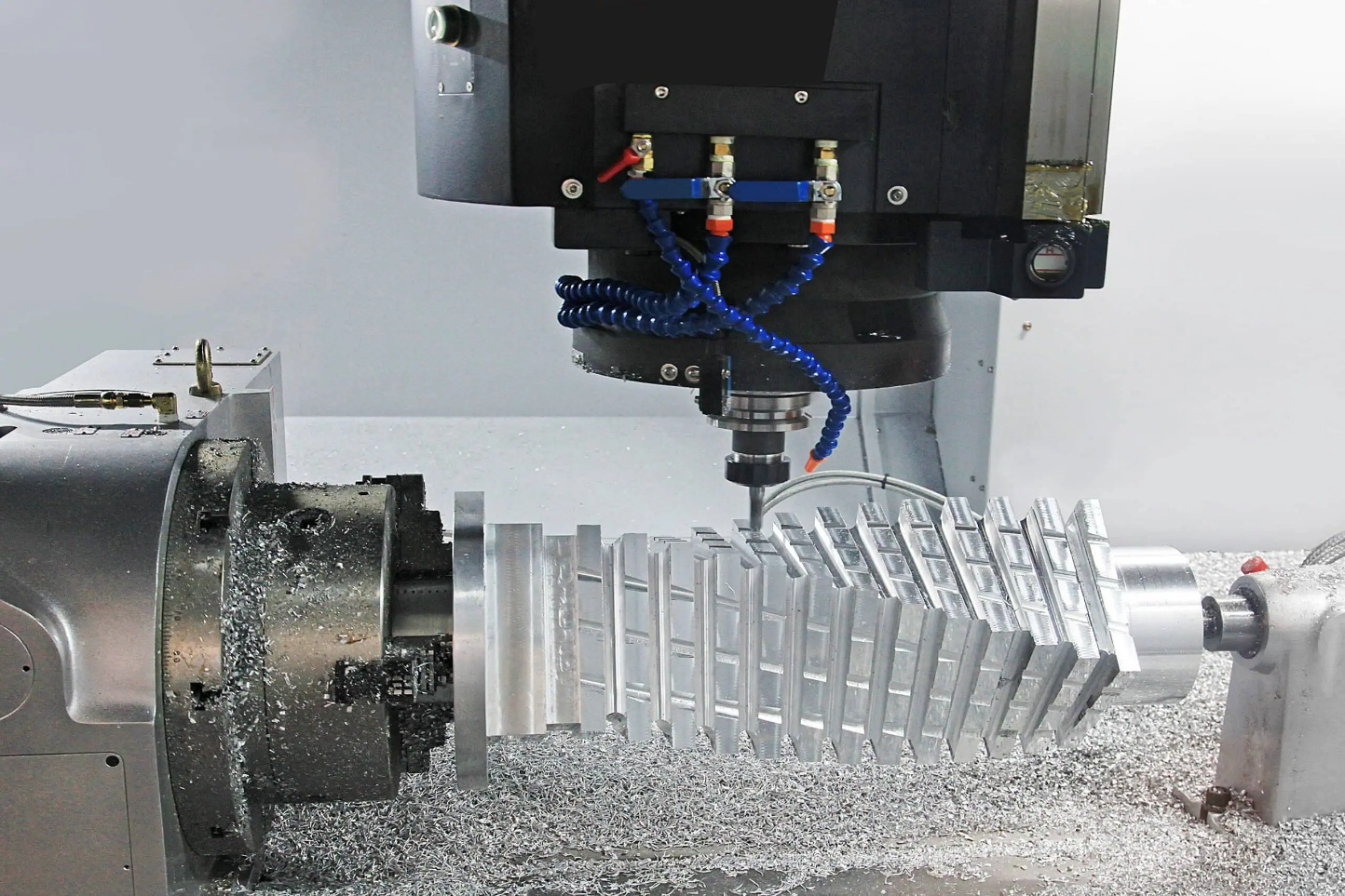
The surface finish on your CNC-machined parts can make or break your product. We've seen countless projects fail because someone picked the wrong abrasive method, resulting in parts that looked great but failed in the field.
Surface finishing determines how your machined components perform in real-world applications. The right abrasive technique enhances part functionality, appearance, and durability, while the wrong choice can compromise critical tolerances, create stress concentrations, or produce inconsistent results that impact product reliability.
I remember when a new automotive client came to us after rejecting parts from another supplier. Their components looked perfect visually, but premature failures were occurring because the supplier had used aggressive abrasives that created microscopic stress points. Let me walk you through what you need to know about abrasive finishing to avoid similar costly mistakes.
What Surface Roughness Can You Achieve with Different Grit Sizes?
When clients ask about surface finish, I often see confusion about what's actually possible. Many don't realize that the grit size they specify directly determines the final quality and performance of their parts.
Grit size refers to the number of abrasive particles per linear inch, with higher numbers indicating finer particles that produce smoother surfaces. For precision components, we typically use grit sizes ranging from 60 (rough) to 2000+ (mirror-like), with each increment providing measurably different roughness values measured in Ra (roughness average).
Understanding the relationship between grit size and achievable surface roughness is crucial for both our manufacturing team and our clients. The abrasive material world uses three main sizing systems that often cause confusion: mesh sizes, micron ratings, and grit numbers. Mesh sizes are determined by the number of openings per linear inch in a screen, while micron ratings measure the actual particle diameter. Grit numbers follow standardized scales set by organizations like FEPA (Federation of European Producers of Abrasives) or CAMI (Coated Abrasives Manufacturers Institute).
For practical application in our CNC shop, we've developed this reference table that converts between these measurement systems and shows the typical surface roughness achievable:
| Grit Number | Mesh Size | Particle Size (microns) | Achievable Ra (μin) | Typical Applications |
|---|---|---|---|---|
| 36-40 | 24-30 | 420-500 | 170-200 | Heavy stock removal, rough grinding |
| 60-80 | 40-60 | 180-250 | 90-120 | General machining, medium finishing |
| 120-150 | 100-120 | 75-125 | 40-60 | Fine finishing for industrial parts |
| 180-220 | 150-180 | 53-75 | 20-30 | Automotive components, tooling |
| 320-400 | 230-270 | 22-36 | 8-15 | Precision components, molds |
| 600-800 | 320-400 | 10-20 | 4-8 | Medical devices, optical parts |
| 1000+ | 500+ | <10 | 1-3 | Semiconductor parts, mirrors |
In our experience, most industrial applications require a finish in the 60-120 grit range, while aerospace and medical components often need 220-400 grit. For vacuum chamber components, which form a significant portion of our business, we typically recommend finishes in the 120-180 range to balance cleanliness requirements with production costs.
When Should You Choose Sandblasting vs. Bead Blasting for Aluminum Parts?
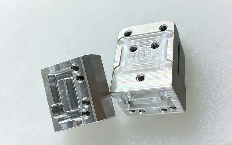
Last year, we had a client who ruined a batch of aluminum sailboat fittings by sandblasting them. The aggressive, angular media created stress points that eventually led to part failure in high-salt marine conditions.
The choice between sandblasting and bead blasting for aluminum depends primarily on your application requirements. Sandblasting uses angular media that cuts into the surface, creating a rougher finish with excellent paint adhesion but potentially weakening the part. Bead blasting uses spherical media that peens the surface, resulting in a more uniform, satin finish that maintains material integrity.
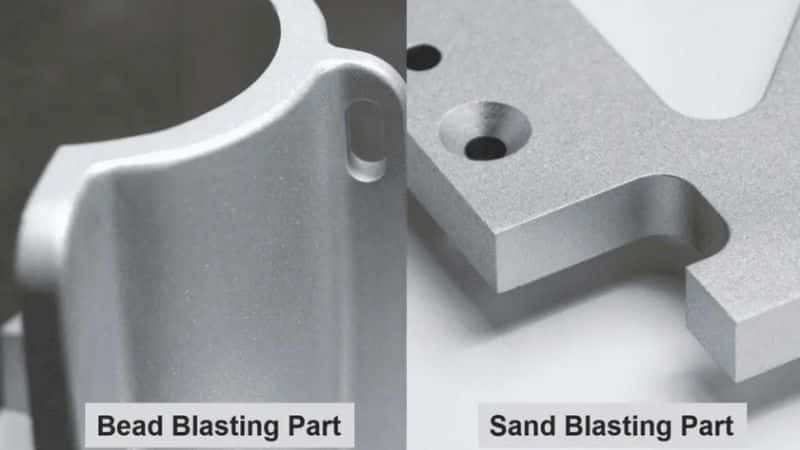
The decision between sandblasting and bead blasting for aluminum components requires careful consideration of both aesthetic and functional requirements. Sandblasting, which employs angular abrasive media like aluminum oxide or silicon carbide, creates a rougher surface profile with micro-cuts and valleys. This aggressive approach offers excellent paint and coating adhesion because it increases surface area and creates mechanical "anchors" for the coating to bond with. However, this same cutting action can introduce stress concentrations and potentially compromise the fatigue resistance of aluminum parts, especially in thin-walled sections.
Bead blasting, on the other hand, uses spherical glass or ceramic beads that impact the surface without cutting it. This peening action compresses the surface material, often increasing fatigue resistance while producing a uniform, satin-like appearance. For aluminum sailboat components and marine applications where corrosion and salt exposure are concerns, bead blasting typically provides superior results.
Our standard practice for aluminum parts at our factory includes:
| Parameter | Sandblasting | Bead Blasting |
|---|---|---|
| Typical Media | Aluminum oxide, silicon carbide | Glass beads, ceramic beads |
| Surface Finish | Rough, matte (Ra 125-250 μin) | Satin, uniform (Ra 32-125 μin) |
| Best For | Paint/coating preparation, Rust/scale removal | Decorative finishes, Stress relief, Cleaning without dimensional change |
| Pressure Range | 60-90 PSI | 30-60 PSI |
| Media Size | 60-120 grit | 70-270 mesh |
| Durability Impact | May reduce fatigue strength | May improve fatigue strength |
For critical aluminum components like our automotive and marine parts, we typically recommend bead blasting with glass media in the 100-170 mesh range at moderate pressure (40-50 PSI) to achieve the optimal balance between surface preparation and material integrity.
How Does Abrasive Selection Impact the Performance of Precision Components?
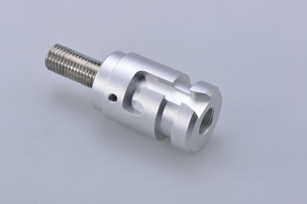
We once machined identical valve bodies for a client using two different abrasive finishing methods. The parts that underwent barrel finishing with ceramic media lasted 30% longer than those finished with a more aggressive silicon carbide process.
Abrasive selection directly affects a component's performance characteristics, including wear resistance, fatigue strength, friction properties, and dimensional stability. The wrong abrasive can introduce microscopic surface defects that become failure points under stress or cyclic loading.

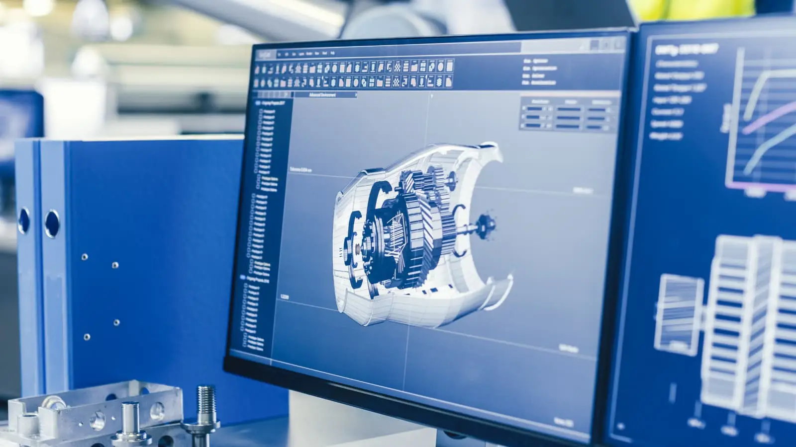
The selection of abrasive media represents one of the most crucial yet underappreciated aspects of precision component manufacturing. In our machining facility, we've observed firsthand how seemingly minor variations in abrasive characteristics can produce dramatically different outcomes in component performance. This goes far beyond aesthetics - the microscopic topology created by different abrasive media fundamentally alters how components interact with their environment.
Abrasive hardness, measured on the Mohs scale, must be appropriately matched to the workpiece material. Using excessively hard abrasives on softer metals can create deep scratches that act as stress concentrators, while abrasives that are too soft may fail to remove manufacturing artifacts like tool marks. Particle shape is equally important - angular particles cut more aggressively but can embed in softer materials, while spherical media creates a peened surface that often enhances fatigue resistance.
Our internal testing has shown that for precision components used in high-stress applications, controlled abrasive processes that create uniform, directional surface patterns typically outperform random finishing patterns. For rotating components like shafts and bearings, circumferential finishing patterns generally provide optimal performance, while for sliding components, longitudinal patterns reduce friction and improve wear characteristics.
The table below summarizes our findings on how different abrasive media affect key performance metrics:
| Abrasive Type | Material Removal Rate | Surface Finish (Ra) | Fatigue Strength Impact | Best Applications |
|---|---|---|---|---|
| Aluminum Oxide | High | 20-200 μin | Moderate reduction | General purpose, steel components |
| Silicon Carbide | Very High | 15-150 μin | Significant reduction | Hard materials, rapid stock removal |
| Ceramic Media | Medium | 25-125 μin | Slight improvement | Precision components, deburring |
| Glass Beads | Low | 10-80 μin | Moderate improvement | Cosmetic finishes, stress relief |
| Plastic Media | Very Low | 30-100 μin | Minimal impact | Delicate parts, thin sections |
| Walnut Shell | Extremely Low | 40-120 μin | No impact | Soft materials, historical restoration |
What Are the Industry Standards for Surface Finishing in Aerospace Applications?
A few months ago, an aerospace client rejected parts from another supplier because they didn't understand the AS9100 surface finish requirements. We helped them define proper specifications and now exclusively manufacture their critical components.
Aerospace surface finishing follows stringent standards that precisely define acceptable roughness values, pattern directionality, and surface integrity. These standards include AMS 2700 for surface finishing, AS9100 for quality systems, and specific OEM requirements from companies like Boeing and Airbus.
The aerospace industry maintains some of the most demanding surface finish requirements of any manufacturing sector, with standards that have evolved over decades to ensure component reliability in the most extreme operating conditions. In our experience producing aerospace components, we've found that understanding these standards isn't just about compliance—it's about developing manufacturing processes that consistently meet these exacting requirements.
Aerospace surface finishing specifications are typically defined through multiple, overlapping standards. The Aerospace Material Specification (AMS) series, particularly AMS 2700 "Passivation of Corrosion Resistant Steels" and AMS 2430 "Shot Peening, Automatic," establishes baseline requirements. These are further refined through AS9100 quality management systems that dictate documentation, traceability, and process control requirements specific to aerospace manufacturing.
Beyond these industry standards, each major aerospace OEM typically maintains its own proprietary specifications. For example, Boeing's BAC5730 for surface texture requirements or Airbus's AIMS03-02-011 for surface protection establishes additional criteria that suppliers must meet. These OEM standards often include specific callouts for surface roughness measured as Ra (Roughness Average), Rz (Mean Roughness Depth), and sometimes Rsk (Skewness) values.
For machined aerospace components, the typically accepted surface roughness ranges are:
| Component Type | Typical Ra Requirement | Common Abrasive Process | Inspection Method |
|---|---|---|---|
| Engine components | 8-32 μin (0.2-0.8 μm) | Fine grinding, honing, superfinishing | Profilometer, optical comparator |
| Structural components | 32-63 μin (0.8-1.6 μm) | Precision grinding, fine grit blasting | Profilometer, surface roughness comparator |
| Fastener holes | 32-125 μin (0.8-3.2 μm) | Reaming, honing | Bore scope with digital measurement |
| Aerodynamic surfaces | 16-32 μin (0.4-0.8 μm) | Precision grinding, fine-grit blasting | Optical measurement, laser scanning |
| Landing gear components | 16-63 μin (0.4-1.6 μm) | Shot peening, precision grinding | Almen intensity strips, profilometer |
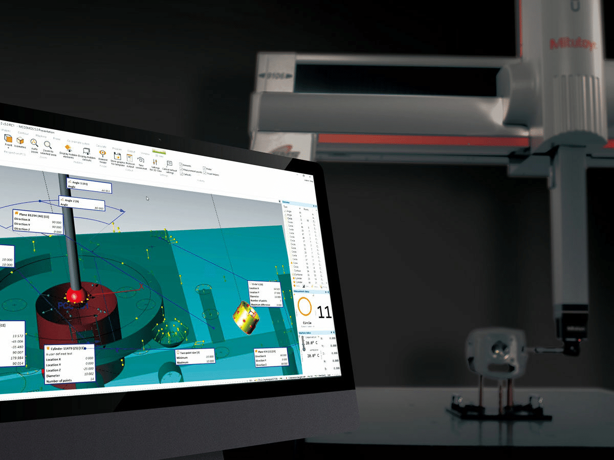
| Fuel system components | 8-16 μin (0.2-0.4 μm) | Lapping, superfinishing | Confocal microscopy, profilometer |
In our factory, we've invested in digital surface roughness measurement systems that allow us to validate and document surface finish compliance for every critical aerospace component. This approach not only ensures regulatory compliance but also provides valuable process data that helps us continuously improve our finishing operations.
Conclusion
Selecting the right abrasive finishing method directly impacts your CNC-machined parts' performance, appearance, and longevity. By understanding grit sizes, finishing techniques, and industry standards, you'll avoid costly mistakes and ensure your components perform as designed.