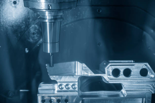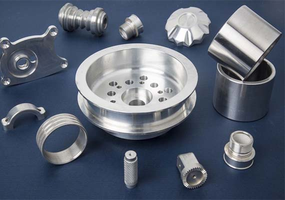

Quality control in CNC machining does not end when the last cutting pass is complete. A part can be machined with a perfectly programmed toolpath and still fail to meet its specification due to tool wear, fixture deflection, or thermal variation during the cutting process. Dimensional accuracy is the entire point of CNC machining, and verifying that accuracy before a part leaves the shop is what separates a reliable supplier from an unreliable one.
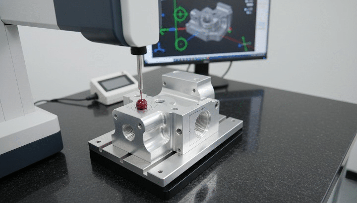
CMM Inspection Process for CNC Parts
Coordinate Measuring Machines, commonly known as CMMs, are the industry standard tool for verifying that machined parts meet their dimensional and geometric requirements. By measuring physical features against the original CAD model with sub-micron precision, CMM inspection gives manufacturers an objective, documented basis for confirming part quality before delivery.
What Is CMM Inspection?
CMM inspection is the process of using a coordinate measuring machine to verify that a manufactured part conforms to its design specifications. Understanding how the machine itself works is the foundation for understanding why this method of inspection has become indispensable in precision manufacturing.
What Is a Coordinate Measuring Machine (CMM)?
A coordinate measuring machine is a precision instrument that measures the physical geometry of an object by recording the position of points on its surface in three-dimensional space. A probe contacts the part at defined locations, and the machine records the X, Y, and Z coordinates of each contact point relative to a fixed reference frame. Software then compares these measured points against the nominal dimensions defined in the part's CAD model, calculating deviations for each inspected feature [1].
The key components of a CMM include:
- Probe: The sensing device that contacts or scans the part surface. Touch-trigger probes register a single point on contact, while scanning probes collect continuous data along a surface.
- Measuring table: A precision granite or ceramic surface that provides a stable, flat reference plane on which the part is positioned during inspection.
- Software: Controls probe movement, records measurement data, compares results against CAD nominal values, and generates inspection reports.
- X, Y, and Z axes: The three linear axes along which the probe moves to reach any point in the measuring volume, each fitted with high-resolution linear encoders that track position with micron-level accuracy.
Why CMM Inspection Is Important in CNC Machining
CMM inspection serves several functions that are difficult to replicate through manual measurement methods:
- Ensures parts match CAD drawings: Direct comparison against the digital model verifies that every measured feature falls within its specified tolerance, not just the features that are easy to check with hand tools.
- Verifies tolerances and geometric features: Complex geometric tolerances such as position, flatness, and perpendicularity are difficult or impossible to verify accurately with calipers or micrometers, but are measured routinely and objectively by a CMM.
- Reduces defects and rework: Identifying dimensional problems before parts are shipped or assembled prevents downstream failures that are far more costly to correct later in the production chain.
- Improves customer confidence: Documented inspection reports provide objective evidence of conformance, supporting quality agreements and regulatory requirements in industries such as aerospace and medical devices [2].
A CNC-machined aerospace bracket specified to a positional tolerance of ±0.01 mm on its mounting holes illustrates why CMM inspection is necessary rather than optional. At this tolerance level, manual measurement tools cannot reliably confirm conformance, and the geometric relationship between multiple holes, not just their individual diameters, must be verified. A CMM measures each hole's actual position relative to the part's datum features and confirms whether the bracket meets the positional tolerance before it is approved for assembly into the aircraft structure.
How CMM Inspection Works for CNC Parts
CMM inspection follows a structured sequence from part preparation through to final reporting. Each step contributes to the overall accuracy and reliability of the inspection result, and skipping or rushing any stage introduces the risk of measurement error.
Step 1: Preparing the CNC Part
- Cleaning the part: Chips, coolant residue, and cutting fluid must be removed from the part surface before measurement, as any contamination on a measured feature introduces error into the probe contact point.
- Stabilizing temperature: CMM measurements are highly sensitive to thermal expansion. Parts machined under coolant flow or in a warm shop environment are typically allowed to stabilize to the CMM room's controlled temperature, often 20°C, before measurement begins, particularly for tight-tolerance components [3].
- Positioning and fixturing: The part is placed on the measuring table and secured, either resting freely for simple geometries or held in a dedicated fixture for parts that require consistent orientation or have features that would otherwise be inaccessible to the probe.
Step 2: Loading CAD Data and Inspection Program
- Importing design specifications: The part's CAD model, including nominal dimensions and tolerance callouts, is imported into the CMM software, establishing the reference geometry against which measurements will be compared.
- Defining measurement points: An inspection program is created, either manually or through CAD-based programming, specifying which features will be measured, the sequence of probe movements, and the specific points or scan paths on each feature.
Step 3: Measuring the Part
- Probe contacts selected surfaces: The CMM executes the programmed routine, moving the probe to each defined location and registering contact points on the part surface.
- Data points collected automatically: For each feature, multiple points are typically collected to define its geometry accurately, such as several points around a bore circumference to calculate diameter and roundness.
- Comparison against design dimensions: The software calculates each feature's actual dimension or geometric characteristic from the collected points and compares it against the nominal value and tolerance band defined in the CAD data.
Step 4: Generating Inspection Reports
- Pass/fail results: Each measured feature is flagged as within tolerance or out of tolerance, providing an immediate summary of part conformance.
- Dimensional deviation analysis: Detailed reports show the actual measured value, the nominal value, and the deviation for every inspected feature, supporting root cause analysis when deviations are found.
- Documentation for quality records: Reports are archived as part of the manufacturing quality record, supporting traceability requirements and customer quality agreements.
Inspecting a CNC-machined aluminum housing with multiple holes, slots, and mounting surfaces demonstrates the value of a structured CMM routine. Rather than manually checking each feature with calipers and a height gauge, a single CMM program measures every hole diameter and position, slot width and location, and surface flatness in one automated sequence, producing a complete dimensional report in a fraction of the time manual inspection would require, with substantially greater accuracy on the geometric relationships between features.
Types of Measurements Performed During CMM Inspection
CMMs are capable of measuring a wide range of dimensional and geometric characteristics, many of which would be impractical or impossible to verify using conventional hand tools.
Linear Dimensions
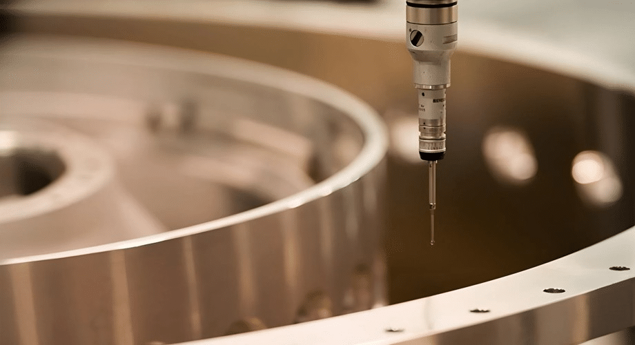
Basic linear measurements such as length, width, and height are verified by recording probe contact points at the relevant feature boundaries and calculating the distance between them. While these dimensions can sometimes be checked manually, CMM measurement provides greater accuracy and removes operator-dependent variation, particularly for features that are difficult to access with calipers.
Hole and Bore Inspection
Holes and bores require more than a simple diameter check to confirm full conformance:
- Diameter: Calculated from multiple points around the bore circumference, providing a more reliable result than a two-point caliper measurement, which can miss out-of-round conditions.
- Position: The actual center location of the hole is compared against its nominal position relative to part datums, verifying positional tolerance compliance.
- Roundness: Deviation from a perfect circle is calculated from the collected points, identifying issues such as tool deflection or chatter that a simple diameter check would not reveal [4].
Geometric Dimensioning and Tolerancing (GD&T)
CMMs are uniquely suited to verifying GD&T callouts that define the geometric relationships between features rather than simple size:
- Flatness: Measures the deviation of a surface from a perfect plane, relevant for sealing surfaces and mounting faces.
- Parallelism: Verifies that two surfaces or features maintain a consistent relationship to one another within the specified tolerance.
- Perpendicularity: Confirms that a feature is oriented at a true right angle to a referenced datum, critical for shoulder faces and mounting interfaces.
- Position tolerance: Defines an allowable zone within which a feature's actual location may vary relative to specified datums, commonly applied to hole patterns and other located features.
Surface and Feature Analysis
Beyond basic dimensions and GD&T callouts, CMMs measure more complex feature characteristics, including angles between surfaces, slot width and location, and complex contours where the part geometry is compared point-by-point against a CAD surface model rather than against simple geometric primitives.
Example
Measuring the location and diameter of bolt holes on a CNC-machined automotive component shows these measurement types working together. The CMM verifies each hole's diameter to confirm it accepts the specified fastener, checks the position of each hole relative to the component's mounting datums to ensure correct alignment with the mating assembly, and may also verify the perpendicularity of the hole axis to the mounting surface to ensure the fastener seats correctly without inducing bending stress.
Types of CMMs Used in CNC Manufacturing
Different CMM architectures are suited to different part sizes, geometries, and inspection environments. Selecting the appropriate machine type depends on the parts being produced and the inspection workflow required.
Bridge CMM
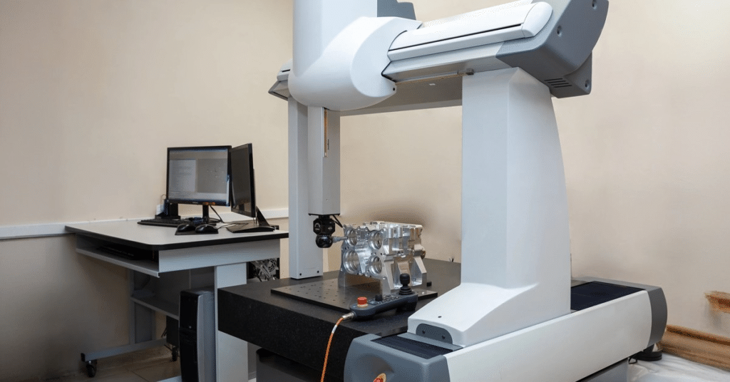
The bridge CMM is the most common configuration in precision manufacturing, featuring a moving bridge structure that spans the measuring table and carries the vertical Z-axis assembly. This design offers excellent rigidity and accuracy, making it the standard choice for precision-machined components across most industries [5].
Cantilever CMM
Cantilever CMMs support the measuring arm from one side only, leaving the front and sides of the measuring table open for easy part loading and access. This configuration is well-suited to smaller workpieces and applications where frequent part changes make easy access a priority, though the cantilevered structure offers somewhat less rigidity than a bridge design at larger sizes.
Gantry CMM
Gantry CMMs are large-scale machines supported on floor-mounted columns, designed to measure large CNC-machined parts such as automotive body structures, large castings, or aerospace structural components that would not fit within the measuring volume of a standard bridge or cantilever machine.
Portable CMM and Articulated Arm Systems
Portable CMMs, including articulated arm measuring systems, allow inspection to be performed directly at the machine tool or on the shop floor rather than requiring the part to be transported to a dedicated metrology room. These systems offer flexibility for large or immovable parts and support in-process inspection, though typically with somewhat lower accuracy than a fixed bridge CMM in a controlled environment [6].
Example Applications
- Medical devices: Bridge CMMs verify the tight tolerances required on surgical instruments and implantable device components.
- Aerospace components: Both bridge and gantry CMMs inspect everything from small precision brackets to large structural assemblies.
- Automotive parts: Bridge CMMs are standard for engine and transmission components, while gantry systems handle body panels and large structural parts.
- Industrial machinery components: Cantilever and bridge CMMs verify gearbox housings, shafts, and mounting structures across general industrial manufacturing.
Benefits of CMM Inspection for CNC Parts
The adoption of CMM inspection across precision manufacturing reflects measurable advantages over manual inspection methods, both in terms of part quality and overall production efficiency.
Improved Accuracy and Consistency
CMM measurement eliminates the operator-dependent variation inherent in manual measurement with calipers, micrometers, and gauges. The same inspection program produces consistent results regardless of which operator runs it, removing a significant source of measurement uncertainty from the quality control process [7].
Faster Quality Control
Automated inspection routines measure dozens or hundreds of features in a single program execution, far faster than manually checking each dimension with hand tools. This speed advantage becomes particularly significant for parts with complex geometry or numerous critical features.
Reduced Scrap and Rework
Early detection of dimensional problems through CMM inspection, particularly when integrated into in-process or first-article inspection routines, allows manufacturers to identify and correct machining issues before an entire batch is produced out of tolerance, substantially reducing scrap rates and rework costs.
Better Process Optimization
CMM data collected across a production run reveals trends that point to underlying process issues, such as gradual dimensional drift indicating tool wear, or recurring deviations pointing to a fixture or programming error. This data supports continuous process improvement beyond simple pass/fail inspection.
Traceability and Documentation
Inspection reports generated by CMM software provide a documented quality record for every part or batch, supporting customer quality agreements, regulatory compliance, and audit requirements in regulated industries such as aerospace and medical device manufacturing.
Example
Using CMM reports to identify tool wear causing oversized holes during CNC production illustrates the process optimization benefit clearly. If a series of inspection reports shows hole diameters gradually trending toward the upper tolerance limit across sequential parts, this pattern points directly to insert wear in the boring or drilling operation, allowing the production team to schedule a tool change before any parts exceed tolerance, rather than discovering the problem only after defective parts have already been produced.
Common Challenges and Best Practices in CMM Inspection
Despite its precision, CMM inspection is not immune to error. Understanding common sources of measurement uncertainty and the practices that mitigate them is essential for obtaining reliable inspection results.
Common Challenges
- Improper fixturing: A part that is not adequately secured or is distorted by clamping forces during measurement will produce inaccurate results that do not reflect its true free-state geometry.
- Temperature variation: Measuring a part before it has stabilized to the inspection room's temperature introduces thermal expansion error, particularly significant for larger parts or tight tolerances.
- Probe accessibility issues: Deep pockets, internal features, or complex geometries can be difficult or impossible for a standard probe to reach, requiring specialized probe configurations or alternative measurement strategies.
- Complex geometries: Sculptured surfaces and freeform contours require point-cloud scanning and surface comparison techniques that are more involved than simple feature-based measurement [8].
Best Practices
- Regular CMM calibration: Machines must be calibrated on a defined schedule, using certified reference artifacts, to ensure measurement accuracy remains within the machine's specified performance over time.
- Proper part preparation: Consistent cleaning and temperature stabilization procedures should be applied before every inspection cycle, particularly for tight-tolerance components.
- Consistent inspection procedures: Using documented, repeatable inspection programs rather than ad hoc manual measurement ensures that results are comparable across operators, shifts, and time periods.
- Operator training: Proper fixturing technique, probe selection, and program development require trained personnel who understand both the CMM software and the metrology principles behind accurate measurement.
- Integration with CAD/CAM workflows: Linking CMM inspection programs directly to the part's CAD model streamlines program creation and ensures inspection criteria stay synchronized with design changes.
Conclusion
CMM inspection has become the standard method for verifying dimensional and geometric conformance in CNC-machined parts, providing a level of accuracy and documentation that manual inspection methods cannot match. From basic linear dimensions through complex GD&T callouts and freeform surface comparisons, CMMs give manufacturers an objective, repeatable way to confirm that a part matches its design intent before it reaches the customer.
The benefits extend beyond simple pass/fail verification. Improved accuracy, faster inspection cycles, reduced scrap, and the process insight gained from trend analysis all contribute to better manufacturing outcomes over time. For any organization producing precision CNC components, particularly in regulated industries such as aerospace and medical devices, CMM inspection is not an optional quality step but a critical part of delivering parts that perform reliably in their intended application.
References
Alsoufi, M. S., Bawazeer, S. A., Alhazmi, M. W., Hijji, H. H., Alhazmi, H., & Alqurashi, H. F. (2025). Dimensional accuracy and measurement variability in CNC-Turned parts using digital vernier calipers and coordinate measuring machines across five materials. Materials, 18(12), 2728. https://doi.org/10.3390/ma18122728
Cho, N., & Tu, J. (2001). Roundness modeling of machined parts for tolerance analysis. Precision Engineering, 25(1), 35–47. https://doi.org/10.1016/s0141-6359(00)00053-2
Mantel, M. R. (n.d.). Coordinate measuring machines : a modern inspection tool in manufacturing. Digital Commons @ NJIT. https://digitalcommons.njit.edu/theses/1246?utm_source=digitalcommons.njit.edu%2Ftheses%2F1246&utm_medium=PDF&utm_campaign=PDFCoverPages
Mian, N. S., Fletcher, S., & Longstaff, A. (2018). Reducing the latency between machining and measurement using FEA to predict thermal transient effects on CMM measurement. Measurement, 135, 260–277. https://doi.org/10.1016/j.measurement.2018.11.034
Samelova, V., Marek, T., Jelinek, A., Jankovych, R., Maradova, K., & Holub, M. (2024). A case study on assessing the capability and applicability of an articulated arm coordinate measuring machine and a Touch-Trigger probe for On-Machine measurement. Machines, 12(12), 841. https://doi.org/10.3390/machines12120841
Xia, G. (2026, February 23). Coordinate Measuring Machine (CMM) explained: types, working principles, accuracy, and applications. Rapid-Protos. https://www.rapid-protos.com/coordinate-measuring-machine/
Zeng, S., Wan, X., Li, W., Yin, Z., & Xiong, Y. (2012). A novel approach to fixture design on suppressing machining vibration of flexible workpiece. International Journal of Machine Tools and Manufacture, 58, 29–43. https://doi.org/10.1016/j.ijmachtools.2012.02.008