
3-Axis vs. 4-Axis vs. 5-Axis CNC Machining: Differences, Benefits & When to Use Each
A component with pockets, angled holes, and features on several faces may be manufacturable using different CNC machining configurations. A 3-axis mill might complete the work through multiple setups, while a 4-axis or 5-axis machine could access those features by rotating the workpiece or cutting tool. The question is whether that additional movement improves the manufacturing process enough to justify its complexity.
The 3-axis vs 4-axis vs 5-axis CNC machining decision depends on part geometry, tool accessibility, workholding, dimensional requirements, and total production cost. More axes increase machining flexibility, but they do not automatically produce more accurate parts or shorter cycle times.
Understanding how each configuration works—and when indexed positioning is sufficient—helps engineers select a suitable manufacturing strategy without adding unnecessary operations or costs.
What Is the Difference Between 3-Axis, 4-Axis, and 5-Axis CNC Machining?
The main difference between 3-axis, 4-axis, and 5-axis CNC machining is how the cutting tool can approach the workpiece. Additional rotary axes expand tool access and may reduce repositioning, but their value depends on part geometry and the required cutting movements.
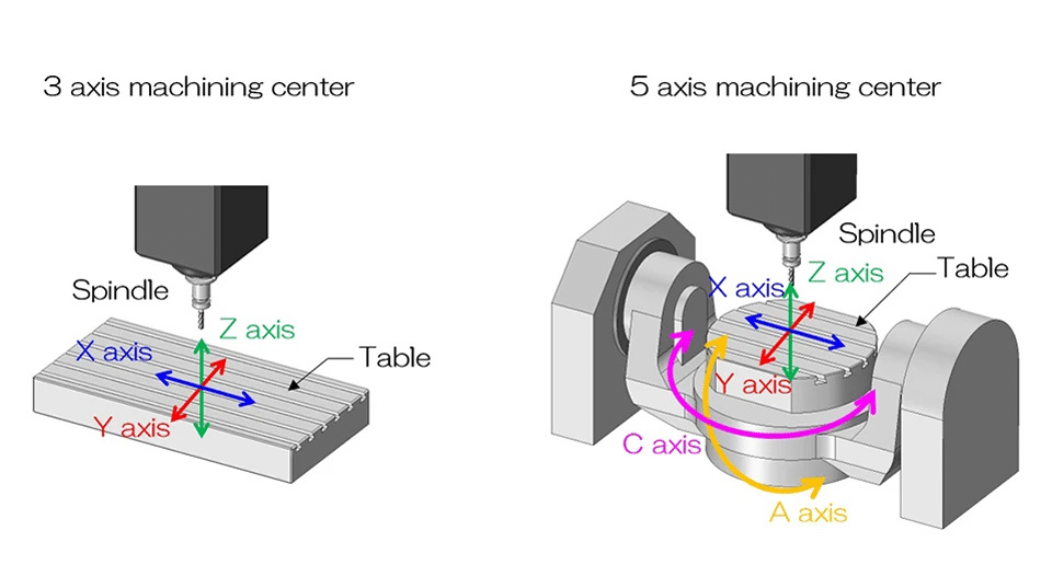
3-axis CNC machining uses X, Y, and Z linear movements with a fixed tool orientation. It is well suited to accessible pockets, holes, profiles, and contours. Features on other faces may require additional setups.
4-axis CNC machining adds one rotary axis, allowing the workpiece to be indexed to different positions or rotated during cutting. This is useful for multi-face components, circumferential features, and rotational profiles.
5-axis CNC machining adds two rotary axes, enabling access to inclined features and complex contours. Depending on the machine configuration, rotary movement comes from the table, spindle head, or both.
| Configuration | Cutting Movement | Suitable Applications | Key Consideration |
|---|---|---|---|
| 3-axis | X, Y, and Z linear movement | Pockets, brackets, plates, accessible contours | Multiple setups may be required |
| Indexed 4-axis (3+1) | Rotary positioning followed by 3-axis cutting | Multi-face parts, indexed hole patterns | Reduces manual repositioning |
| Simultaneous 4-axis | Coordinated linear and rotary movement | Helical features, wrapped profiles | Limited to one rotary axis |
| Indexed 5-axis (3+2) | Two-axis rotary positioning followed by 3-axis cutting | Angled holes, inclined faces, multi-sided parts | Tool orientation remains fixed during each cut |
| Simultaneous 5-axis | Coordinated movement of up to five axes | Impellers, complex contours, changing tool orientations | Requires advanced programming and collision verification |
More axes do not automatically produce more accurate parts. The appropriate configuration depends on tool accessibility, setup requirements, machine capability, and the dimensions that must be controlled.
Indexed vs. Simultaneous CNC Machining: Why the Distinction Matters
Indexed machining positions the workpiece or tool before cutting begins. Simultaneous machining coordinates rotary and linear movements during material removal. This distinction is often more useful than axis count alone when selecting a manufacturing process.
Indexed 4-Axis Machining vs. Simultaneous 4-Axis Machining
In indexed 4-axis machining, also called 3+1 machining, the additional rotary axis moves the workpiece to a programmed angle in a typical rotary-table configuration. The machine then performs a conventional three-axis operation. After completing those features, the rotary axis can index to another position.
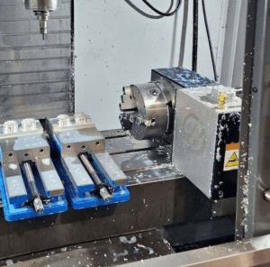
Consider a component with holes distributed around its perimeter. Indexing allows the machine to approach successive faces without requiring the operator to remove and manually reposition the workpiece for each orientation.
Simultaneous 4-axis machining is different. The rotary axis moves while the cutter removes material, enabling continuous paths around a workpiece. This can be appropriate for wrapped profiles, helical features, and other geometries requiring coordinated rotation.
Indexed 5-Axis Machining (3+2) vs. Simultaneous 5-Axis Machining
In 3+2 machining, two rotary axes establish the required workpiece-to-tool orientation. The cutter then machines the feature using three-axis movements while the rotary axes remain stationary.
This approach is particularly useful for angled holes, inclined surfaces, and features requiring several fixed compound-angle orientations.
Simultaneous 5-axis machining allows the tool orientation to change continuously along the cutting path. It becomes valuable when a fixed approach angle cannot provide the required access or tool engagement throughout the operation.
For example, complex blade passages may require the cutter to change orientation as it follows a contoured surface. An indexed position may not provide adequate access across the entire toolpath.
The important distinction is that a part requiring a 5-axis machine does not necessarily require simultaneous 5-axis cutting. Indexed machining can often provide the required access with less complex programming. Haas and Autodesk document both positional and simultaneous multi-axis workflows.
Which Part Geometries Are Best Suited to Each CNC Configuration?
The appropriate CNC configuration depends on the directions from which features must be machined. Geometric complexity alone is not enough to determine the required number of axes.
Accessible Features and Conventional 3-Axis Machining
Three-axis machining is well suited to components with features accessible from a fixed tool direction. Typical examples include mounting plates, brackets, fixtures, housings, and parts containing open pockets, slots, or straightforward drilled features.
It can also produce sophisticated three-dimensional surfaces using suitable tooling and CAM strategies. A contoured surface does not automatically require additional rotary axes if the cutter can reach it without interference.
For a component with features on opposing faces, separate setups may be practical. The decision depends on whether repositioning introduces significant labor, fixture requirements, or dimensional-control concerns.
Multi-Face and Rotational Features
Four-axis machining is useful when features are arranged around a common rotational direction.
Consider a housing with machined faces and drilled holes distributed around its perimeter. A 3-axis process may require the workpiece to be reclamped at different orientations. An indexed fourth axis could provide access to those features while maintaining the part in one fixture, provided the geometry and clearance permit it.
The main benefit is not necessarily a faster cutting operation. It is the potential reduction in manual handling, additional fixtures, and setup-related work.
Continuous rotary machining becomes more relevant when the required geometry follows the circumference of the workpiece rather than occupying separate indexed positions.
Compound Angles and Complex Contoured Surfaces
Five-axis machining becomes attractive when a component requires tool orientations that one rotary axis cannot provide efficiently.
Indexed 5-axis machining can access compound-angle holes, inclined pockets, and features distributed across different planes. Simultaneous 5-axis machining is more appropriate when the tool orientation must vary during the cut.
An impeller illustrates the distinction. Its curved blades and restricted passages can create tool-access challenges. Depending on the blade geometry, a simultaneous 5-axis toolpath may allow the cutter to follow the surface while adjusting its orientation to avoid interference and maintain suitable engagement.
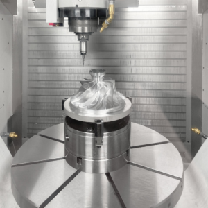
Even so, not every impeller or complex component requires simultaneous 5-axis machining. The decision depends on its actual geometry, cutter access, and manufacturing strategy.
How Do Tool Access, Workholding, and Setup Requirements Affect Machining?
Tool accessibility and workholding often determine whether additional CNC axes provide a practical advantage. Deep cavities, steep walls, and angled features can require long-reach cutters when the tool orientation is fixed. Greater tool overhang increases the risk of deflection, vibration, and poor surface finish.
Multi-axis machining can sometimes provide a more direct cutting approach, allowing shorter, more rigid tools. Seco Tools identifies minimizing tool overhang and maintaining rigidity as important measures for controlling milling deflection.
Fixture design can limit these benefits. Clamps, rotary tables, and tool holders must remain clear of the cutting path throughout the operation. Machining several faces in one setup can reduce repeated alignment and datum-setting errors, although surfaces blocked by the fixture may still require repositioning.
For indexed and simultaneous multi-axis operations, CAM-based machine simulation helps identify potential collisions, rotary-axis travel limits, and tool-clearance problems before machining begins.
Does More Axis Capability Improve Accuracy, Surface Finish, and Part Quality?
Five-axis machining is not inherently more accurate than three-axis machining. Dimensional quality depends on machine condition, geometric accuracy, cutting forces, tool rigidity, workholding, programming, and inspection.
Additional axes can improve access and reduce certain setup-related errors, but they also introduce rotary-axis relationships that require accurate calibration.
Geometry Creation and Dimensional Accuracy
A machine's ability to reach a feature is different from its ability to manufacture that feature within tolerance.
For example, a five-axis machine may access several inclined holes without reclamping. This can reduce the need to reestablish work coordinates between orientations, but the finished dimensions still depend on machining conditions and machine performance.
Research published through NIST identifies geometric, kinematic, thermal, and other machine-tool errors as important contributors to positioning accuracy. These factors must be controlled regardless of the number of axes.
Functional Features and Surface Finish
Producing the required geometry does not necessarily mean that every functional surface is finished to specification.
Precision bores, bearing seats, sealing faces, mating surfaces, and threads may require dedicated machining or finishing operations.
Surface finish also depends on cutter geometry, toolpath strategy, feed conditions, tool engagement, and vibration.
Multi-axis positioning may improve cutting conditions on difficult surfaces, but a properly optimized 3-axis operation can produce excellent results when the geometry is accessible.
Dimensional Inspection and Verification
Finished components must be verified against their engineering requirements.
Coordinate Measuring Machines (CMMs) can assess geometric features and dimensional relationships. In-process probing may assist with setup verification where the machine is appropriately equipped.
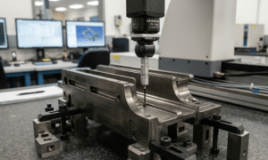
Machine calibration is another consideration. Renishaw documents methods for evaluating multi-axis machine performance, including rotary-axis kinematic accuracy under ISO 10791-6.
The machining strategy should therefore be evaluated alongside the inspection plan, particularly for components with critical interfaces or demanding feature relationships.
What Determines the Cost of 3-Axis, 4-Axis, and 5-Axis CNC Machining?
Total production cost matters more than machine hourly rates. The economical choice depends on part geometry, material, setup requirements, and production quantity.
3-axis machining is often cost-effective for accessible features requiring minimal repositioning. 4-axis machining can reduce handling and repeated setups for multi-face components. 5-axis machining may justify higher programming and machine costs when complex angles or contours would otherwise require multiple operations.
Key cost factors include:
- Programming and setup: CAM preparation, fixtures, and work offsets.
- Machining and tooling: Cutting time, material removal, tool wear, and tool changes.
- Handling and finishing: Repositioning, inspection, and secondary operations.
- Material and quantity: Machinability, stock costs, and batch size.
For prototypes, setup and programming can significantly influence unit cost. In repeat production, cycle time and process consistency become increasingly important.
A multi-axis machine can reduce total cost by consolidating operations, but simpler parts may gain little from the additional capability.
How to Choose the Right CNC Machining Process for Your Part
Selecting the appropriate CNC machining configuration begins with identifying the tool orientations required by the component.
A practical engineering decision follows these conditions:
- Choose 3-axis machining when the required features are accessible through conventional tool orientations and any additional setups remain efficient.
- Consider 4-axis machining when one rotary axis can simplify multi-face operations, circumferential features, or continuous rotational cutting.
- Consider indexed 5-axis machining when compound-angle features require additional fixed tool orientations.
- Consider simultaneous 5-axis machining when the cutter must change orientation during cutting to follow complex surfaces or maintain suitable access.
These choices must then be checked against the actual manufacturing requirements.
Can the fixture support the workpiece without obstructing critical features? Does the machine provide sufficient travel and rotary clearance? Are the required cutting tools suitable for the material and geometry? Can critical dimensions be verified reliably?
Engineers should also compare alternative manufacturing routes. A component may be technically feasible on several configurations, but setup time, tooling, quantity, and inspection requirements can make one approach more economical.
Before requesting a quotation, provide a complete CAD model and engineering drawing with the material grade, critical tolerances, surface-finish requirements, and expected production quantity.
This information allows the manufacturer to assess both geometric feasibility and the full production route.
Frequently Asked Questions
Can a 3-axis CNC machine produce angled holes using special fixtures?
Yes. An angled fixture can position the workpiece so the required hole aligns with the machine's available tool direction. This may require an additional setup, but it can be economical when the feature is straightforward and the fixture provides suitable stability.
When is a dedicated angled fixture more economical than indexed 5-axis machining?
A dedicated fixture may be more economical when a component requires only a limited number of fixed orientations, particularly if the fixture is reusable across production batches. The decision depends on fixture cost, programming effort, setup time, machine availability, and quantity.
What information should I provide when requesting a 3-axis, 4-axis, or 5-axis CNC machining quotation?
Provide a 3D CAD model, preferably in a widely supported exchange format such as STEP, along with a 2D engineering drawing. Specify the material grade, critical dimensions and tolerances, surface-finish requirements, inspection expectations, and production quantity. This helps the supplier recommend an appropriate machining process and prepare a meaningful quotation.
Conclusion
The choice between 3-axis, 4-axis, and 5-axis CNC machining should begin with the component's geometry and required tool access.
Three-axis machining remains effective for many accessible parts. Four-axis machining becomes useful when rotary movement simplifies multi-face or circumferential operations. Indexed 5-axis machining addresses compound-angle requirements, while simultaneous 5-axis machining is most valuable when tool orientation must change during cutting.
The final decision should also consider workholding, material, dimensional requirements, inspection, and total manufacturing cost.
BaiChuan Precision Manufacturing publishes 3-axis, 4-axis, and 5-axis CNC milling capabilities, along with material and inspection services. Engineers and procurement teams can submit their CAD models and drawings for a manufacturability review and quotation based on the component's specific requirements.
References
- Reader, J. (2026). 3-Axis vs. 5-Axis Machining. Autodesk Fusion.
- Singh, R. U. (2026). Benefits of 4-Axis Machining. Autodesk Fusion.
- Haas Automation. UMC — 5-Axis Machining for Everyone.
- DMG MORI. (2022). What Is 5-Axis Machining?.
- Seco Tools. Reduce Tool Deflection With a Short Reach.
- Gao, W., et al. (2023). Machine Tool Calibration. International Journal of Machine Tools and Manufacture.
- Renishaw. Using QC20 Ballbar for ISO 10791-6.
- BaiChuan Precision Manufacturing. CNC Milling Services.