
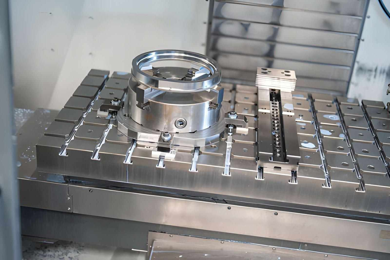
How to Prevent Deformation When Machining Large, Thin-Walled Workpieces
Preventing deformation when machining large, thin-walled workpieces requires careful control of cutting forces, heat, residual stresses, and clamping pressure. These components are particularly vulnerable to warping, bending, uneven surfaces, and dimensional errors because their thin sections cannot withstand machining loads as effectively as thicker parts. Even small changes in shape can cause a finished component to fall outside its required tolerances.
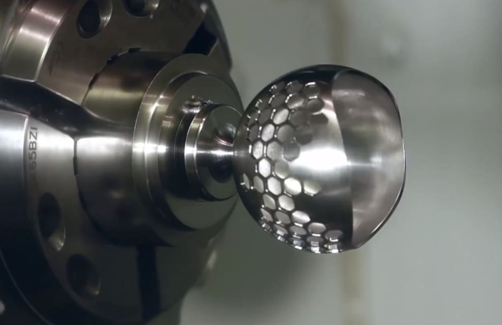
Manufacturers can reduce these risks by preparing materials correctly, removing material in stages, optimizing cutting parameters, and providing adequate support during machining. Careful temperature control and dimensional inspections between operations also help identify problems early, allowing manufacturers to make adjustments before final finishing.
Why Do Large, Thin-Walled Workpieces Deform During Machining?
Large, thin-walled workpieces deform when the forces and stresses inside the material become unbalanced or when cutting loads exceed the stiffness of the remaining structure. Several factors can contribute to this problem, and more than one may affect the same component.
Residual Stresses in the Material
Residual stresses are internal stresses that remain in a material even when no external force is applied. They can develop during casting, rolling, forging, welding, heat treatment, or previous machining operations.
When machining removes material, the remaining section must adjust to the change in stress balance. This can cause the workpiece to bend or warp, even if the cutting operation itself is stable. For example, milling a large aluminum plate into a thin frame may cause the frame to bow after material is removed from its center.
Cutting Forces
Cutting tools apply pressure to the workpiece as they remove material. Thick sections can usually resist these forces, but thin walls and large flat surfaces may flex under the same load.
This is especially common when machining deep pockets, narrow ribs, and thin webs. If the workpiece bends during cutting, it may return to a different shape after the tool passes or the component is unclamped.
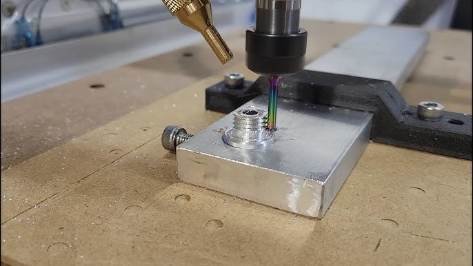
Heat Generation
Machining generates heat through friction between the cutting tool, workpiece, and chips. Uneven heating can cause different parts of the workpiece to expand at different rates, affecting dimensional accuracy.
For example, a large aluminum panel may develop flatness errors if one area becomes much hotter than the surrounding material. Temperature changes can also contribute to residual stresses that cause further deformation after machining. [1]
Improper Clamping
Clamping holds the workpiece in place during machining, but excessive or uneven pressure can distort thin sections before cutting begins. The machine may produce accurate dimensions while the part is clamped, only for the component to spring back into a different shape after removal.
Using suitable support and evenly distributed clamping forces helps reduce this risk.
Uneven Material Removal
Removing material unevenly can change the balance of internal stresses within a workpiece. Machining one side much more than the other may cause the component to bend as the remaining material adjusts.
Research on thin-walled aluminum components shows that both existing residual stresses and stresses created during machining can contribute to distortion. Controlling the depth of cut and machining sequence can help reduce these effects. [2]
Apply Solution Heat Treatment Before Machining
Solution heat treatment can help improve dimensional stability when machining certain heat-treatable alloys, particularly aluminum alloys. However, it must be selected according to the alloy type, initial material condition, and required mechanical properties. It is not a universal solution for every thin-walled component.
How Solution Heat Treatment Works
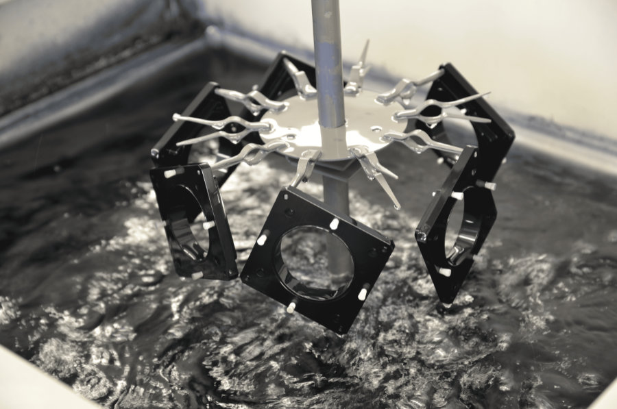
During solution heat treatment, an aluminum alloy is heated to a specified temperature to dissolve suitable alloying elements into the metal matrix. The material is then quenched at a controlled rate and may undergo artificial or natural aging to develop the required properties.
The correct temperature, holding time, and cooling process depend on the specific alloy. Incorrect treatment can affect strength, hardness, and dimensional stability.
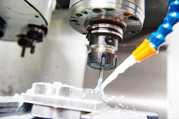
Choose the Right Stress-Relief Process
Solution heat treatment does not remove all residual stresses. Quenching can also introduce new stresses because the material cools unevenly. For this reason, manufacturers should consider the full heat-treatment route rather than relying on solution treatment alone.
Depending on the alloy and component requirements, suitable options may include:
- Stress-relieved material: Use a material grade and condition designed to reduce residual stresses before machining.
- Controlled heat treatment: Follow the specified solution treatment, quenching, and aging process when required for the alloy.
- Stress relief between machining stages: Consider an approved intermediate treatment when substantial material removal is likely to cause distortion.
Verify the Material Before Machining
Before selecting a treatment, confirm the alloy designation and its existing temper or heat-treated condition with the material supplier. This is especially important for aerospace components, where strength, fatigue resistance, and dimensional accuracy must meet strict requirements.
Research on aluminum workpieces shows that initial residual stresses and stresses created during machining can both contribute to distortion, even when the material has already undergone stress relief. [3]
For large, thin-walled parts, the best approach is to select a suitable material condition and approved treatment process before machining begins. A metallurgical engineer or material supplier can help determine whether additional heat treatment is appropriate for the component.
Use Staged Machining to Release Residual Stresses
Staged machining helps prevent deformation by removing material in controlled steps rather than completing the entire job in one operation. This approach gives the workpiece a chance to adjust as its shape and internal stress balance change. It is especially useful for large aluminum plates, thin frames, and components with deep pockets.
Rough Machine Before Finishing
Start by removing most of the unwanted material while leaving a suitable finishing allowance. Avoid machining the component to its final dimensions during the first operation, as later stress release may change its shape.
For example, when machining a large aluminum plate into a thin-walled housing, rough out the main pockets first. Leave enough material on the walls and base to allow for distortion before the final pass.
Allow the Workpiece to Stabilize
After rough machining, inspect the component for changes in flatness, wall thickness, and overall dimensions. If the material or component design is prone to significant distortion, an approved stress-relief treatment between machining stages may be appropriate.
The need for intermediate treatment depends on the alloy, the amount of material removed, and the required tolerances. It should not be applied automatically because some heat treatments can affect material properties or introduce further distortion.
Research into thin-walled aluminum machining shows that material removal can redistribute residual stresses and change the final shape of a component. A staged process helps manufacturers identify these changes before precision finishing. [4]
Balance Material Removal Across Both Sides
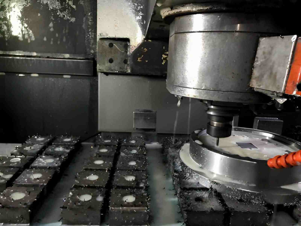
Where the component design allows, remove material from opposite sides in a balanced sequence. This can help reduce uneven stress release and limit bending. For thin walls, alternating machining between sides may also help control distortion.
However, the best sequence depends on the component's geometry and stress distribution. Research on thin-walled aluminum components has shown that machining paths and cutting strategies can affect residual stresses and the amount of deformation after machining. [5]
Complete the Final Finishing Pass
Perform final finishing only after major material removal and any required stress-relief operations. Use a consistent finishing allowance and inspect the workpiece before the final pass.
This approach reduces the risk of discovering significant distortion after the component has already reached its final dimensions.
Reduce Cutting Speed and Optimize Machining Parameters
Choose cutting parameters that control heat and cutting forces without making the machining process unstable. Cutting speed, feed rate, depth of cut, tool geometry, and workpiece thickness all affect how a thin-walled component behaves during machining.
Simply using the lowest possible cutting speed is not always effective. The goal is to maintain stable cutting conditions while limiting heat buildup, vibration, and excessive pressure on unsupported sections.
Adjust Cutting Speed, Feed Rate, and Depth of Cut
Each cutting parameter affects the machining process differently.
- Cutting speed: Lowering the speed may reduce heat generation under certain conditions, but it can also increase cutting forces or cause poor cutting action if the tool is not suited to the new speed.
- Feed rate: An appropriate feed rate helps the tool cut cleanly without placing excessive pressure on thin walls. An unsuitable feed rate can increase tool wear, vibration, or surface defects.
- Depth of cut: Reducing the depth of cut can limit the load applied during each pass. This is useful when machining thin ribs, narrow walls, and deep pockets that have limited support.
For example, when milling a thin aluminum wall, a large depth of cut may cause the wall to flex away from the tool. Reducing the cutting load and choosing a suitable tool path can help maintain the required wall thickness.
Use Sharp Tools and Suitable Tool Paths
A sharp cutting tool reduces unnecessary friction and helps remove material cleanly. Worn tools can increase cutting forces, generate more heat, and produce poor surface finishes.
Tool paths also affect how forces act on thin sections. Choose a path that maintains stable tool engagement and avoids sudden changes in cutting load. Where possible, use smooth entry and exit movements to reduce the risk of vibration or local deformation.
Research on thin-wall milling has found that cutting parameters affect cutting forces, surface quality, and dimensional errors. The best settings depend on the material and wall geometry, so manufacturers should test and adjust them rather than rely on one fixed set of values. [6]
Ensure Effective Chip Removal
Chips trapped between the tool and workpiece can increase friction and damage the finished surface. Use suitable coolant or air to clear chips from deep pockets and narrow spaces. The method should match the material, tool, and machining process.
For precision components, confirm the cutting parameters through trial cuts and dimensional checks before machining the full workpiece.
Improve Workholding and Support for Thin Sections
Proper workholding prevents thin-walled workpieces from bending or vibrating under cutting forces. The fixture must hold the component securely without applying excessive pressure or restricting its natural movement as material is removed.
This is especially important when machining large panels, thin ribs, and deep pockets. Even a small amount of clamping distortion can lead to dimensional errors after the workpiece is released.
Apply Even Clamping Pressure
Distribute clamping forces across suitable contact points rather than applying high pressure to a few small areas. Position clamps where the component has enough stiffness to resist the load, and avoid placing them directly against unsupported thin walls.
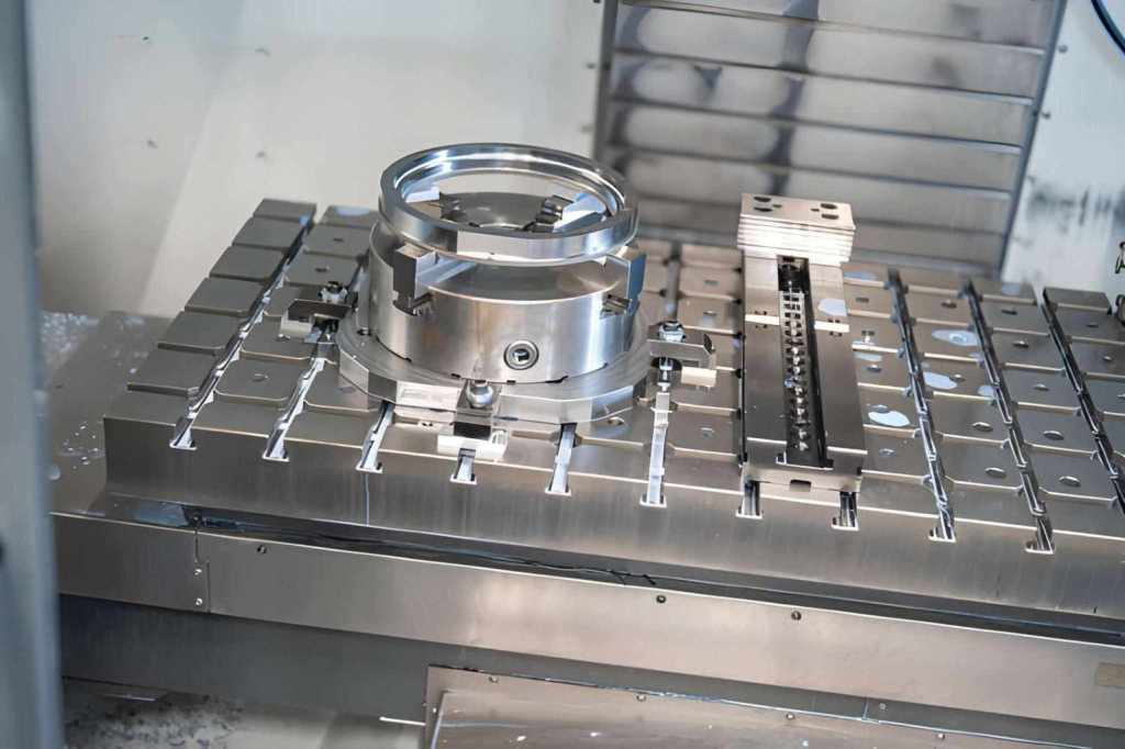
For example, clamping a thin aluminum plate tightly at its corners may cause it to bow. The machine could then cut a flat surface that becomes uneven when the plate is unclamped.
Use Suitable Fixtures and Supports
The right fixture depends on the workpiece's size, shape, material, and machining requirements. Common options include:
- Backing plates: Support large, flat workpieces and reduce bending during machining.
- Vacuum fixtures: Hold suitable thin panels across a wider area without concentrated mechanical clamping forces. Their effectiveness depends on the seal, vacuum level, and cutting loads.
- Custom supports: Provide support beneath thin walls, ribs, and other flexible areas close to the cutting zone.
- Dedicated fixtures: Position complex components consistently and provide support at selected points throughout the machining process.
Research on thin-walled machining highlights the importance of workpiece stiffness and clamping conditions in controlling deformation. Fixture design should therefore match the component's geometry and the forces expected during cutting. [7]
Check the Workpiece After Unclamping
Always inspect the component after releasing the clamps. A thin-walled part may appear accurate while secured in the fixture but spring back once the clamping force is removed.
Measure flatness, wall thickness, and other critical dimensions against the engineering drawing. If the part shows repeated distortion, review the clamp positions, support points, and clamping force before the next machining run.
Studies on fixture design show that optimizing support locations and clamping forces can reduce workpiece deflection and improve machining accuracy. [8]
Best Practices for Preventing Deformation
Preventing deformation in large, thin-walled workpieces requires a combination of material preparation, controlled machining, and proper support. The following practices help manufacturers maintain dimensional accuracy and reduce the risk of rework.
Prevent Deformed Parts During Aluminum Machining
- Select the right material condition: Confirm the alloy, temper, and heat-treatment history before machining.
- Apply suitable stress relief: Use an approved stress-relief process when residual stresses are likely to affect dimensional stability.
- Remove material in stages: Rough machine first, allow the workpiece to stabilize, and finish only after major material removal.
- Balance material removal: Machine both sides in a planned sequence where the component design allows.
- Leave a finishing allowance: Retain enough material during rough machining to correct small dimensional changes later.
- Use stable workholding: Distribute clamping forces and support thin sections close to the cutting zone.
- Optimize cutting parameters: Select suitable cutting speeds, feed rates, depths of cut, and tool paths for the material and wall thickness.
- Control temperature: Use suitable cooling methods and allow the workpiece to stabilize before precision finishing.
- Inspect between operations: Check critical dimensions after rough machining and before final finishing.
These practices work best when combined in a planned machining process. Research on thin-walled components shows that residual stresses, cutting conditions, and workholding can all affect final deformation. Addressing these factors together helps manufacturers achieve more consistent results.
Conclusion
Preventing deformation when machining large, thin-walled workpieces requires careful control of residual stresses, cutting forces, heat, and clamping pressure. Preparing the material correctly, removing material in stages, optimizing cutting parameters, and providing adequate support can help maintain dimensional accuracy throughout the process.
Solution heat treatment and intermediate stress relief should be selected according to the material and component requirements. Manufacturers should also inspect dimensions between machining stages and check the workpiece after unclamping. A well-planned machining process reduces distortion, limits rework, and helps produce components that meet the required tolerances.
References
Hasçelik, A., Aslantas, K., & Yalçın, B. (2025). Optimization of cutting parameters to minimize wall deformation in Micro-Milling of Thin-Wall geometries. Micromachines, 16(3), 310. https://doi.org/10.3390/mi16030310
Li, B., Jiang, X., Yang, J., & Liang, S. Y. (2014a). Effects of depth of cut on the redistribution of residual stress and distortion during the milling of thin-walled part. Journal of Materials Processing Technology, 216, 223–233. https://doi.org/10.1016/j.jmatprotec.2014.09.016
Li, B., Jiang, X., Yang, J., & Liang, S. Y. (2014b). Effects of depth of cut on the redistribution of residual stress and distortion during the milling of thin-walled part. Journal of Materials Processing Technology, 216, 223–233. https://doi.org/10.1016/j.jmatprotec.2014.09.016
Liu, H., Wang, C., Li, T., Bo, Q., Liu, K., & Wang, Y. (2022). Fixturing technology and system for thin-walled parts machining: a review. Frontiers of Mechanical Engineering, 17(4). https://doi.org/10.1007/s11465-022-0711-5
Wang, F., Cheng, X., Zheng, G., Yang, X., Guo, Q., & Sun, Q. (2018). Study of micromilling parameters and processes for thin wall fabrications. Precision Engineering, 56, 246–254. https://doi.org/10.1016/j.precisioneng.2018.12.005
Weber, D., Kirsch, B., Chighizola, C. R., D'Elia, C. R., Linke, B. S., Hill, M. R., & Aurich, J. C. (2021). Analysis of machining-induced residual stresses of milled aluminum workpieces, their repeatability, and their resulting distortion. The International Journal of Advanced Manufacturing Technology, 115(4), 1089–1110. https://doi.org/10.1007/s00170-021-07171-7
Wu, Q., Wu, J., Zhang, Y., Gao, H., & Hui, D. (2019). Analysis and homogenization of residual stress in aerospace ring rolling process of 2219 aluminum alloy using thermal stress relief method. International Journal of Mechanical Sciences, 157–158, 111–118. https://doi.org/10.1016/j.ijmecsci.2019.04.040
Zawada-Michałowska, M., & Pieśko, P. (2026). Analysis of machining strategies in terms of residual stress and post-machining deformation of thin-walled element. The International Journal of Advanced Manufacturing Technology, 142(5–6), 2335–2358. https://doi.org/10.1007/s00170-025-17176-1