
CNC Tool Nose Radius Compensation: G-Code Examples and Common Mistakes
CNC tool nose radius compensation helps maintain dimensional accuracy and surface quality when turning parts with tapers, arcs, chamfers, and complex profiles. The cutting tip of a turning insert has a rounded edge rather than a perfect point. If the CNC program does not account for this radius, the tool may remove too much or too little material, resulting in incorrect dimensions and contour errors.
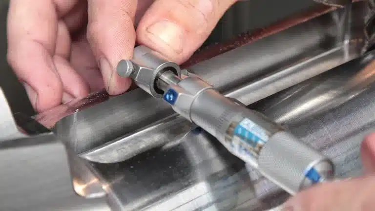
CNC Tool Nose Radius Compensation
By applying the correct compensation settings, machinists can improve profile accuracy and reduce the need for repeated adjustments. This guide explains how CNC tool nose radius compensation works, how to program it using G-code, and how to manage tool offset tables. It also covers common programming errors and practical methods for checking and correcting compensation problems before they affect production.
What Is CNC Tool Nose Radius Compensation?
CNC tool nose radius compensation adjusts the tool path to account for the rounded tip of a turning insert. It helps the cutting edge follow the intended part profile, especially when machining tapers, arcs, chamfers, and other angled surfaces. Without correct compensation, the finished part may differ from the dimensions in the engineering drawing. [1]
Why Does the Tool Nose Radius Matter?
A turning insert has a rounded tip with a specific radius, such as 0.4 mm, 0.8 mm, or 1.2 mm. The CNC program often defines the intended contour using theoretical tool-tip coordinates. However, the actual cutting edge extends around the rounded tip, so its position does not always match that theoretical point.
This difference becomes important when the tool moves across an angled or curved surface. For example, when turning a tapered shaft, the rounded insert tip can remove more or less material than intended if the controller does not calculate the correct tool path.
Common Tool Nose Radius Compensation Commands
CNC lathes commonly use three G-code commands to control tool nose radius compensation:
| G-code | Function |
|---|---|
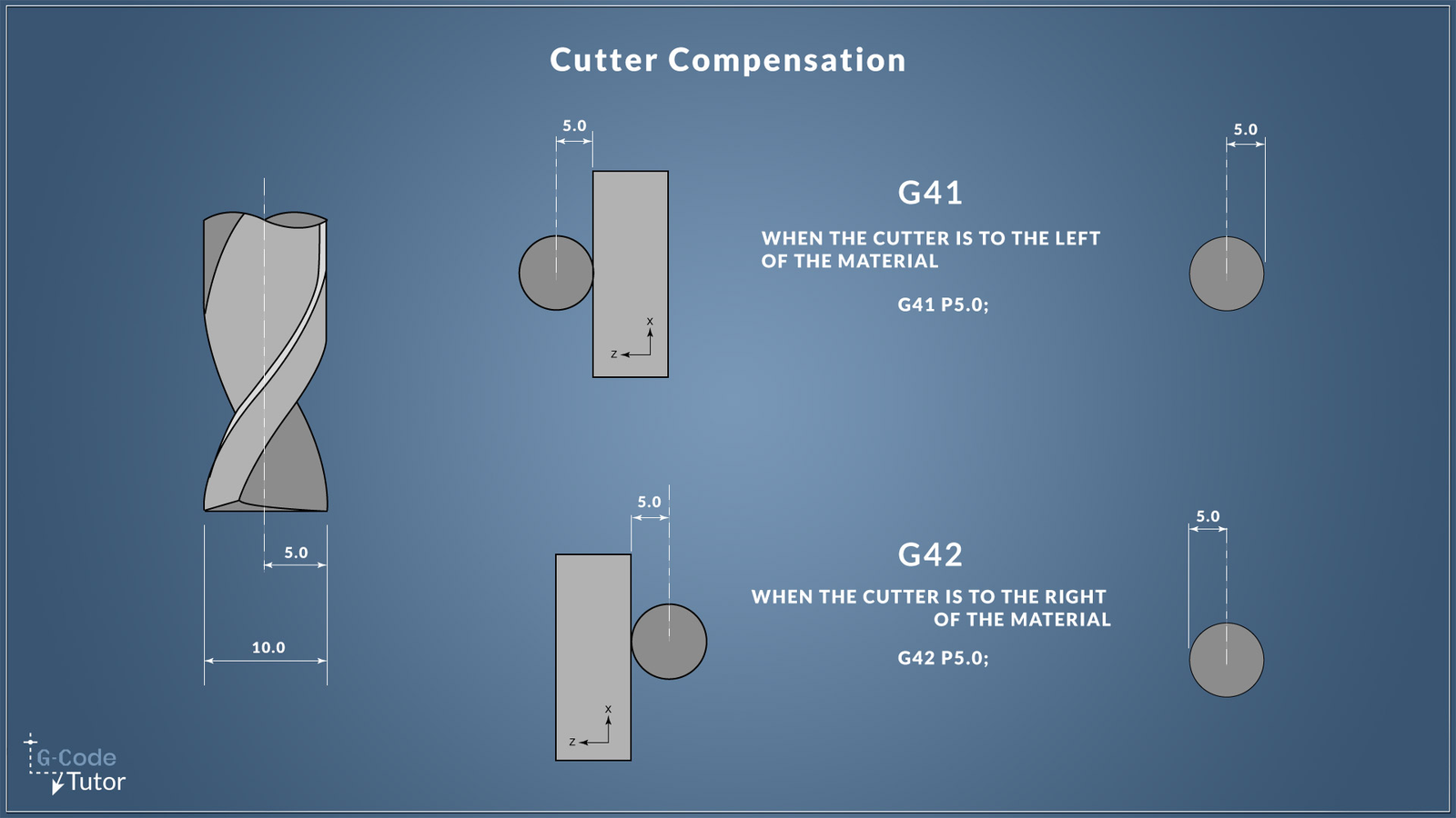
| G41 | Applies tool nose radius compensation to the left of the programmed path. |
| G42 | Applies tool nose radius compensation to the right of the programmed path. |
| G40 | Cancels tool nose radius compensation. |
The meaning of left and right depends on the programmed direction of travel and the CNC control's conventions. The correct command also depends on the tool orientation and cutting setup. Always check the machine's programming manual before selecting G41 or G42. [2]
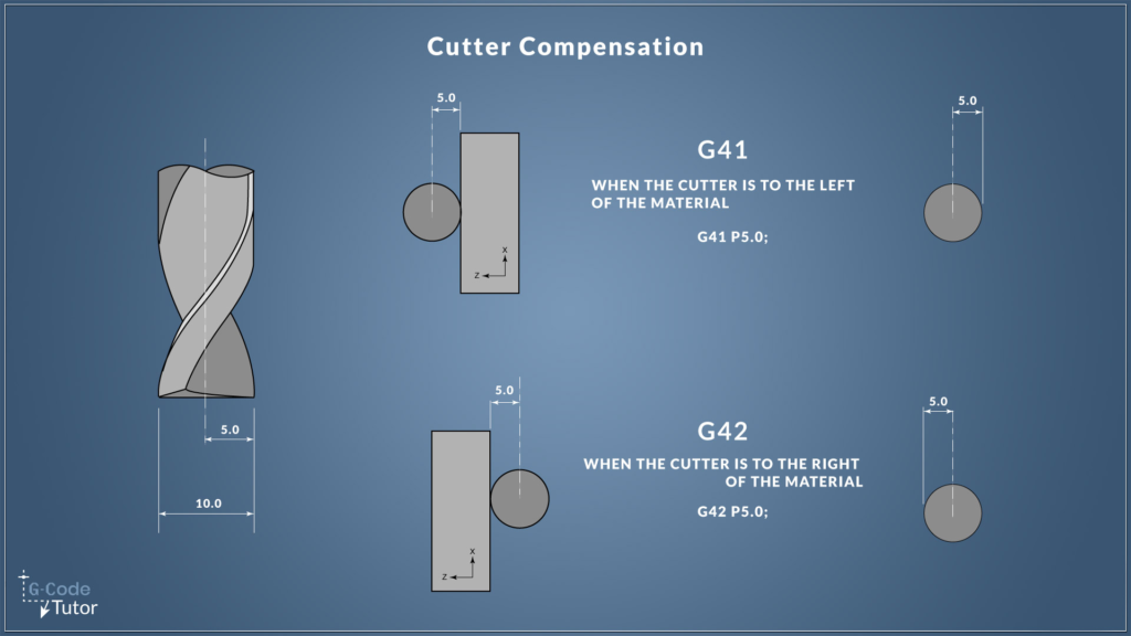
G41 and G42 cutter compensation
Programmed Tool Path vs. Actual Cutting Edge
The programmed tool path represents the intended part contour, while the controller calculates the adjusted path needed to account for the insert's nose radius. This allows the cutting edge to produce the required profile rather than simply following the programmed coordinates with its rounded tip.
For example, a drawing may specify a tapered surface that connects to a straight diameter. Without correct compensation, the transition may develop a dimensional error even when the programmed coordinates are correct. Proper compensation helps the insert follow the intended contour more accurately.
How CNC Tool Nose Radius Compensation Works
CNC tool nose radius compensation works by adjusting the tool path according to the insert's nose radius and tool orientation. The controller uses these settings to calculate the cutting position needed to follow the programmed contour. This is especially important when turning tapers, arcs, chamfers, and profiles that combine straight and curved surfaces.
How the CNC Controller Calculates Compensation
When compensation is active, the controller calculates an offset between the programmed contour and the actual cutting edge. The size and direction of this adjustment depend on the nose radius, tool orientation, and programmed path.
For example, consider a turning insert with a nose radius of 0.8 mm. When machining a tapered shaft, the controller must account for the rounded tip as the tool moves along the angled surface. Entering the correct radius allows it to calculate the required tool movement more accurately.
Tool Geometry Offsets vs. Nose Radius Compensation
Tool geometry offsets and nose radius compensation serve different purposes. Geometry offsets define the tool's position relative to the machine's reference point, while nose radius compensation adjusts the cutting path to account for the rounded insert tip.
| Setting | Purpose |
|---|---|
| X geometry offset | Defines the tool's position along the X-axis. |
| Z geometry offset | Defines the tool's position along the Z-axis. |
| Nose radius offset | Stores the insert's nose radius for compensation calculations. |
| Tool orientation | Identifies the direction of the tool tip relative to the insert geometry. |
| Wear offset | Makes small corrections to compensate for wear or dimensional errors. |
The exact field names and offset conventions vary by CNC control. On many lathes, X geometry values are displayed as diameters, so machinists must also understand whether the control uses diameter or radius programming.
Why Tool Orientation Matters
The controller needs the correct tool orientation to determine how the rounded tip relates to the programmed contour. If the orientation setting does not match the actual tool setup, the controller may calculate the wrong compensation direction or amount.
For example, if an external turning tool is set up with an incorrect tip orientation, the finished taper may not match the drawing even when the nose radius is entered correctly. Checking the insert position and orientation before machining helps prevent these errors. [3]
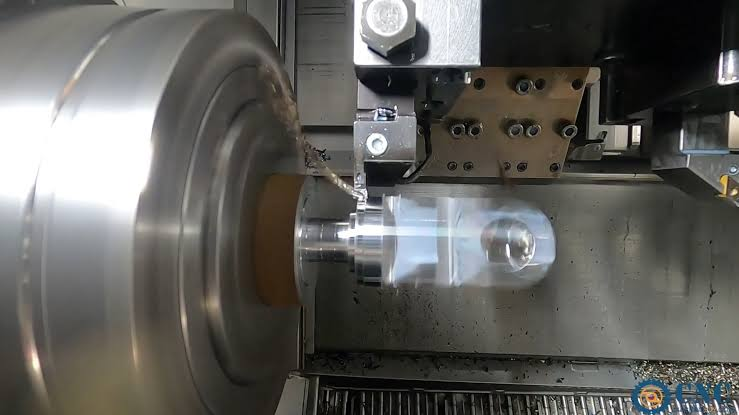
Example of an Incorrect Compensation Setting
Suppose a drawing specifies a tapered surface that must meet a straight diameter at a precise point. The machinist enters a nose radius of 0.4 mm, but the installed insert has a radius of 0.8 mm.
The controller calculates the compensated path using the smaller value. As a result, the cutting edge may not follow the intended contour, leading to profile errors near the taper or transition. The correct response is to verify the installed insert, check the offset table, and confirm the tool orientation before changing the program.
The key point: Accurate compensation depends on matching the programmed contour, nose radius, tool orientation, and offset settings to the actual machining setup.
CNC Tool Nose Radius Compensation G-Code Examples
CNC tool nose radius compensation uses G41 or G42 to adjust the tool path while machining a profile. The program must include a suitable approach move before compensation starts and a safe exit move before it is canceled. The exact syntax and behavior depend on the CNC control, so verify each example against the machine's programming manual before use.
Basic G-Code Example for CNC Turning
The following example shows the general structure of a compensated external turning operation. It uses illustrative coordinates and assumes a compatible FANUC-style lathe control. The correct compensation direction and tool offset format must be confirmed for the specific machine.
%
O0100 (EXTERNAL TURNING WITH NOSE RADIUS COMPENSATION)
G21 G18 G40 G99
T0101
G97 S800 M03
G00 X42.0 Z3.0
G01 G42 X40.0 Z0.0 F0.15
G01 Z-20.0
G01 X30.0 Z-30.0
G01 Z-40.0
G01 G40 X32.0 Z-42.0
G00 X100.0 Z100.0
M30
%
Important: This is an illustrative program, not a ready-to-run machining program. Confirm the tool orientation, compensation direction, offset format, clearance, and lead-in and lead-out moves for your specific machine before use.
Understanding the G-Code Program
Each command controls a part of the turning operation. The following table explains the main lines.
| G-code | Purpose |
|---|---|
| G21 | Sets metric units. |
| G18 | Selects the XZ plane used for lathe operations. |
| G40 | Ensures nose radius compensation is canceled before the operation starts. |
| G99 | Selects feed per revolution on controls that use this convention. |
| T0101 | Selects tool 1 with its associated offset, using this control's format. |
| G97 S800 M03 | Sets a constant spindle speed of 800 rpm and starts the spindle clockwise. |
| G00 X42.0 Z3.0 | Moves the tool rapidly to the approach position. |
| G01 G42 X40.0 Z0.0 F0.15 | Starts a feed move while requesting right-side compensation. |
| G01 Z-20.0 | Turns along the Z-axis to the next contour point. |
| G01 X30.0 Z-30.0 | Machines an angled transition to a smaller diameter. |
| G01 Z-40.0 | Continues turning along the straight section. |
| G01 G40 X32.0 Z-42.0 | Requests compensation cancellation during the exit move. |
| G00 X100.0 Z100.0 | Retracts the tool to a clearance position, if safe for the machine setup. |
| M30 | Ends the program and resets it for another run. |
The example uses diameter programming for X coordinates and assumes the control accepts these commands in this format. Actual tool selection, spindle direction, compensation activation, and cancellation may differ between machines. [4]
How Nose Radius Compensation Improves Taper Accuracy
Consider a shaft that has a 40 mm diameter section connected to a 30 mm diameter section by a taper. The taper begins at Z-20 and ends at Z-30 in the example program.
Without correct nose radius compensation, the rounded insert tip may not follow the intended transition accurately. The result can be an incorrect taper profile or a poor connection between the straight and angled surfaces.
Tool Nose Radius Compensation in Precision CNC Turning
With the correct radius and orientation entered in the offset table, the controller can calculate the required tool path. This helps the cutting edge follow the programmed contour more closely. Research on tool nose radius compensation also highlights the need to account for tool geometry when machining accurate profiles.
Choosing the Correct Compensation Direction
The choice between G41 and G42 depends on the direction of tool travel, the tool orientation, and the controller's programming conventions. Do not select a command based only on whether the operation is external or internal turning.
Before running the program:
- Confirm the tool orientation setting in the offset table.
- Check whether the programmed contour and tool movement require G41 or G42.
- Ensure the lead-in move gives the controller enough distance to apply compensation.
- Provide a suitable lead-out move before canceling compensation with G40.
- Simulate the program and check for interference before cutting the actual part.
Short or unsuitable lead-in moves may trigger compensation alarms or cause unexpected tool movement. The required clearance depends on the insert radius, contour geometry, and controller. [5]
Always verify the complete tool path before machining. A program that looks correct on screen may still cause a collision if the tool orientation, workpiece position, or offset values do not match the actual setup.
Understanding CNC Tool Compensation Tables and Offset Settings
CNC tool compensation tables store the measurements and settings the controller needs to position the cutting tool correctly. For accurate CNC tool nose radius compensation, machinists must enter the correct nose radius, tool geometry offsets, and tool orientation. Incorrect values can lead to dimensional errors even when the G-code follows the intended contour.
Common Tool Offset Table Settings
A typical CNC lathe offset table includes several fields that control tool position and compensation.
| Offset setting | Purpose | Example |
|---|---|---|
| Tool number | Identifies the cutting tool | Tool 1 |
| X geometry offset | Sets the tool position along the X-axis | 150.250 mm |
| Z geometry offset | Sets the tool position along the Z-axis | 320.600 mm |
| Nose radius | Defines the radius of the insert tip | 0.8 mm |
| Tool orientation | Identifies the tool tip direction | Orientation 3 |
| X wear offset | Applies a small correction to the X position | -0.02 mm |
| Z wear offset | Applies a small correction to the Z position | +0.01 mm |
These values are illustrative, not recommended settings for a particular machine. Tool orientation numbers, offset formats, and the sign conventions for geometry and wear corrections vary between CNC controls.
How to Enter and Verify the Nose Radius
Before enabling compensation, check the insert manufacturer's specifications or packaging to confirm the nose radius. Common values include 0.4 mm, 0.8 mm, and 1.2 mm, although other sizes are available.
Follow these steps:
- Check the installed insert. Confirm that its nose radius matches the tool setup and machining plan.
- Enter the radius in the correct field. Use the field intended for nose radius compensation, not an X or Z geometry field.
- Verify the tool orientation. Make sure the selected orientation matches the actual tool position.
- Check the geometry offsets. Confirm that the X and Z values correctly locate the tool relative to the machine reference.
- Review the wear offsets. Ensure that previous corrections will not cause an unexpected dimensional shift.
Geometry Offsets vs. Wear Offsets
Geometry offsets establish the tool's measured position. Wear offsets allow small corrections after machining and inspection.
Nose radius in tool designations
For example, suppose a turned diameter measures 40.04 mm when the target is 40.00 mm. A machinist may need to adjust the X wear offset, depending on the control's sign convention and whether X values use diameter or radius programming. The correct adjustment should be based on the measured error and the machine's offset rules.
Do not use wear offsets to compensate for an incorrect nose radius or tool orientation. Correct the underlying setup first, then use wear offsets for small, controlled adjustments.
Best practice: Record proven tool geometry, nose radius, orientation, and wear corrections for repeat jobs. This makes setup checks easier and helps reduce errors when replacing inserts or setting up another batch of parts. [6]
Best Practices for Accurate Tool Nose Radius Compensation
Accurate CNC tool nose radius compensation depends on correct tool settings, suitable tool paths, and careful verification. Follow these practices to reduce machining errors and maintain consistent part quality.
- Verify the insert radius and tool orientation before entering compensation values.
- Use suitable lead-in and lead-out moves to allow safe compensation activation and cancellation.
- Keep geometry and wear offsets separate to avoid compounding dimensional errors.
- Check the G41 and G42 direction against the programmed contour and controller conventions.
- Simulate the tool path to identify possible interference or incorrect movements.
- Inspect the first machined part and make measured, controlled wear-offset corrections where needed.
- Record proven settings for repeat jobs and future tool setups.
Conclusion
CNC tool nose radius compensation helps machinists produce accurate profiles when turning tapers, arcs, chamfers, and complex contours. Correct use of G41, G42, and G40, along with accurate tool radius and orientation settings, helps the cutting edge follow the intended contour and reduces dimensional errors.
To achieve consistent results, verify the tool offset table, use suitable lead-in and lead-out moves, and simulate the program before machining. Inspect the first finished part and make controlled wear-offset adjustments based on measured results. These practices help reduce machining errors, improve surface quality, and maintain dimensional accuracy across production runs.
References
Dejan. (2026, February 5). G-Code explained | List of most important G-Code commands. How to Mechatronics. https://howtomechatronics.com/tutorials/g-code-explained-list-of-most-important-g-code-commands/
Gao, Z. X. (2015). The analysis and the application of tool Nose round radius compensation based on FANUC NC system. Applied Mechanics and Materials, 727–728, 656–659. https://doi.org/10.4028/www.scientific.net/amm.727-728.656
Marc. (n.d.). G41 and G42 cutter compensation. GCodeTutor. https://gcodetutor.com/gcode-tutorial/g41-g42-cutter-compensation.html
Tool compensation. (n.d.). https://linuxcnc.org/docs/html/gcode/tool-compensation.html
Tool Offset: setup, types & best practices. (2026, July 16). https://jlccnc.com/blog/tool-offset
Mastering GCode G41, G42, and G40: Tool Compensation Power. (n.d.). https://www.cnccookbook.com/mastering-gcode-g41-and-g42-tool-compensation-power/