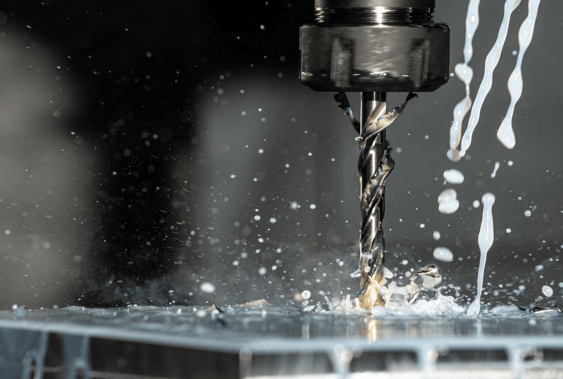
The automotive industry demands a manufacturing process that can deliver precision, consistency, and scalability across everything from one-off prototypes to millions of production parts. CNC machining meets all three requirements, making it one of the most widely used fabrication methods in vehicle development and production. Whether producing a first-article prototype for engineering validation or machining brake calipers in high-volume production runs, CNC technology provides the dimensional accuracy and process repeatability that automotive safety and performance standards require.
CNC Machining Within the Automotive Industry
Role of CNC Machining in Automotive Manufacturing
CNC machining occupies a central position in automotive manufacturing, producing components that manual machining cannot deliver at the required accuracy, speed, or consistency. As vehicle designs grow more complex and safety regulations become more stringent, the role of CNC in automotive production has expanded rather than diminished, even as casting, forging, and stamping handle the highest-volume commodity parts.
What CNC Machining Does in Automotive Production
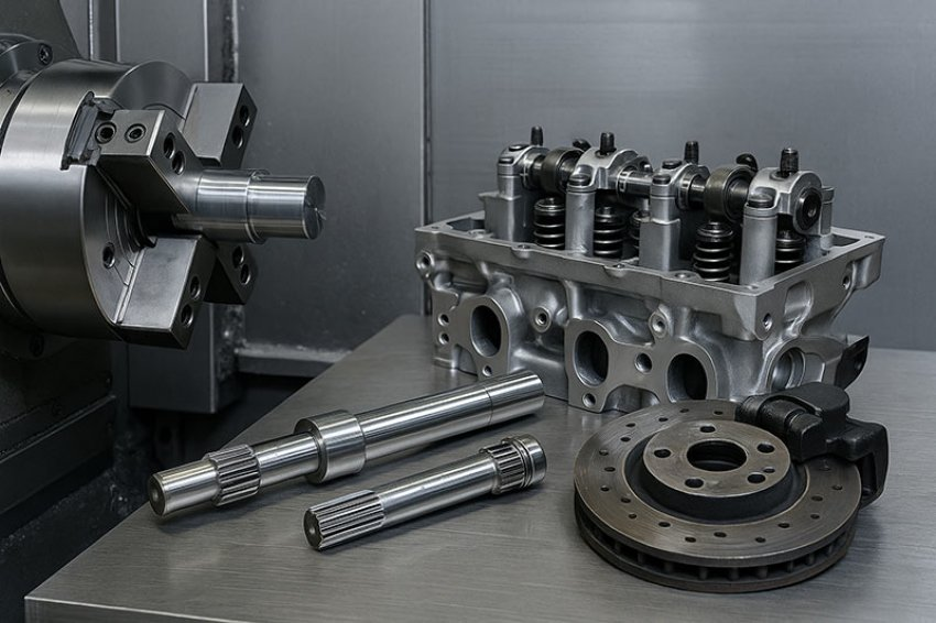
CNC machining removes material from metal or plastic stock to produce components with precise geometry, tight tolerances, and specified surface finishes. In automotive manufacturing, it is applied across multiple vehicle systems:
- Engine components: Cylinder heads, engine blocks, crankshaft journals, camshaft bearing surfaces, and intake manifolds are all machined to tight tolerances that govern compression, sealing, and bearing performance.
- Transmission and gearbox components: Gear bores, shaft seats, housing mating faces, and valve body passages require dimensional accuracy that determines shift quality, load capacity, and service life.
- Chassis and suspension parts: Suspension uprights, control arm mounts, and steering components are machined to ensure correct geometry and alignment across the vehicle's dynamic range.
- Braking system components: Brake calipers, master cylinder bores, and rotor mounting faces require precise geometry for consistent braking force and safe operation under thermal and mechanical stress. [1]
Why CNC Is Preferred Over Manual Machining
Manual machining relies on operator skill and judgment to achieve dimensional accuracy, introducing variability that is incompatible with automotive production requirements. CNC machining replaces operator judgment with programmed precision, delivering:
- Consistent tolerances across every part in a batch, regardless of operator experience or fatigue
- Faster cycle times through optimized toolpaths, automated tool changes, and continuous spindle utilization
- Reduced human error in dimension-critical operations where a deviation of tens of microns can affect component function or safety
Key Requirements in Automotive Parts
Automotive components place three non-negotiable demands on the machining process: tight tolerances to ensure correct fit and function, surface integrity to support fatigue life and sealing performance, and batch consistency to guarantee that every part across a production run performs identically. A gearbox housing, for example, must hold bore positions and diameters accurately enough to ensure correct gear mesh geometry across thousands of units, with no part-to-part variation that would affect transmission noise, efficiency, or durability. [2]
CNC Machining for Automotive Prototypes
Prototyping is where automotive development begins, and CNC machining is the dominant method for producing functional prototype parts quickly and accurately. Before a component enters production tooling, it must be validated dimensionally, structurally, and functionally, and CNC machining provides the fastest path from a CAD model to a physical part ready for testing.
What is CNC Prototype Machining
Importance of Prototyping in Vehicle Development
Automotive development programs operate under intense time and cost pressure. A design flaw identified during prototype testing costs a fraction of what the same flaw would cost if discovered after production tooling has been committed. Physical prototypes allow engineers to verify fit within the assembly, test structural performance under load, and identify design issues that simulation alone may not reveal. CNC machining compresses the time between design intent and physical validation, supporting faster development cycles across the entire vehicle program. [3]
How CNC Converts CAD Designs into Physical Parts
A CAD model can be translated into a CNC toolpath and a machined part within hours of design completion. The process requires no dedicated tooling, no molds, and no minimum batch size, making it uniquely suited to the one-off and small-batch quantities typical of prototype programs. Changes to the design are implemented by modifying the CAD model and regenerating the toolpath, allowing multiple design iterations to be evaluated in the time it would take to produce a single cast or forged prototype.
Faster Design Testing and Iteration
The speed of CNC prototyping directly compresses development timelines:
- A suspension bracket design can be machined, installed, tested on a rig, modified based on test results, and re-machined within days rather than weeks.
- Multiple design variants can be produced simultaneously and tested in parallel, providing comparative data that a single prototype cannot deliver.
- Functional prototypes machined from the same material specified for production give engineers accurate structural and surface performance data, unlike rapid prototyping methods that use substitute materials.
Benefits of CNC Prototyping
- Cost savings: Identifying and correcting design flaws before production tooling is committed avoids the high cost of tooling modifications or scrapped dies.
- Reduced development time: Faster iteration cycles compress the overall development program timeline, accelerating time to market.
- Design validation: CNC prototypes machined to production tolerances provide reliable validation data that supports engineering sign-off and regulatory submissions. [4]
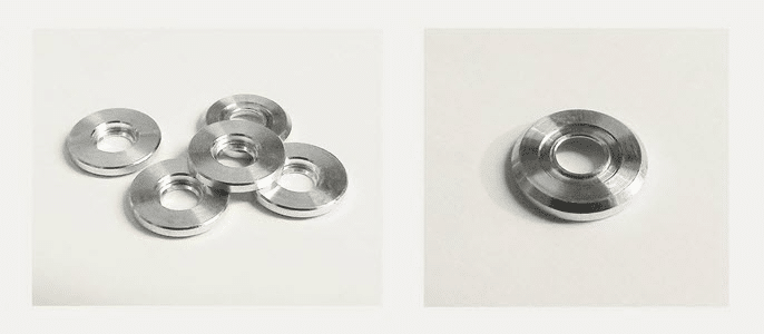
A representative example is a prototype suspension bracket for a new vehicle platform. The bracket is CNC machined from the specified aluminum alloy, installed on a test rig, and subjected to representative load cycles. Any design modifications identified during testing are incorporated into the CAD model, and a revised prototype is machined within days, allowing the development program to progress without waiting for cast or forged prototype tooling.
Material Selection for Automotive CNC Parts
Material selection in automotive CNC machining is a balance between performance, weight, machinability, and cost. The material chosen for a component determines not only its mechanical behavior in service but also the cutting parameters, tooling, and cycle time required to produce it. In an industry where weight reduction, durability, and cost efficiency are simultaneously pursued, material decisions carry significant engineering and economic consequences.
Common Materials Used in Automotive CNC Machining
- Aluminum alloys: The dominant material for weight-sensitive automotive components. Alloys such as 6061 and 7075 machine efficiently at high cutting speeds with excellent surface finish, making them cost-effective to produce in volume. Common applications include engine covers, intake manifolds, suspension components, wheel carriers, and structural brackets, where weight reduction directly contributes to fuel efficiency or handling performance.
- Steel alloys: Used where high strength, hardness, or wear resistance is required. Medium carbon steels such as AISI 4140 and 4340 are standard for transmission shafts, gear blanks, and structural chassis components. Hardened steel is applied to bearing surfaces and wear-critical interfaces where aluminum would be insufficient.
- Titanium: Reserved primarily for performance and motorsport applications where the weight saving over steel justifies the significantly higher material and machining cost. Titanium connecting rods, valve retainers, and suspension components are found in high-performance road cars and racing vehicles where every gram of unsprung or reciprocating mass matters.
- Engineering plastics: Materials such as PEEK, nylon, and Delrin are machined for interior components, electrical insulation parts, fluid system components, and non-load-bearing brackets. They offer weight savings over metal and resistance to specific chemical environments within the vehicle. [5]
Why Material Choice Affects Performance and Safety
In safety-critical automotive components, material selection is not interchangeable. A brake caliper specified in aluminum must be the correct alloy and temper to withstand the thermal and mechanical loads of repeated hard braking. A steering component machined from an incorrect steel grade may meet its dimensional specification but fail in fatigue before its design life, with potentially catastrophic consequences. Material certification and traceability are therefore standard requirements in automotive supply chains for structural and safety-critical parts.
Role of CNC in Consistent Large-Scale Manufacturing
In high-volume automotive production, CNC machining cells operate continuously across multiple shifts, producing identical parts to the same dimensional specification without operator-driven variation. Key enablers of production consistency include:
- Automated tool wear compensation: CNC controllers monitor cutting forces and adjust tool offsets automatically as inserts wear, maintaining diameter and position accuracy without manual intervention between tool changes.
- Statistical process control integration: In-process gauging feeds dimensional data into SPC systems that monitor process capability in real time, flagging trends before they produce out-of-tolerance parts.
- Dedicated production fixtures: Precision-machined fixtures locate each workpiece identically, eliminating setup variation as a source of part-to-part dimensional scatter.
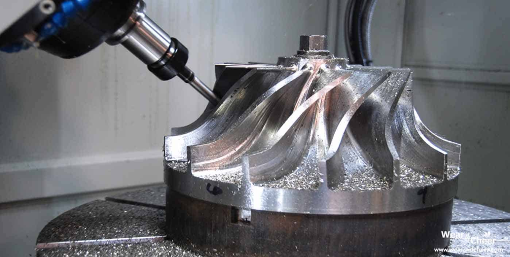
Multi-Axis CNC for Complex Parts
Five-axis and multi-axis CNC machining centers produce complex automotive components in single setups that would require multiple operations on simpler machines. Brake caliper bodies, for example, combine complex external geometry with precision-bored piston bores, fluid passages, and mounting interfaces that must all be held in accurate positional relationship to one another. A five-axis machine produces all of these features in one setup, eliminating the positional errors that accumulate when the part is repositioned between operations. [6]
Example
The mass production of brake calipers illustrates production CNC machining at its most demanding. Each caliper requires multiple precision bores, threaded ports, sealing grooves, and mounting surfaces, all held to tolerances that directly affect braking force consistency and hydraulic sealing integrity. In a production environment, caliper machining cells run at cycle times of three to five minutes per part, with in-process gauging verifying bore diameters automatically and SPC systems monitoring process capability continuously across thousands of parts per shift.
Precision, Quality Control, and Safety Standards
Precision in automotive CNC machining is not simply a manufacturing preference; it is a safety requirement. Components within braking, steering, and suspension systems operate under conditions where dimensional errors translate directly into performance failures with real consequences for vehicle occupants. Quality control in automotive CNC machining is therefore a structured, documented discipline rather than an end-of-line check.
Why Precision Is Critical in Automotive Engineering
Automotive components interact within tightly designed assemblies where every clearance, interference fit, and surface contact is engineered for a specific functional outcome. A brake caliper piston bore that is 0.05 mm oversize compromises the sealing lip contact pressure of the piston seal, risking fluid bypass under high braking loads. A steering rack that is out of position by a fraction of a millimeter affects steering geometry and introduces handling characteristics the vehicle was not designed for. At the system level, the cumulative effect of individually small dimensional errors across multiple components can produce assembly-level failures that no single part inspection would predict. [7]

CNC Machining for the Automotive Industry
Tolerance Control in CNC Machining
Automotive CNC machining operates within tolerance frameworks defined by both engineering drawings and industry standards:
- IT grades: Most automotive functional surfaces are specified to ISO tolerance grades IT6 to IT8, with safety-critical interfaces such as bearing seats and brake bores held to IT5 or tighter.
- Geometric tolerances: Position, concentricity, perpendicularity, and flatness tolerances are applied to features whose geometric relationship to other features governs assembly function. These are verified dimensionally, not just visually.
- Process capability: Automotive customers typically require CNC machining processes to demonstrate a process capability index (Cpk) of 1.33 or greater on critical characteristics, meaning the process must consistently produce parts well within the tolerance band rather than merely within it.
Inspection Methods
Automotive quality control employs a layered inspection strategy:
- Coordinate measuring machines (CMM): Three-dimensional measurement of part geometry against the nominal CAD model. CMM inspection verifies the position, form, and size of critical features to sub-micron accuracy and generates documented measurement reports for quality records.
- Laser measurement systems: Non-contact laser scanners produce full surface geometry data rapidly, enabling comparison of the machined part against the design model across the entire surface rather than at discrete measurement points.
- In-process gauging: Automated gauging integrated into the CNC machining cell measures critical dimensions during the machining cycle, allowing real-time offset correction and preventing out-of-tolerance parts from completing the cycle unnecessarily.
- Visual and tactile inspection: Surface finish verification using profilometers and visual checks for burrs, surface damage, and marking completes the inspection sequence before parts are released. [8]
Example
Brake system components represent the most demanding precision requirements in standard automotive CNC machining. Master cylinder bores are typically specified to IT6 tolerances with surface finish requirements of Ra 0.4 µm or better on the bore wall, ensuring consistent seal contact and fluid displacement characteristics across every unit produced. A single out-of-tolerance bore that passes inspection and reaches service represents an unacceptable safety risk, which is why brake component machining cells combine in-process gauging, CMM first-article inspection, and statistical process monitoring as overlapping layers of dimensional assurance.
Advantages and Limitations of CNC in the Automotive Industry
CNC machining is not the right process for every automotive component, and understanding both its strengths and its constraints is essential for making sound manufacturing decisions across a vehicle program. The clearest picture of where CNC adds value and where it does not emerges from comparing its performance across different component types and production scenarios.
Advantages
- High precision and consistency: CNC machining delivers dimensional accuracy and batch-to-batch consistency that manual and semi-automated processes cannot match at equivalent production rates. For safety-critical components, this consistency is non-negotiable.
- Fast production cycles: Modern CNC machining centers with automated tool changers, multi-pallet systems, and in-process gauging operate with minimal idle time, producing complex parts at cycle times that support high-volume automotive schedules.
- Flexibility for complex geometries: Five-axis and multi-axis CNC machines produce complex three-dimensional geometries, internal passages, and compound-angle features in single setups that would be impractical on conventional machine tools.
- Suitable for both prototyping and production: The same fundamental process serves both development and production phases, with toolpath optimization and fixture upgrading bridging the transition between them. This continuity reduces development risk by ensuring that prototype parts are manufactured by the same process as production parts.
Limitations
- High setup cost for small batches: Programming, fixturing, and prove-out costs are largely fixed per job. For very small batch sizes, these costs represent a disproportionate share of total part cost, making CNC less economical than near-net-shape processes such as casting or forging for simple high-volume parts.
- Material waste in subtractive processing: CNC machining removes material from solid stock, generating chips that represent wasted raw material. For expensive materials such as titanium, material utilization ratios can be low, adding high cost per part compared to near-net-shape alternatives.
- Not always ideal for extremely high-volume low-cost parts: Simple components produced in millions of units per year, such as standard fasteners, sheet metal brackets, and injection-molded interior trim, are more economically produced by stamping, casting, or molding than by CNC machining, which cannot match the unit economics of these processes at extreme volumes.
Example
A useful comparison is between CNC-machined performance car components and mass-stamped economy car parts. A performance vehicle brake caliper is CNC machined from a billet aluminum forging, producing a component with optimized geometry, minimum weight, and maximum stiffness at a unit cost that is justified by the vehicle's performance and price positioning. An equivalent function on an economy vehicle uses a cast iron caliper produced by casting and minimal finish machining, prioritizing low unit cost over weight and geometric complexity. Neither approach is wrong; each is correctly matched to the production volume, cost target, and performance requirement of its application.
Conclusion
CNC machining supports the automotive industry across its full development and production lifecycle, from early prototype validation through to high-volume serial production. Its precision, repeatability, and flexibility across materials and geometries make it the preferred process for components where dimensional accuracy directly affects vehicle safety, performance, and reliability.
As vehicles grow more complex with electrification and lightweighting demands, CNC machining continues to evolve alongside them. The process that validates a design in prototype form is the same one that scales to produce millions of units with consistent quality, making it not just relevant but indispensable to modern automotive manufacturing.
References
Ali. (2017). State-of-the-Art of CMM-Coordinate Metrology in Automotive Industry. SAE Technical Papers on CD-ROM/SAE Technical Paper Series. https://doi.org/10.4271/2017-01-0397
Alsoufi, M. S., Bawazeer, S. A., Alhazmi, M. W., Hijji, H. H., Alhazmi, H., & Alqurashi, H. F. (2025). Dimensional Accuracy and Measurement Variability in CNC-Turned Parts Using Digital Vernier Calipers and Coordinate Measuring Machines Across Five Materials. Materials, 18(12), 2728. https://doi.org/10.3390/ma18122728
Bibi, S., & Sajid, M. (2025). Towards Cost Modelling for Rapid Prototyping and Tooling Technology-Based Investment Casting Process for Development of Low-Cost Dies. MTME 2025, 6. https://doi.org/10.3390/materproc2025023006
Creative Uses of CNC Machining in the Automobile Industry. (2025). Jlccnc.com. https://jlccnc.com/blog/cnc-applications-automotive
Li, S., Yue, X., Li, Q., Peng, H., Dong, B., Liu, T., Yang, H., Fan, J., Shu, S., Qiu, F., & Jiang, Q. (2023). Development and applications of aluminum alloys for the aerospace industry. Journal of Materials Research and Technology, 27, 944–983. https://doi.org/10.1016/j.jmrt.2023.09.274
Medina, S., Acuña-Rivera, M., Castellanos, S., & Castro, K. (2025). Evaluation of Machining Parameters in Turning Al7075-T6 Aluminum Alloy Using Dry, Flooded, and Cryogenic Cutting Fluid Conditions. Journal of Manufacturing and Materials Processing, 9(10), 328. https://doi.org/10.3390/jmmp9100328
Tyflopoulos, E., Lien, M., & Steinert, M. (2021). Optimization of Brake Calipers Using Topology Optimization for Additive Manufacturing. Applied Sciences, 11(4), 1437. https://doi.org/10.3390/app11041437
Zhou, L., Miller, J., Vezza, J., Mayster, M., Raffay, M., Justice, Q., Al Tamimi, Z., Hansotte, G., Sunkara, L. D., & Bernat, J. (2024). Additive Manufacturing: A Comprehensive Review. Sensors, 24(9), 2668. https://doi.org/10.3390/s24092668