Tighter CNC machining tolerance does not automatically mean a better part. In precision manufacturing, the best tolerance is the one that protects function without adding unnecessary cost, inspection burden, scrap risk, or machining difficulty.
Many engineers and buyers request tight tolerances because they associate them with higher quality. That assumption can create real production problems. A feature may be held to ±0.01 mm even though the part would work properly at ±0.10 mm. The result is slower machining, higher inspection costs, longer lead times, and a greater chance of rejection.
The central engineering question is not “How tight can the machine hold?” The real question is “What functional failure occurs if this tolerance is relaxed?”
For CNC-machined parts, tolerance decisions affect tooling, setup strategy, material selection, inspection method, supplier capability, and assembly performance. This is why tolerance planning should happen before quoting and before production begins.
Why Over-Toleranced Drawings Create Manufacturing Problems
Over-toleranced drawings create manufacturing problems because they force suppliers to control dimensions more tightly than the product function requires. This increases machining time, inspection effort, and scrap risk without improving performance.
A CNC machine may be capable of high precision, but that does not mean every surface should receive a tight tolerance. A bearing bore, dowel hole, sealing face, or sliding interface may need tight control. A cosmetic edge, clearance cut, or outside profile often does not.
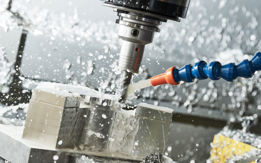
When unnecessary tolerances are added to non-critical features, the shop may need extra finishing passes, slower cutting parameters, additional tool changes, more inspection points, and tighter process control. These steps increase cost even when the part does not become functionally better.
Engineers should review assembly drawings, functional requirements, historical tolerance stack reports, and production scrap records before assigning tight tolerances. If a dimension does not affect fit, motion, sealing, alignment, or safety, it may not need tight control.[3]
Engineering Records To Review
| Record | What It Reveals |
| Assembly Drawings | Which features actually control fit and alignment |
| Functional Requirement Documents | What failure the tolerance is meant to prevent |
| Tolerance Stack Reports | How multiple dimensions combine in assembly |
| Production Scrap Reports | Which tolerances cause repeated rejection |
| Customer Nonconformance Reports | Which features create real field or assembly issues |
Why Tight Tolerances Fail During Production, Even When The Machine Is Capable
Tight tolerances fail during production when the drawing assumes machine accuracy is the same as production capability. They are not the same.
A machine may hit a dimension once during a controlled setup. Production requires repeatability across multiple parts, tools, operators, material lots, fixtures, and inspection cycles. Tool wear, fixture repeatability, thermal growth, and material movement all affect final results.
Prototype success can also be misleading. A prototype may pass because one machinist carefully controls every step. A production run may fail because the same tolerance must be repeated hundreds or thousands of times under real cycle-time and inspection conditions.
This is why tight tolerance should be supported by process capability data, not only by machine specifications. Cp and Cpk studies, first article inspections, tool wear reports, and production capability records help determine whether a tolerance can be held reliably.
Manufacturing Data To Review
| Manufacturing Data | Why It Matters |
| Cp / Cpk Studies | Shows whether the process is statistically capable |
| First Article Inspection | Confirms the first production part meets requirements |
| Tool Wear Reports | Shows whether dimensions drift during production |
| Fixture Repeatability Data | Confirms the part locates consistently |
| Batch Inspection History | Shows whether tolerance can be held across lots |
How Material Behavior Changes Tolerance Capability
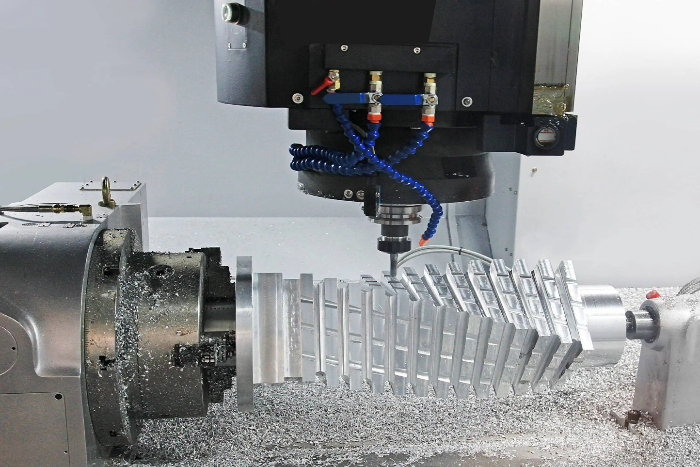
Material behavior changes tolerance capability because every material reacts differently to cutting force, heat, residual stress, and measurement conditions. Tolerance is not only a machine issue. It is also a material stability issue.
Section: How Material Behavior Changes Tolerance Capability
Aluminum is often easy to machine, but thin aluminum components can distort after heavy material removal. Residual stress may release during roughing and change flatness after the part is unclamped. Large pockets and thin ribs increase this risk.
Stainless steel creates higher cutting forces and more heat than aluminum. This can affect dimensional control, tool wear, burr formation, and surface finish. Tight tolerances in stainless steel often require slower machining and stronger process control.
Titanium retains heat near the cutting zone and can accelerate tool wear. Tight tolerance titanium machining usually needs conservative cutting parameters, rigid setup, and careful inspection.
Engineering plastics create another challenge. Plastics may expand from heat, absorb moisture, deform under clamping pressure, or move after machining. A plastic part may measure correctly immediately after cutting but change after cooling or environmental exposure.
Material Behavior
| Material Group | Tolerance Risk | Why It Happens | Manufacturing Response |
| Aluminum | Thin-wall distortion | Residual stress and material removal | Balanced roughing and finishing |
| Stainless Steel | Heat and cutting force | Harder cutting and tool wear | Rigid setup and controlled feeds |
| Titanium | Thermal concentration | Low thermal conductivity | Conservative parameters and sharp tools |
| Brass | Burrs and small feature control | Free cutting but edge-sensitive | Deburring and inspection planning |
| Plastics | Expansion and movement | Heat, moisture, and clamping stress | Low-stress fixturing and stabilization |
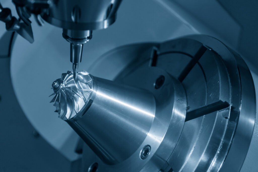
Which Features Actually Require Tight Tolerances?
Tight tolerances are required only when the part function depends on precise geometry. These features usually include bearing bores, precision locating holes, sealing surfaces, datum features, and sliding interfaces.
A bearing bore needs tight size, roundness, and alignment because poor control can cause noise, wear, heat, or seizure. A sealing surface may need flatness and finish control to prevent leakage. A locating hole may need positional tolerance because it controls how the assembly fits together.
By contrast, cosmetic edges, clearance cuts, outside profiles, and non-functional surfaces often do not need tight tolerance. Holding these features too tightly increases cost without improving assembly or service life.
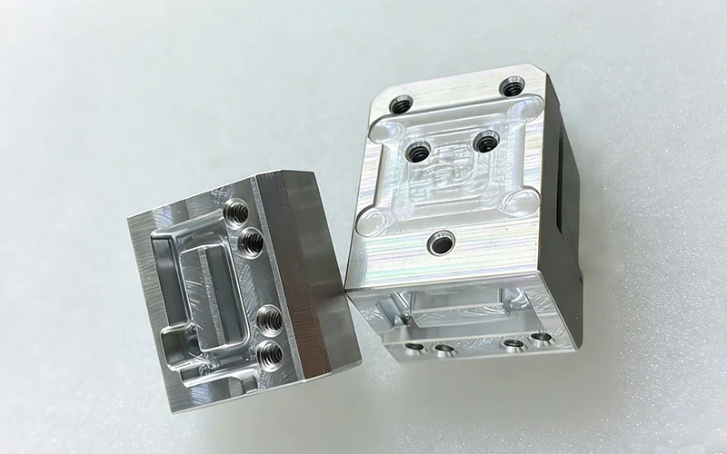
Real Example: Precision Bearing Housing vs External Mounting Plate
A precision bearing housing may require a tight bore tolerance, controlled roundness, and clear datum references. If the bore is too large, the bearing may slip. If it is too small, installation may damage the part.
An external mounting plate is different. If its outer edge is not function-critical, holding it to the same tolerance as the bearing bore adds unnecessary cost. The correct approach is to apply a tight tolerance to the bearing interface and a standard tolerance to non-functional geometry.
Tolerance Stack-Up: The Failure Engineers Discover Too Late
Tolerance stack-up causes assembly failure when individually acceptable dimensions combine into an unacceptable total variation. A part can pass inspection and still fail in assembly if the complete system was not analyzed.
This is common in CNC-machined assemblies with multiple holes, mating plates, spacers, covers, brackets, and locating features. Each dimension may be within tolerance, but the combined variation may shift the final position beyond what the assembly allows.
Linear tolerance stack-up occurs when dimensions accumulate in one direction. Geometric stack-up is more complex because it includes position, orientation, flatness, perpendicularity, and datum relationships.
Engineers should review assembly models, GD&T studies, stack-up reports, and functional fit simulations before tightening individual dimensions. The goal is not to make every part tighter. The goal is to control the features that drive assembly function.
Standard Tolerances vs Medium Tolerances vs Tight Tolerances
Standard, medium, and tight tolerances should be selected according to functional risk. Standard tolerance fits general features. Medium tolerance fits assembly-relevant features. Tight tolerance fits critical features where function depends on precision.
Standard tolerances are often suitable for general profiles, non-critical surfaces, clearance features, and parts with forgiving assembly requirements. They support cost efficiency and faster production.
Medium tolerances are used when repeatable assembly matters, but the feature does not require extreme precision. Examples include mounting holes, enclosure interfaces, and general mating surfaces.
Tight tolerances are reserved for features where mechanical performance depends on precision. These include bearing fits, sealing areas, sliding components, precision bores, and alignment-critical datums. [1][6]
Typical Use
| Feature Type | Recommended Tolerance Strategy |
| Cosmetic outside profile | Standard |
| Clearance slot | Standard or medium |
| Mounting hole pattern | Medium |
| Dowel hole | Tight |
| Bearing bore | Tight |
| Sealing face | Tight with surface finish control |
| General pocket depth | Standard or medium |
| Sliding interface | Tight where motion depends on fit |
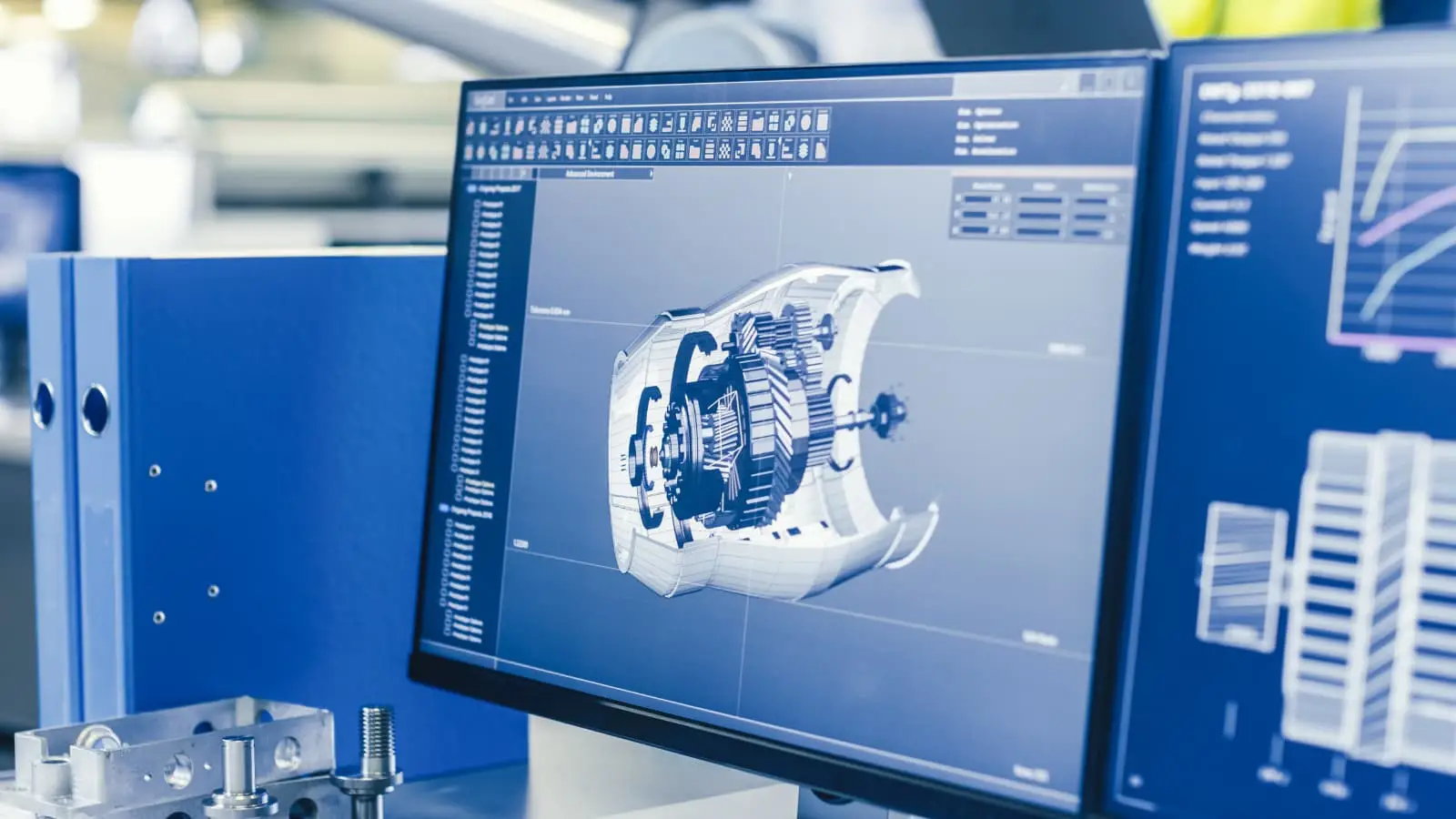
Why GD&T Often Solves Problems Better Than Tighter Dimensions
GD&T often solves tolerance problems better than tighter plus/minus dimensions because it controls how features relate to functional datums. A tighter dimension does not always describe how the part should assemble or be inspected.
For example, a hole pattern can be dimensioned with separate X and Y plus/minus values. This may create confusion about inspection, functional fit, and allowable variation. A positional tolerance tied to datums often communicates the functional requirement more clearly.
GD&T can control position, flatness, perpendicularity, profile, runout, and orientation. These controls are useful when the relationship between features matters more than a single size dimension.[2] [4]
Real Example: Hole Location Control
A machined plate may include four mounting holes that must align with another component. If each hole is controlled only by coordinate dimensions, the supplier and buyer may inspect the part differently.
Using positional tolerance relative to datums can define the acceptable hole location more clearly. This reduces inspection disputes and better reflects the assembly function.[5]
GD&T should not be used to make every feature tighter. It should be used to communicate which relationships actually control the function.
Inspection Challenges When Tolerances Become Extremely Tight
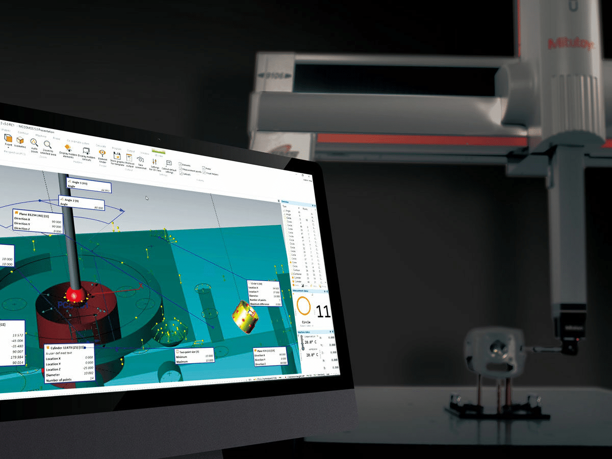
Extremely tight tolerances create inspection challenges because measurement uncertainty becomes significant. A part may appear good or bad depending on equipment capability, temperature, fixturing, probe force, and inspection method.
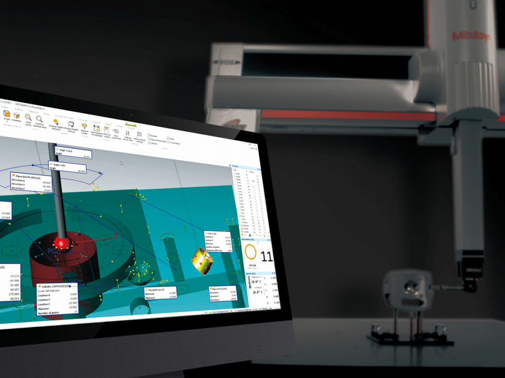
Source: Mitutoyo CMM Programming Solutions
CMM inspection is powerful, but it still requires correct datum setup, calibrated equipment, trained operators, and a suitable measurement strategy. Gauge inspection can be faster, but it must match the feature and tolerance being checked.
Temperature also matters. Metals expand and contract with temperature changes. Plastics can move even more. A dimension measured immediately after machining may not match the same dimension after cooling.
Quality teams should review CMM reports, gauge R&R studies, calibration records, and inspection procedures before accepting extremely tight tolerances. If measurement uncertainty is too large relative to the tolerance, the inspection result may be unreliable.[7]
Process Table: From Drawing To Inspection Approval
| Step | Engineering Question | Manufacturing Risk | Quality Control Action |
| Drawing Review | Which features control function? | Over-tolerancing | Separate critical and non-critical features |
| Process Planning | Can the process hold the tolerance repeatedly? | Prototype success but production failure | Review capability and setup plan |
| Machining | Will tool wear or heat shift dimensions? | Dimensional drift | Monitor tool life and thermal stability |
| Inspection | Can the feature be measured reliably? | Measurement uncertainty | Use CMM, gauges, or optical systems correctly |
| Final Approval | Does the part function in assembly? | Passing dimensions but failed fit | Verify mating fit and datum relationships |
Industry Examples Where Tolerance Decisions Drive Product Success
Tolerance decisions affect each industry differently. Aerospace, medical, automotive, electronics, and industrial manufacturing all need precision, but not every feature needs the same level of control.
Source: BaiChuan Precision CNC Milling Service
Aerospace Components
Aerospace parts may require tight tolerance on critical interfaces, fastener holes, actuator features, and datum surfaces. However, non-functional geometry should not automatically receive the same tolerance.
A lightweight aerospace bracket may need controlled hole position and flatness at mounting interfaces. External contour surfaces may allow more relaxed tolerance if they do not affect assembly or load path.
Medical Device Components
Medical device components often require tight control for fit, repeatable motion, cleanability, and safety. Surgical tools, diagnostic equipment parts, and precision fixtures may require careful tolerance planning.
However, even in medical parts, over-tolerancing non-functional surfaces can increase cost unnecessarily. Functional surfaces, mating components, and inspection-critical features should receive the highest control.
Automotive Components
Automotive production often balances tolerance with volume and cost. Brackets, housings, transmission components, and EV battery tray parts need repeatable assembly, but production cost matters.
A high-volume automotive mounting bracket may need medium tolerance on hole patterns and flatness at mating surfaces. Cosmetic or clearance features may use standard tolerance to control production cost.
Electronics Housings
Electronics housings require tolerance control where connectors, boards, buttons, camera modules, and heat sinks align. Connector openings and PCB mounting features often matter more than outer cosmetic geometry.
Heat sink surfaces may need flatness and surface finish control for thermal contact. Non-functional enclosure edges can often use standard tolerance.
Industrial Equipment
Industrial equipment parts include tooling plates, bearing mounts, robotic grippers, valve blocks, and fixtures. These parts often require tight tolerance on bearing fits, dowel holes, sealing surfaces, and datum faces.
General exterior surfaces, clearance holes, and non-critical pockets may use standard or medium tolerance. The best result comes from separating functional features from general geometry.
Common Tolerance Mistakes Engineers, Buyers, And Manufacturers Repeat
The most common tolerance mistake is applying aerospace-level tolerances to industrial parts. This often happens because teams want a “high-quality” drawing, but it creates cost and inspection problems.
Another mistake is using tolerance to compensate for weak design. If a part does not locate properly, tightening every dimension may not solve the root problem. Better datum structure or locating features may be needed.
Material movement is also frequently ignored. Thin-wall parts, large pockets, plastics, and stress-relieved materials behave differently after machining. A tolerance that looks reasonable on paper may be difficult after material removal.
Inspection planning is often added too late. If a drawing requires tight GD&T but the supplier cannot measure it properly, production approval becomes difficult.
Decision Framework: How Tight Should Your CNC Machining Tolerance Be?
Tolerance should be selected based on function, production capability, inspection capability, and failure risk. The loosest tolerance that protects function is usually the best engineering choice. [8]
Use Standard Tolerances When:
- Function does not depend on precision fit
- Cost efficiency is important
- Assembly requirements are forgiving
- Features are cosmetic or non-critical
- Clearance is generous
Use Medium Tolerances When:
- Assembly repeatability matters
- Mating components require consistency
- Hole patterns affect fit
- Enclosure interfaces need controlled alignment
- Production volume requires repeatability
Use Tight Tolerances When:
- Mechanical performance depends on precision
- Bearing fits are involved
- Sealing surfaces must be controlled
- Motion or sliding fit is critical
- Datum features control assembly
- Engineering analysis supports the requirement
The best tolerance is not the tightest tolerance. It is the tolerance that protects function with the least manufacturing risk.
Frequently Asked Questions
What Is A Standard CNC Machining Tolerance?
A standard CNC machining tolerance is a general allowable variation used for non-critical features. It is suitable when the feature does not control fit, motion, sealing, or alignment.
When Is A Tight Tolerance Necessary?
A tight tolerance is necessary when part's function depends on precise control. Common examples include bearing bores, dowel holes, sealing faces, sliding interfaces, and datum features.
How Do Tolerances Affect Machining Cost?
Tighter tolerances increase machining cost because they often require slower cutting, more finishing passes, better fixturing, more inspection, and higher scrap risk.
Why Do Parts Fail Despite Passing Inspection?
Parts can fail despite passing inspection because individual dimensions may be within tolerance while the full assembly stack-up fails. Poor datum strategy can also cause measurement and assembly differences.
What Causes Tolerance Stack-Up Problems?
Tolerance stack-up problems occur when multiple acceptable variations combine into a larger assembly error. This often happens when designers review dimensions individually instead of analyzing the full assembly.
Should Every Critical Feature Use GD&T?
Not every feature needs GD&T, but features controlled by position, orientation, flatness, profile, or datum relationships often benefit from it. GD&T should clarify function, not add complexity.
How Are Tight Tolerances Inspected?
Tight tolerances may be inspected with CMMs, precision gauges, optical systems, surface roughness testers, or dedicated fixtures. The method depends on feature type and required accuracy.
What Tolerance Should I Specify On A CNC Drawing?
Specify the loosest tolerance that still protects function. Use standard tolerances for non-critical features, medium tolerances for assembly features, and tight tolerances only where failure risk justifies them.
The Best Tolerance Is The One That Protects Function Without Creating Unnecessary Risk
The best CNC machining tolerance is not the smallest number on the drawing. It is the tolerance that allows the part to function correctly while staying manufacturable, measurable, repeatable, and cost-effective.
Over-tolerancing creates hidden risk. It increases cycle time, inspection effort, supplier cost, scrap rate, and measurement disputes. It can also distract from the features that truly matter.
Successful CNC projects balance performance, cost, repeatability, material behavior, and inspection capability. Standard, medium, and tight tolerances all have a place, but each should be used for the right reason.
Tighter tolerance should be treated as an engineering decision, not a quality badge.
References
1. International Organization for Standardization. ISO 2768-1:1989, General Tolerances. ISO.
https://www.iso.org/obp/ui/en/
2. ASME. ASME Y14.5, Dimensioning and Tolerancing. ASME.
https://www.asme.org/codes-standards/find-codes-standards/y14-5-dimensioning-tolerancing
3. Swyt, D. A. (1992). Challenges to NIST in dimensional metrology: The impact of tightening tolerances in the U.S. discrete-part manufacturing industry. NISTIR 4757. National Institute of Standards and Technology.
https://nvlpubs.nist.gov/nistpubs/Legacy/IR/nistir4757.pdf
4. Salsbury, D. (2019). GD&T and the new ASME Y14.5-2018. Mitutoyo America.
https://www.mitutoyo.com/webfoo/wp-content/uploads/ASME_Y14.5-2018_Salsbury.pdf
5. ASME. Geometric Dimensioning and Tolerancing Collection. ASME Learning and Development.
https://www.asme.org/learning-development/learning-experiences/geometric-dimensioning-and-tolerancing-collection
6. ZEISS Quality Forum. ISO 2768 General Tolerances Chart. ZEISS Quality Forum.
https://qualityforum.zeiss.com/migration/images/137_8bb2b6eeb6a9e6554d254c216a890c89.pdf
7. Swyt, D. A. (1993). A report of a NIST industry-needs workshop. National Institute of Standards and Technology.
https://pmc.ncbi.nlm.nih.gov/articles/PMC4909183/
8. Fictiv. (2022). ISO 2768: An international standard for CNC machining tolerances. Fictiv Engineering.
https://www.fictiv.com/articles/iso-2768-an-international-standard