


Most CNC machining problems are not created on the machine. They are designed into the part before cutting begins. Deep pockets, sharp internal corners, thin walls, unclear datums, unnecessarily tight tolerances, and difficult inspection requirements can make a part expensive before the CNC programmer even starts toolpath planning.
Design for Manufacturability, or DFM, is the process of reviewing a part so it can be machined efficiently, inspected reliably, and assembled successfully without sacrificing the product’s real function. For CNC-machined parts, DFM connects geometry, material selection, tolerance strategy, setup planning, tool access, and quality control.
Good DFM does not mean simplifying the part until it loses function. It means protecting the function while removing avoidable manufacturing risk.
The central engineering question is simple: Does every feature justify the cost, setup time, inspection burden, or production risk it creates? [1]
Which Design Decisions Create The Most CNC Manufacturing Risk?
The highest CNC manufacturing risk usually comes from geometry that looks acceptable in CAD but creates unstable machining conditions in production. Deep pockets, thin walls, sharp internal corners, difficult-to-reach features, and multi-direction machining requirements are common examples.
A CAD model can show a perfect square corner, but CNC cutting tools are round. A CAD model can show a deep cavity, but the machine may need a long tool that deflects. A CAD model can show a thin wall, but that wall may chatter, bend, or distort during machining.
The risk increases when these features are combined with tight tolerances. A deep pocket with a tight wall tolerance is more difficult than a shallow pocket with general tolerance. A thin aluminum wall may be possible, but not if it must also hold extreme flatness after heavy material removal.
Engineers should review CAD models, design revision history, functional feature analysis, and machining feasibility reports before releasing drawings. The goal is to identify which features affect function and which only add manufacturing difficulty.
Engineering Records To Review
| Engineering Record | What It Helps Identify |
| CAD Model | Tool access, wall thickness, pocket depth, sharp corners |
| Design Revision History | Features added without manufacturability review |
| Functional Feature Analysis | Which geometry actually affects performance |
| Machining Feasibility Review | Set up count, tool reach, fixture risk |
| Supplier DFM Feedback | Costly or unstable manufacturing features |
Why Parts Become Expensive Before Programming Begins
Parts become expensive before programming begins when the design requires extra setups, special tooling, slow machining, complex fixtures, or difficult inspection. These costs are often hidden during early design review.
Source: CNC Enclosure Design for Machining
A part with features on five different faces may require several setups. Each setup requires fixturing, alignment, toolpath planning, and inspection. If critical features depend on relationships across those setups, the risk increases further.
Special tooling also adds cost. Very small internal radii, deep holes, narrow slots, and long-reach pockets may require nonstandard cutters. These tools may be slower, weaker, and more expensive than standard tools.
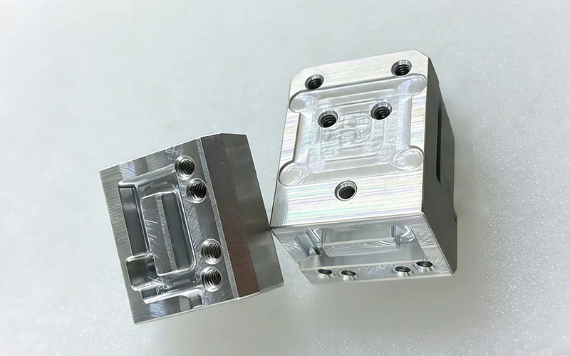
Real Example: Lightweight Aluminum Housing With Deep Cavities
A lightweight aluminum electronics housing may include deep pockets to reduce weight. The design may look efficient, but the deep cavities can require long tools, slow step-downs, extra finishing passes, and careful inspection.
If the housing also has thin walls, the problem becomes harder. Material removal can release stress and cause distortion. The design can often be improved by increasing internal radii, reducing pocket depth, or separating critical surfaces from weight-reduction geometry.
How Material Selection Changes Manufacturability
Material selection changes manufacturability because each material responds differently to cutting heat, tool pressure, clamping, residual stress, and finishing. DFM should review material behavior before tolerance and geometry are finalized.
Aluminum is commonly used for CNC-machined parts because it machines efficiently and supports high-speed cutting. However, thin aluminum walls and large pockets can distort after material removal, especially when residual stress is released.
Stainless steel offers strength and corrosion resistance, but it creates more heat and tool wear than aluminum. Tight features in stainless steel may need slower cutting, stronger workholding, and more careful burr control.
Titanium is valuable for aerospace and medical applications, but it is difficult to machine. It retains heat near the cutting zone, wears tools quickly, and requires conservative cutting parameters.
Engineering plastics add another challenge. Plastics can deform under clamping pressure, expand with heat, absorb moisture, or move after machining. For plastic parts, low-stress fixturing and stabilization are often more important than aggressive cycle-time reduction.
Material Manufacturability Table
| Material | DFM Risk | Why It Happens | Better Design Response |
| Aluminum | Thin-wall distortion | Residual stress and material removal | Add support, avoid extreme wall reduction |
| Stainless Steel | Tool wear and burrs | Higher cutting force and heat | Simplify small features, plan deburring |
| Titanium | Heat concentration | Low thermal conductivity | Avoid unnecessary tight features |
| Brass | Burrs on small edges | Free cutting but edge-sensitive | Add edge breaks and inspection notes |
| Engineering Plastics | Deformation and movement | Heat, moisture, and clamping stress | Use low-stress fixturing and realistic tolerance |
Why Tool Access Controls CNC Design Success
Tool access controls CNC design success because every machined feature must be reached by a real cutting tool. If the cutter cannot reach the feature rigidly, the part may require extra setups, special tools, EDM, or redesign.
Source: Hubs CNC Machining Design Guide
Internal corner radius is one of the most common DFM issues. Since milling tools are round, internal corners cannot be perfectly sharp. A larger radius allows a larger cutter, which improves rigidity, lowers cycle time, and improves surface quality.
Deep cavity machining creates another access problem. The deeper and narrower the pocket, the longer the tool must be. Long tools deflect more easily and can create tapered walls, chatter, poor finish, and tolerance failure.
Hole accessibility also matters. Angled holes, cross holes, and blind holes may require special setups. If the hole is deep and small, drill wandering, chip packing, and broken tools become more likely. [2]
Manufacturing Data To Review
| Manufacturing Data | Why It Matters |
| Tool Library Availability | Confirms whether standard cutters can make the feature |
| Tool Reach Requirements | Identifies deflection and chatter risk |
| Cycle-Time Estimate | Shows cost impact of difficult geometry |
| Machine Capability Report | Confirms axis access and travel limits |
| Fixture Strategy | Shows whether the part can be held safely |
What Causes Thin-Wall Parts To Fail During Machining?
Thin-wall parts fail during machining because cutting force, heat, vibration, and residual stress can move the material while it is being cut. A thin wall may pass in CAD but fail in production because it lacks stiffness.
During milling, a cutter pushes against the wall. If the wall is too thin, it can flex away from the tool and spring back after cutting. This creates dimensional error and poor surface finish.
Chatter leaves visible tool marks, reduces surface quality, and may require slower machining. In some cases, the part must be redesigned with thicker walls, ribs, or improved support. [3]
Real Example: Aerospace Bracket With Aggressive Weight-Reduction Pockets
Aerospace brackets often use pockets to reduce weight. This is useful when weight reduction has measurable value, but aggressive pocketing can create thin ribs and unstable walls.
Source: RapidDirect CNC Machining Design Guide
The design may need staged roughing and finishing. Engineers may also increase corner radii, adjust wall thickness, or move from a simple 3-axis plan to multi-axis machining to improve support and tool access.
Why Over-Tolerancing Creates More Problems Than It Solves
Over-tolerancing creates more problems than it solves because it forces the manufacturer to hold dimensions tighter than the function requires. This increases cost, inspection effort, and scrap risk.
Not every feature needs precision tolerance. A bearing bore, dowel hole, sealing face, or sliding interface may need tight control. A cosmetic surface, clearance pocket, or non-functional outside profile usually does not.
When tight tolerances are applied everywhere, manufacturing becomes slower and more expensive. The supplier may need more finishing passes, better fixtures, special inspection, and stricter process control. [5]
Tight tolerance should be used where failure risk justifies it, not as a general quality signal.
Tolerance Strategy Table
| Feature Type | DFM Recommendation | Reason |
| Bearing bore | Tight tolerance | Controls fit, rotation, and service life |
| Dowel hole | Tight positional control | Controls assembly alignment |
| Sealing surface | Tight flatness and finish | Prevents leakage |
| Cosmetic edge | Standard tolerance | Usually does not affect function |
| Clearance cut | Standard or medium tolerance | Allows assembly clearance |
| General pocket | Standard or medium tolerance | Avoids unnecessary inspection cost |
How Poor Datum Strategy Creates Manufacturing And Inspection Failures
Poor datum strategy creates manufacturing and inspection failures because the supplier and customer may not measure the part from the same references. A part can pass one inspection method and fail another. [6]
Datums define how the part is located, machined, and measured. If the drawing does not clearly define the datum hierarchy, critical features may be inspected from the wrong surfaces.
This is especially important for multi-setup CNC parts. If a part is flipped or moved between operations, datum transfer must be controlled. Otherwise, holes, pockets, slots, and mating faces may drift relative to each other.
GD&T can help when feature relationships control the function. Position, flatness, perpendicularity, profile, and runout callouts can communicate design intent more clearly than unrelated plus/minus dimensions. [4]
Designing Holes, Threads, And Internal Features For Efficient Machining
Holes, threads, and internal features should be designed around tool access, realistic depth, chip evacuation, and inspection. Small changes in depth or thread requirement can significantly affect machining cost.
Deep holes increase drill wander and chip evacuation problems. Blind holes can trap chips and reduce thread quality. Very small holes may require fragile tools and slower machining.
Thread depth should be based on functional engagement, not habit. Excessive thread depth increases tapping time and tool breakage risk without improving performance in many applications.
Cross holes can also create burrs inside the part. If a cross hole intersects a bore or fluid passage, deburring and inspection become important. Designers should consider whether the feature can be accessed and cleaned after machining.
How to Set Up Count Drives: Cost, Accuracy, And Lead Time
Setup count drives cost, accuracy, and lead time because every setup adds alignment, fixturing, toolpath, and inspection risk. A part that can be machined in one setup is usually more stable than a part that requires several repositions.
Each time a part is moved, the manufacturer must reestablish its location. This can create positional variation between features. If the part has tight relationships between faces, holes, and datums, the setup count becomes a major quality issue.
Setup reduction does not always require a simpler part. Sometimes it requires better feature orientation, improved datum planning, or the use of 4-axis or 5-axis machining.
Process Table: DFM Impact Of Setup Count
| Setup Condition | Manufacturing Impact | DFM Improvement |
| One setup | Better datum control and shorter lead time | Align features with tool access |
| Two setups | Moderate datum transfer risk | Define clear primary and secondary datums |
| Three or more setups | Higher cost and inspection complexity | Redesign feature orientation or use multi-axis machining |
| Hard-to-fixture geometry | Higher clamping and distortion risk | Add stable locating surfaces |
| Critical features across setups | Higher positional risk | Use GD&T and process planning early |
Real Example: Industrial Valve Body Requiring Multiple Orientations
An industrial valve body may require ports, threaded holes, sealing faces, and internal passages on several sides. If each side needs a separate setup, the cost and inspection complexity increase.
DFM can improve the design by aligning ports where possible, adding inspection-friendly datums, simplifying non-critical faces, and planning the setup sequence before production.
Industry Examples Where DFM Directly Affects Production Success
DFM affects production success across automotive, aerospace, medical, electronics, and industrial manufacturing because each industry has different functional risks.

Source: Medical Parts Precision Machining
Automotive components such as battery tray brackets, suspension supports, sensor brackets, and thermal plates often require repeatable assembly. DFM focuses on hole patterns, flatness, weight reduction, and production cost.
Aerospace components often need lightweight geometry, controlled datums, and reliable inspection. DFM must balance weight-reduction pockets with stiffness, tool access, and certification requirements.
Medical device components need burr control, clean surface finish, material traceability, and inspection reliability. Surgical instruments, diagnostic housings, and precision fixtures must be designed for both machining and cleaning.
Electronics components such as heat sinks, connector plates, RF housings, and sensor enclosures require flatness, thermal contact, and cosmetic finishing. DFM helps separate functional surfaces from non-critical external geometry.
Industrial equipment parts such as tooling plates, manifolds, robotic grippers, and valve blocks often require accurate holes, sealing faces, and durable threads. DFM reduces setup count, improves inspection, and prevents avoidable rework.
Common DFM Mistakes Engineers Repeat
The most common DFM mistake is designing around ideal geometry instead of tool access. CAD allows perfect sharp corners, deep pockets, and thin walls, but CNC machining requires real tools, real fixtures, and measurable features.
Another repeated mistake is using tight tolerance as a quality signal. This increases cost but may not improve function. A better approach is to control only the features that affect fit, sealing, alignment, or motion.
Engineers also ignore inspection requirements. A feature may be machineable but difficult to verify. If the part cannot be measured reliably, production approval becomes difficult.
Material behavior is also overlooked. Stronger material is not always easier to machine. A high-strength material may increase tool wear, heat, distortion, and cycle time.
DFM Review Checklist Before Releasing A CNC Drawing
A CNC drawing should be reviewed for geometry, material, tolerance, datums, inspection, setup count, surface finish, and manufacturing risk before release.
DFM Checklist
| Review Area | Question To Ask |
| Geometry Review | Can standard tools reach all features? |
| Material Review | Does the material match function and machinability? |
| Tolerance Review | Are tight tolerances limited to critical features? |
| Datum Review | Are functional references clearly defined? |
| Inspection Review | Can critical features be measured reliably? |
| Setup Review | Can setup count be reduced? |
| Surface Finish Review | Are finish requirements function-based? |
| Risk Review | Which features drive cost, scrap, or delay? |
This checklist should be used before supplier quoting. Early DFM review reduces redesign, production delays, and avoidable costs. [7]
Frequently Asked Questions
What Is The Biggest DFM Mistake In CNC Machining?
The biggest DFM mistake is designing features that look simple in CAD but require difficult tool access, tight tolerances, extra setups, or special inspection in production.
How Do Deep Pockets Affect Machining Cost?
Deep pockets require long tools, slower cutting, more step-downs, and careful finishing. They increase tool deflection, cycle time, chatter risk, and inspection difficulty.
Why Are Sharp Internal Corners A Problem?
Sharp internal corners are difficult because milling tools are round. A sharp corner may require a very small cutter, EDM, or redesign with a practical internal radius.
When Should GD&T Be Used In CNC Design?
GD&T should be used when feature relationships control the function. It is useful for position, flatness, perpendicularity, profile, and datum-based inspection.
How Do Thin Walls Affect Part Quality?
Thin walls can flex, chatter, distort, or move after machining. They may require slower machining, better fixture support, or design changes.
What Features Increase Setup Count?
Features on multiple faces, angled holes, cross holes, undercuts, and hard-to-reach surfaces often increase setup count. More setups increase cost and datum-transfer risk.
How Does Material Selection Affect Manufacturability?
Material affects tool wear, heat, distortion, burr formation, surface finish, and inspection. Aluminum, stainless steel, titanium, brass, and plastics all require different strategies.
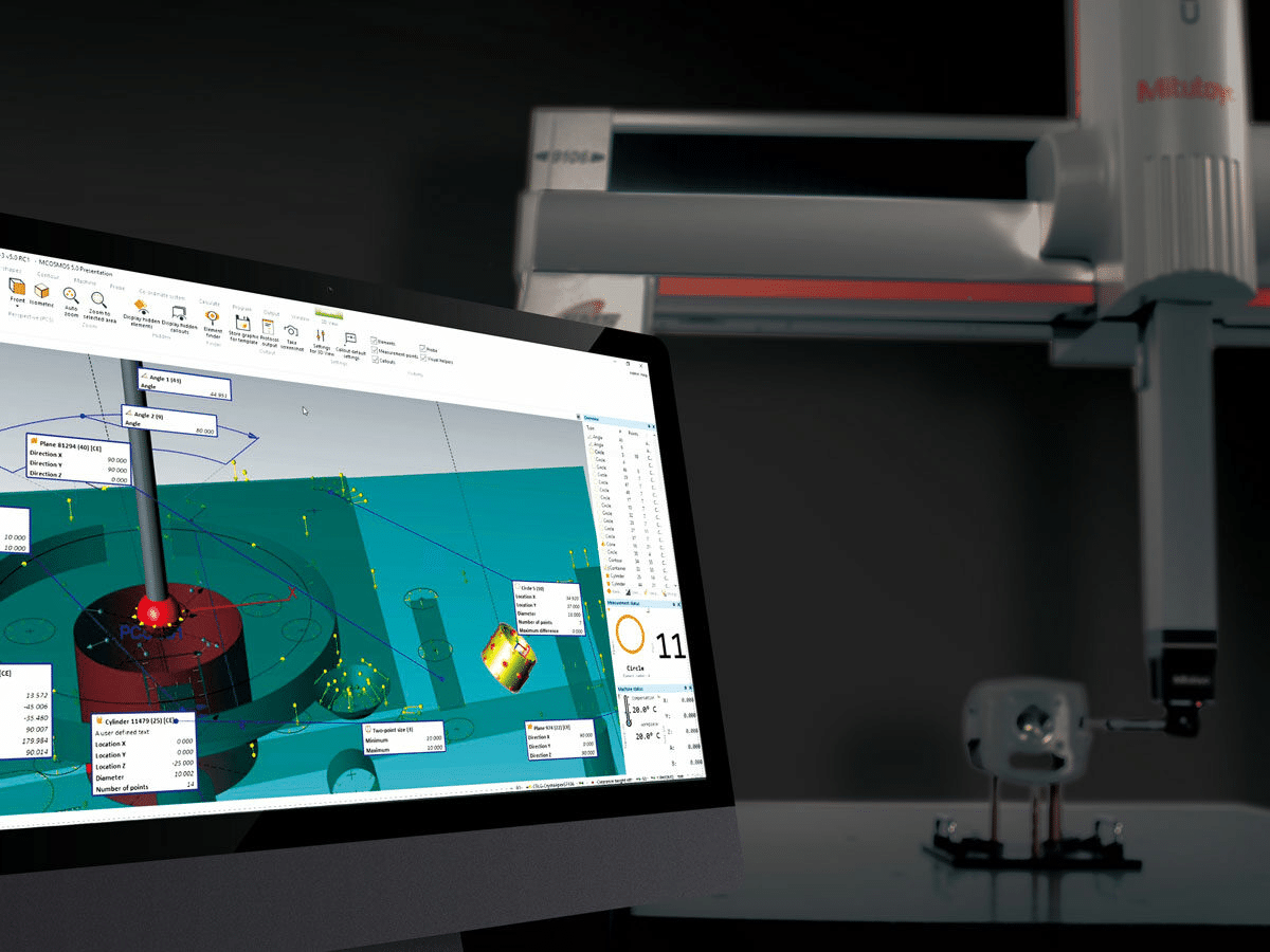
Why Should Inspection Be Considered During Design?
Inspection should be considered during design because a feature that cannot be measured reliably can create supplier disputes, delayed approval, and quality risk.
The Best CNC Parts Protect Function While Eliminating Avoidable Manufacturing Risk
The best CNC parts are not always the simplest parts. They are parts where each feature has a functional reason, a practical manufacturing path, and a reliable inspection method.
DFM should focus on risk reduction rather than blind simplification. A critical sealing surface should stay controlled. A functional bore should stay precise. A non-critical cosmetic edge should not carry the same manufacturing burden.
Geometry, material selection, tolerance strategy, datum planning, surface finish, and inspection all work together. If one area is ignored, the part may become expensive, unstable, or difficult to approve.
Strong DFM protects product performance while removing avoidable machining cost, setup complexity, and inspection risk.
References
1. NIST. Challenges In Tolerance Transfer For Additive Manufacturing.
https://tsapps.nist.gov/publication/get_pdf.cfm?pub_id=918584
2. Furferi, R., et al. Tolerance Analysis Methods for the Application of ISO and ASME Standards in Mechanical Design.
https://jamstjournal.com/cn/article/pdf/preview/10.51393/j.jamst.2025020.pdf
3. Fictiv Engineering. Design Requirements for CNC Manufacturability: DFM Masterclass.
https://www.fictiv.com/masterclass/dfm-for-cnc-masterclass/how-design-requirements-drive-cnc-manufacturability
4. Protolabs. Design for Machining Toolkit.
https://www.protolabs.com/resources/design-for-machining-toolkit/
5. GD&T Basics. Design for Manufacturability.
https://www.gdandtbasics.com/design-for-manufacturability/
6. Five Flute Engineering. CNC Machining DFM: Design Guidelines for Milled Parts.
https://www.fiveflute.com/guide/cnc-machining-dfm-design-guidelines-for-milled-parts/
7. Hubs Engineering. How to Design Parts for CNC Machining.
https://www.hubs.com/knowledge-base/how-design-parts-cnc-machining/
