Surface defects can ruin an otherwise perfect CNC part. Many customers return components due to visual flaws that could affect functionality or assembly fit, costing both time and money.
The most common surface defects in precision CNC parts include tool marks, chatter, poor finish, burrs, and material inconsistencies. These defects typically stem from improper tooling, incorrect machine parameters, vibration issues, or unsuitable material handling. Proper identification and prevention are critical for maintaining quality.
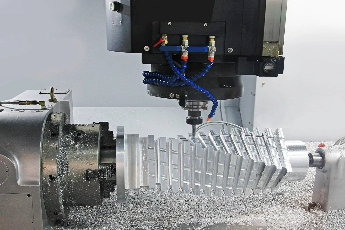
Common surface defects in precision CNC-machined components
In my two decades of running our CNC machining operation, I've encountered virtually every surface defect imaginable. Through trial and error, we've developed effective methods to identify and prevent these issues before they reach our customers. Let me share what I've learned about the most common problems and their solutions.
What Causes Tool Marks in Aluminum Alloy Machining?
Tool marks on aluminum parts can turn a premium component into scrap. When customers receive parts with visible tool lines, they immediately question our quality standards and precision capabilities.
Tool marks in aluminum alloy machining primarily result from dull cutting tools, excessive feed rates, improper tool geometry, or insufficient cooling. These factors cause the tool to drag across the workpiece instead of cleanly shearing the material. Regular tool inspection and replacement help eliminate these unwanted surface artifacts.
Tool marks are visible on the aluminum alloy machined part
Tool marks are among the most frustrating defects we encounter in our CNC shop, especially when working with soft aluminum alloys. The key to eliminating them lies in understanding their root causes and implementing systematic prevention strategies.
The primary factors contributing to tool marks include tool condition, cutting parameters, and cooling approach. Dull tools are the most common culprit – in our experience, aluminum's gummy nature accelerates tool wear, causing cutting edges to drag rather than slice through the material. We've found that implementing a strict tool replacement schedule based on cutting time rather than visual inspection dramatically reduces tool mark occurrence.
Feed rate and cutting speed must be balanced carefully for aluminum. Too aggressive a feed rate creates pronounced tool marks as the cutter can't cleanly shear the material. We typically use higher spindle speeds (around 10,000-15,000 RPM for smaller tools) combined with moderate feed rates to achieve clean cuts.
Tool geometry matters significantly as well. For aluminum, we've found that highly polished tools with sharp cutting edges and positive rake angles significantly reduce tool marks. The specific rake angle depends on the alloy being machined – softer alloys like 6061 benefit from higher positive rake angles (10-15°) compared to harder alloys like 7075.
| Tool Parameter | Recommendation for Aluminum | Impact on Surface Finish |
|---|---|---|
| Rake Angle | 10-15° positive | Prevents material buildup and drag marks |
| Relief Angle | 8-12° | Reduces tool rubbing against workpiece |
| Tool Material | Carbide with polished edges | Provides clean cutting action |
| Coolant Type | Mist or flood cooling | Reduces tool rubbing against the workpiece |
How Does Cutting Speed Affect Surface Finish in Titanium Components?
When machining titanium for aerospace clients, even minor surface imperfections can lead to component rejection. Poor surface finish on titanium parts often means costly rework or complete part rejection.
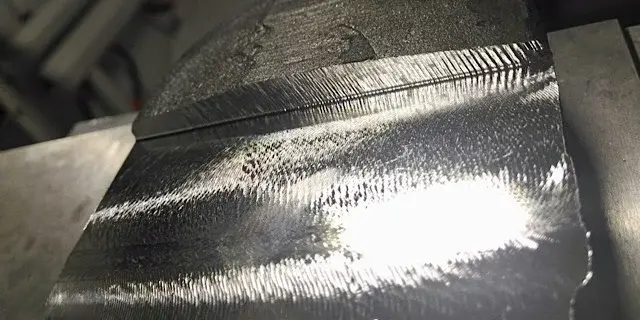
Cutting speed dramatically influences surface finish quality in titanium components. Excessive speeds generate heat that causes built-up edge, material smearing, and thermal damage. Conversely, speeds that are too slow can create rubbing rather than cutting, resulting in rough surfaces. Optimal cutting speeds for titanium typically range between 150-250 SFM.
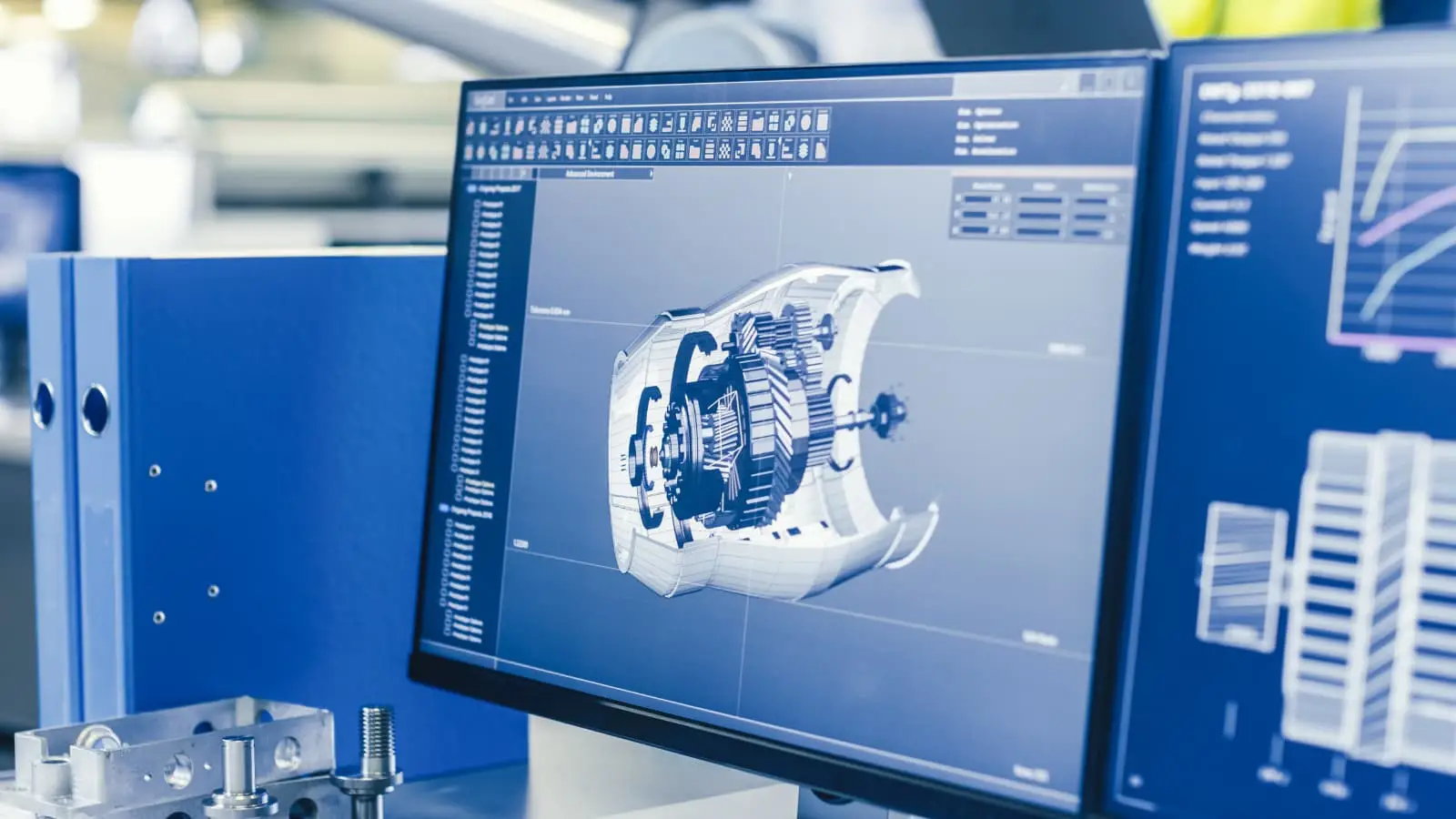
Comparison of surface finishes on titanium components
Working with titanium presents unique challenges that directly impact surface finish quality. Our experience with aerospace and medical device manufacturers has taught us that cutting speed is perhaps the single most critical parameter affecting titanium's surface integrity.
Titanium's low thermal conductivity means heat generated during machining stays concentrated at the cutting zone rather than dissipating through the workpiece. This thermal concentration creates a perfect storm for surface defects if cutting speeds aren't carefully controlled. When speeds exceed recommended parameters (typically above 250 SFM), the excessive heat causes the titanium to react with the cutting tool, creating a built-up edge that transfers irregularities to the machined surface.
We've developed a systematic approach to titanium machining that prioritizes thermal management. For example, when machining Ti-6Al-4V (the most common titanium alloy we work with), we maintain cutting speeds between 150-200 SFM, significantly lower than what we'd use for steel or aluminum. This reduced speed, combined with abundant cooling and rigid toolholding, produces consistent surface finishes below 32 Ra microinches.
Another critical aspect is the cutting tool's condition and geometry. Sharp tools with specialized coatings (particularly AlTiN) perform significantly better, as they reduce friction and heat generation. We implement a strict tool rotation policy for titanium machining – replacing tools after predetermined cutting distances rather than waiting for visual wear signs.
| Cutting Parameter | Optimal Range for Titanium | Effect on Surface Finish |
|---|---|---|
| Cutting Speed | 150-250 SFM | Controls heat generation |
| Feed Rate | 0.004-0.008 IPT | Prevents material tearing |
| Depth of Cut | 0.020-0.040 inches | Maintains cutting stability |
| Coolant Pressure | High (>1000 PSI preferred) | Evacuates chips and reduces heat |
Why Do Vibration Marks Occur in High-Precision Parts?
Vibration marks create wavy patterns that ruin surface finish and dimensional accuracy. These defects are particularly troublesome in high-precision applications where customers demand mirror-like finishes.
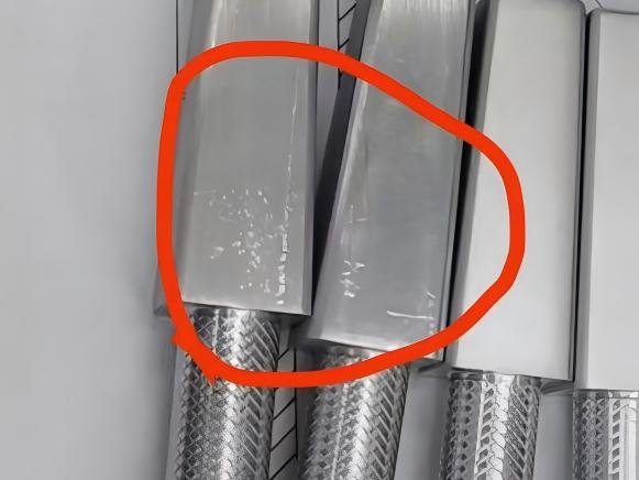
Vibration marks in high-precision parts occur due to machine tool resonance, inadequate workpiece fixturing, imbalanced tooling, or excessive cutting parameters. These vibrations translate directly into the workpiece surface as wavy patterns or chatter marks. Proper workholding, balanced tooling, and optimized cutting parameters help eliminate vibration-induced defects.
Magnified view of vibration marks on the machined surface
Vibration marks represent some of the most challenging surface defects to troubleshoot in our precision machining operations. After years of dealing with these issues, I've found that eliminating vibration requires a comprehensive approach addressing multiple factors simultaneously.
The fundamental cause of vibration marks is the relative movement between the cutting tool and workpiece that shouldn't occur during machining. This unwanted movement creates a harmonic pattern that gets transferred to the part surface. From our experience, the most common sources include insufficient workpiece rigidity, tooling imbalance, and machine resonance issues.
Workholding plays a critical role in preventing vibration. We've invested heavily in premium fixturing systems that maximize contact area with the workpiece. For thin-walled parts particularly prone to vibration, we often employ custom fixtures with supporting elements that minimize deflection during machining. In extreme cases, we'll temporarily fill hollow sections with specialized damping compounds that get removed after machining.
Tool overhang is another major contributor to vibration problems. We follow the rule that tool projection should never exceed 4 times the tool diameter whenever possible. When longer tools are necessary, we use specialized anti-vibration toolholders with internal damping mechanisms. These holders cost significantly more but pay for themselves through improved surface finish and extended tool life.
Machine condition also significantly impacts vibration tendency. We implement a rigorous maintenance schedule that includes regular checking of spindle runout, machine way lubrication, and bearing condition. Our most precise parts are always routed to our newest machines with the highest rigidity characteristics.
| Vibration Source | Prevention Strategy | Implementation Approach |
|---|---|---|
| Workpiece Rigidity | Enhanced fixturing | Custom fixtures, additional clamping points |
| Tool Deflection | Minimize overhang | Keep projection under 4× tool diameter |
| Machine Resonance | Speed/feed optimization | Identify and avoid problematic RPM ranges |
| Cutting Forces | Optimize tool path | Maintain consistent chip load |
What Quality Control Measures Prevent Surface Defects in Aerospace Components?
Aerospace customers have zero tolerance for surface defects. Rejections due to surface quality issues can damage our reputation and jeopardize valuable contracts in this demanding sector.
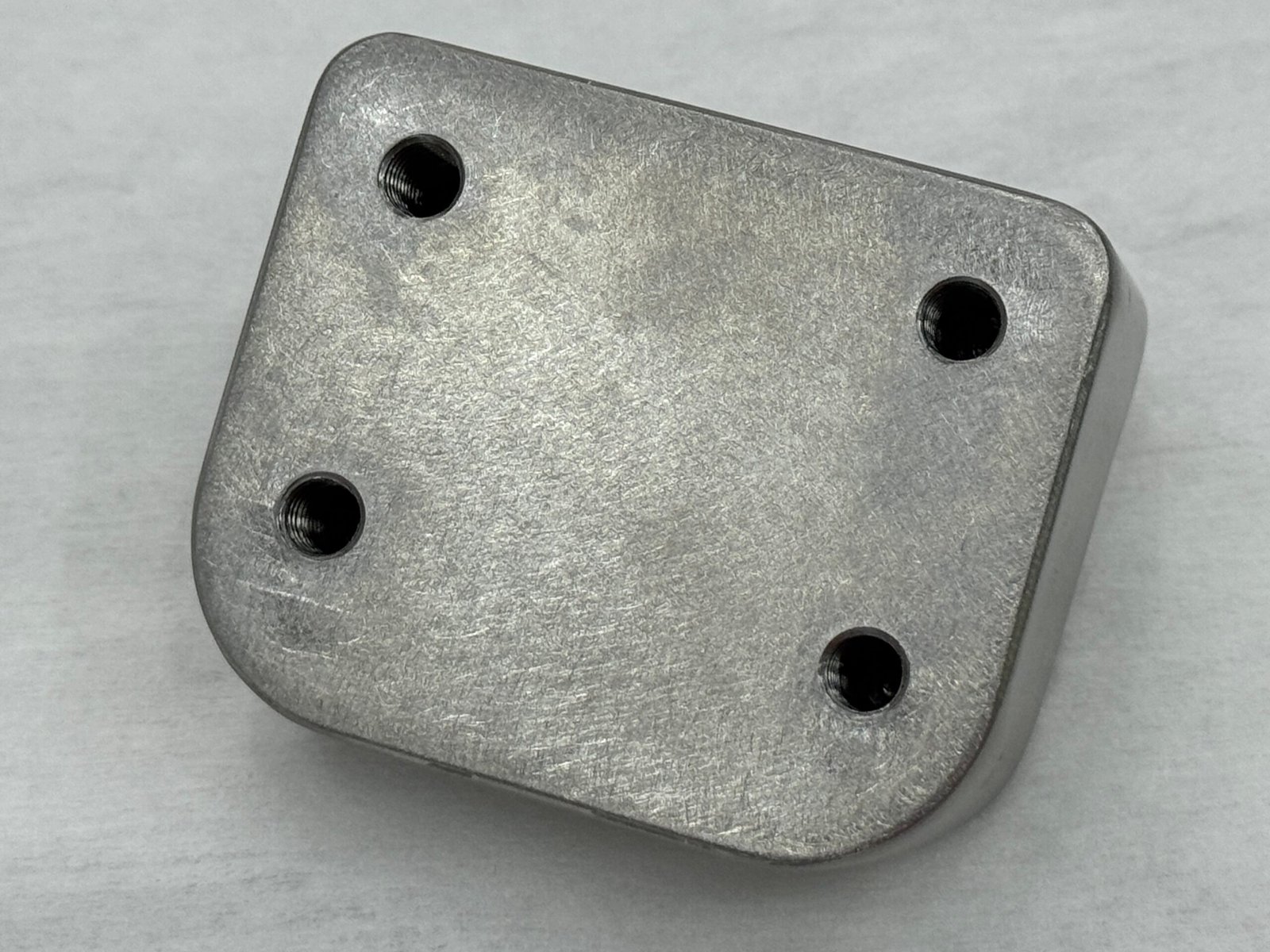
Effective quality control measures for aerospace components include in-process inspection, comprehensive surface measurement protocols, detailed documentation, and statistical process control (SPC). These systems detect and address potential surface defects early, ensuring parts meet strict aerospace specifications for surface roughness, waviness, and defect-free requirements.
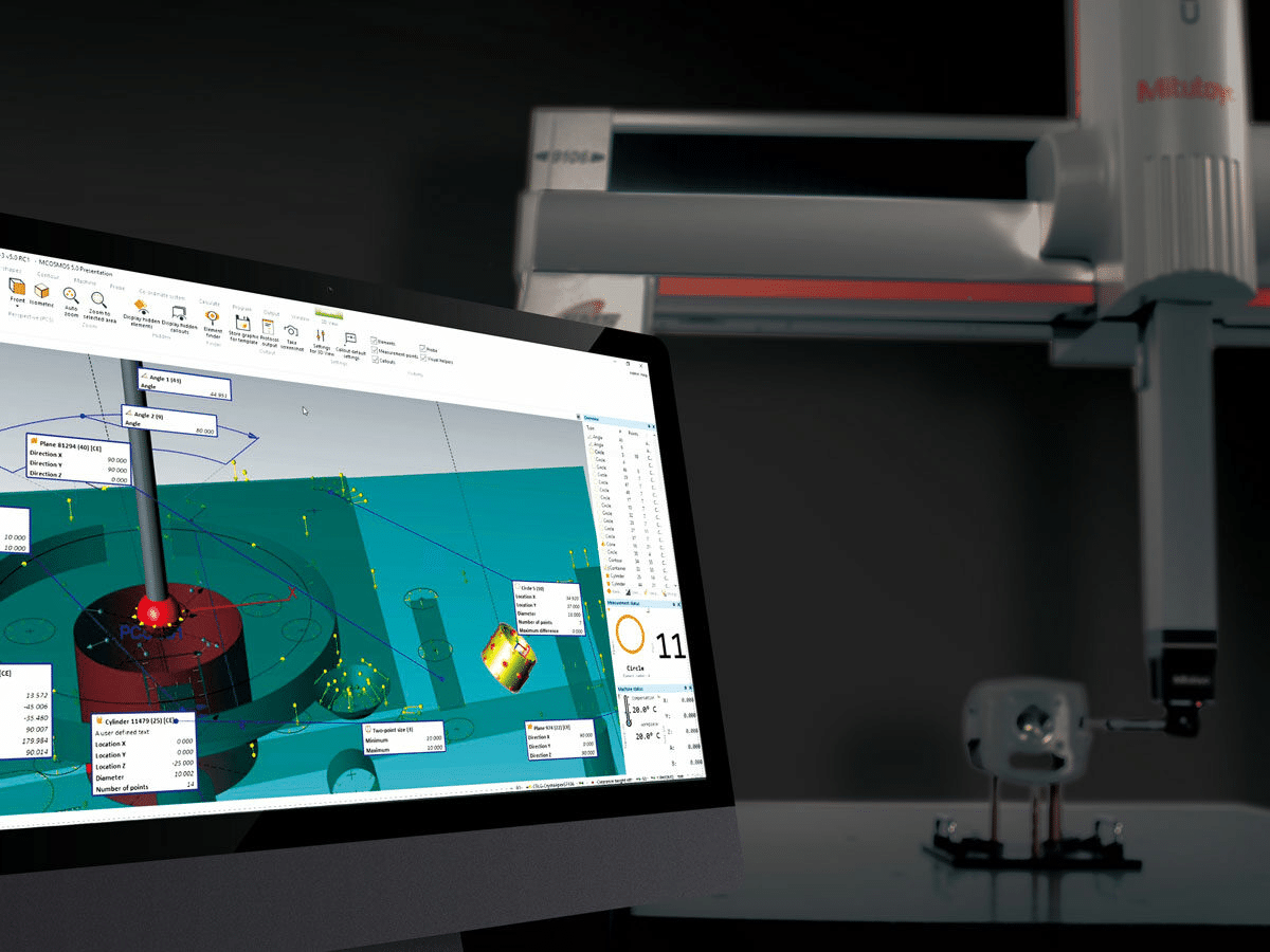
Surface inspection of a precision aerospace component
In our experience manufacturing components for aerospace clients, preventing surface defects requires implementing multiple layers of quality control throughout the entire production process. Over the years, we've developed a comprehensive approach that has significantly reduced defect rates and customer rejections.
Our quality control system begins with incoming material verification. We've learned that material inconsistencies often manifest as surface defects later in the process. Every batch of raw material undergoes testing for composition, hardness, and internal structure before entering production. This pre-emptive inspection has helped us identify problematic material batches that would likely have resulted in surface quality issues.
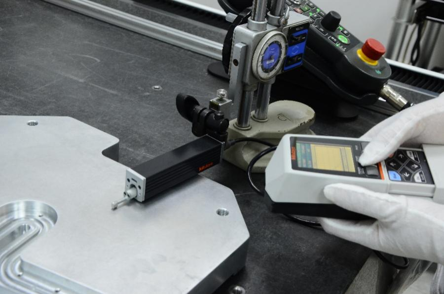
During machining, we implement in-process verification steps at critical points. Our operators use calibrated surface roughness testers to check finish quality after key operations, comparing results against established parameters. These checks allow us to catch potential issues before additional machining steps compound the problem. We've programmed our CNC machines to pause at specific intervals, enabling operators to perform quick surface inspections without removing the part from the fixture.
For final inspection, we use a combination of visual examination under controlled lighting, surface profilometry, and occasionally advanced techniques like white light interferometry for the most demanding applications. Our inspection protocols distinguish between different types of surface characteristics – roughness, waviness, and flaws – as each has different acceptance criteria in aerospace applications.
| Inspection Stage | Methods Used | Acceptance Criteria |
|---|---|---|
| In-Process | Portable surface roughness testing | Ra value within 80% of specification |
| First Article | Complete surface mapping, visual inspection | Full compliance with drawing requirements |
| Final Inspection | Controlled lighting, magnification, and profilometry | Zero defects, full documentation |
| Statistical Analysis | SPC charts for surface parameters | Process Cpk >1.33 minimum |
How Can Material Selection Impact Surface Finish Quality?
Choosing the wrong material leads to persistent surface finish problems that no amount of process optimization can fix. Customers often blame our machining when the root cause lies in unsuitable material properties.
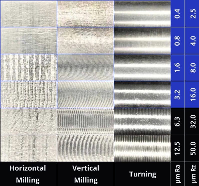
Material selection significantly affects achievable surface finish quality in CNC machining. Materials with inconsistent grain structure, inclusions, or poor machinability ratings inherently produce inferior surfaces. Free-machining grades of aluminum, stainless steel, and titanium typically yield better finishes than their standard counterparts due to chip formation characteristics and reduced tool wear.
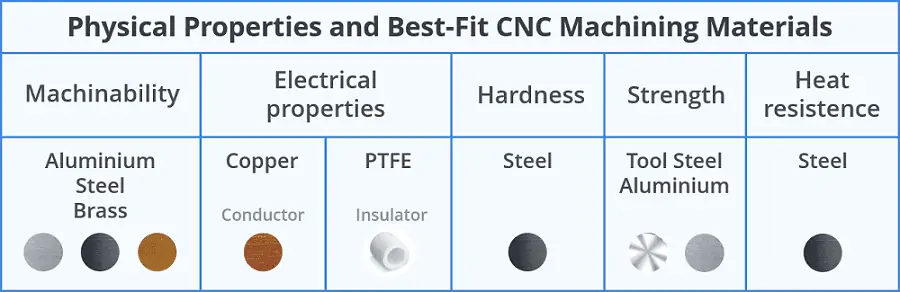
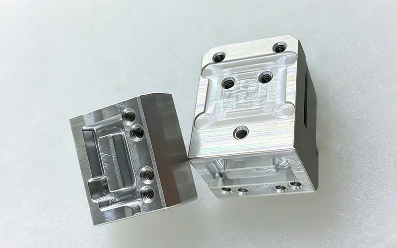
CNC machining comparison across different materials
Material properties have profound effects on surface finish quality that many engineers and designers overlook. In our decades of machining experience across diverse industries, we've observed clear patterns in how different materials respond to identical machining processes.
The microstructure of the material plays a crucial role in determining surface finish potential. Materials with homogeneous structures generally produce more consistent finishes than those with directional grains or inclusions. For example, when machining 6061-T6 aluminum, we consistently achieve surface finishes below 32 Ra microinches, while 7075-T6 with its more complex microstructure typically yields surfaces in the 63 Ra range using identical cutting parameters.
For stainless steels, the difference between standard and free-machining grades is dramatic. Standard 304 stainless often produces built-up edge and poor surface finish, while 303 stainless (with added sulfur) machines to excellent surface finishes with proper tooling. The sulfur content creates microscopic discontinuities that promote chip breaking and reduce cutting forces, resulting in superior surface quality.
Heat treatment conditions also significantly impact machined surface quality. We've found that annealed materials often produce poorer surface finishes due to their tendency to "push" rather than cut cleanly. Conversely, age-hardened materials typically machine to better finishes but require more rigid setups and sharper tools to prevent work hardening during cutting.
Material homogeneity is another critical factor. Cast materials with potential porosity or inclusions present particular challenges for surface finish. We've learned to identify these issues through preliminary cuts that reveal the material's internal structure before proceeding with precision finishing operations.
| Material Type | Surface Finish Potential | Key Factors Affecting Finish |
|---|---|---|
| Aluminum Alloys | Excellent (8-32 Ra) | Alloy composition, temper condition |
| Stainless Steel | Fair to Good (32-63 Ra) | Grade, sulfur content, work hardening |
| Titanium Alloys | Fair (63-125 Ra) | Alpha vs. beta structure, heat treatment |
| Tool Steels | Good (16-32 Ra) | Heat treatment, carbide distribution |
| Cast Materials | Poor to Fair (125-250 Ra) | Porosity, inclusion content, grain structure |
Conclusion
Surface defects in precision CNC parts stem from multiple interrelated factors spanning tooling, parameters, fixturing, and material properties. By systematically addressing these variables and implementing robust quality controls, we consistently produce defect-free components that meet the most demanding specifications.