Fundamentals of Thin Wall Machining
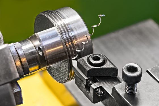
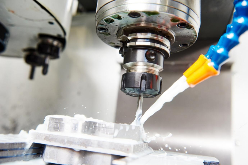
Thin wall machining is a CNC machining process focused on creating precise cuts and shapes in materials with thicknesses typically less than 2mm. Its main objective is to manufacture intricate components with delicate, thin features that demand the utmost accuracy.
Applying thin wall CNC machining to different materials presents different challenges. Metals that are common include titanium, aluminum, and stainless steel. These materials are strong and durable, and handling them carefully is necessary to prevent deformation. Polymers, such as ABS and polycarbonate, are also widely used materials because of their flexibility and low weight, although poor machining can cause them to distort. Due to their exceptional strength-to-weight ratios, composite materials—like carbon fibre-reinforced polymers—are becoming more and more popular. However, in order to avoid delamination or fiber pull-out, these materials require precise machining parameters. To ensure accurate and high-quality thin wall components, it is necessary to fully understand the attributes of each material in order to optimize feed rates, cutting speeds, and tool paths.
Applications of thin wall processing
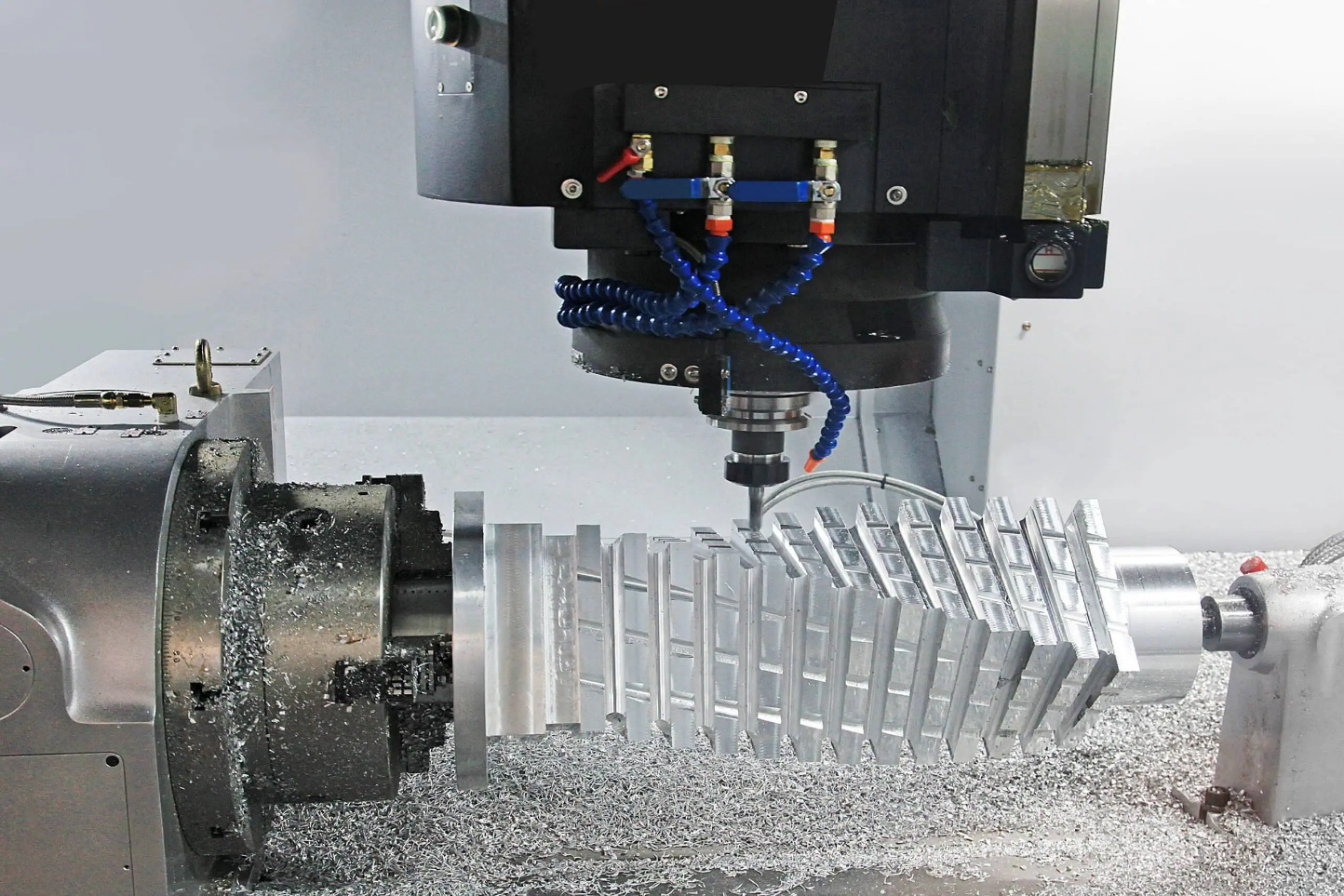
Thin-wall machining is important to many industries, but it's especially important to the aviation industry, where it's needed to make complex enclosures and lightweight structural parts.
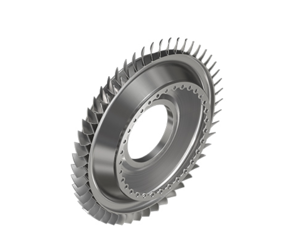
This method is essential to the aerospace industry for producing parts like blisks, hubs, ribs, frames, skin panels, stringers, bulkheads, and turbine blades. The purpose of these parts is to reduce the amount of mechanical assembly required, therefore there are no bolts or rivets, and the component is uniform throughout.
Beyond aerospace, thin-wall machining finds application in other sectors, like automotive, where high-strength and lightweight components are becoming more and more important. The production of advanced and precise surgical equipment and implants help the medical industry as well. Thin-wall machining is also used in the electronics industry to make durable, lightweight enclosures for a range of equipment.
Challenges Encountered in Thin Wall Machining
There are many challenges in thin-wall CNC machining, chief among them being vibrations resulting from the walls' poor stiffness. There are two kinds of vibrations that can be distinguished: forceful and self-induced (chattering).
When the system's natural frequency response (FRF) is stimulated during the milling process, chatter happens. This instability is typically linked to vibrations in the tool, but it is more important to consider the part's FRF, which is continuously changing as a result of geometric differences. An unstable machining process results from the FRF changing along with the part's shape. The operation may become unstable as a result of this cyclical tendency, leaving scars on the component that lower the overall surface quality.
Conversely, forced vibration occurs when there is not enough stiffness in the part to keep the chip thickness constant. Under the cutting forces, both the tool and the workpiece deform, resulting in vibrations that occur at the same frequency as the spindle speed or its multiples. By modifying the contact dynamics between the tool and the workpiece, this deflection modifies the chip width and influences the cutting forces. These instabilities frequently lead to surface flaws, which make the final product rougher.
Another significant challenge associated with the low stiffness of thin walls is the dimensional errors caused by part deflection. Thin walls are subject to significant static deflection because of cutting pressures, in contrast to stiff sections. Cutting parameters—which specify the cutting forces and, hence, the deformation of the system—and the selected machining approach (up or down-milling) have an impact on this deflection. Although deflection isn't usually completely eliminated, high-speed milling helps lessen residual tensions and cutting forces. Because the part's geometry varies in real time, mirror milling in particular makes this problem worse.
Furthermore, as the size and shape of the pieces utilized in thin-wall machining increase, so does the complexity. Double curve procedures produce skins that frequently misalign with the clamping mechanism, resulting in overcutting. Maintaining machining tolerances with conventional work holding and fixtures is more difficult when dealing with larger pieces than monolithic blocks. It is especially challenging to maintain accuracy and produce high-quality finishes because of this misalignment and the overcutting that follows.
Selecting the Optimal Tools
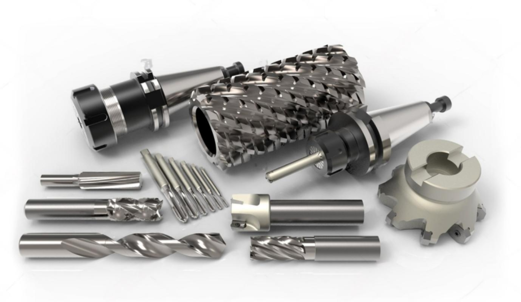
The correct tool selection is critical to thin-wall machining success. Important considerations are the material to be machined, the desired level of polish, and the necessary dimensional tolerances.
To reduce distortion and increase precision while working with sensitive materials such as plastic or aluminum, utilizing specialist tools with smaller diameters and lower cutting heights. The stability and quality of the process are affected by the cutting performance and material removal rates that are greatly impacted by the geometry of the tool and the cutting edge angles.
Tools with high-performance coatings, including diamond-like carbon (DLC) or titanium nitride (TiN), are more efficient and durable. Furthermore, higher helix angle tools yield better surface quality and chip evacuation.
Determining the Best Cutting Speeds and Feed Rates
When it comes to CNC machining, especially thin-wall machining, cutting speed and feed rate are essential variables. For the finest outcomes, it is essential to adjust these settings to suit the particular material.
In general, faster material removal and higher productivity are caused by higher cutting speeds. On the other hand, precision and quality must be balanced with speed. Overly fast cutting speeds can worsen the quality of the finished product by generating unwelcome material deformation, higher heat, and excessive tool wear.
Another important factor is feed rate, which records the speed at which the cutting tool passes through the material. The surface finish and dimensional accuracy of the item are greatly impacted. Appropriate feed rate selection prevents problems such as excessive vibration and tool deflection and guarantees a smoother finish and accurate dimensions.
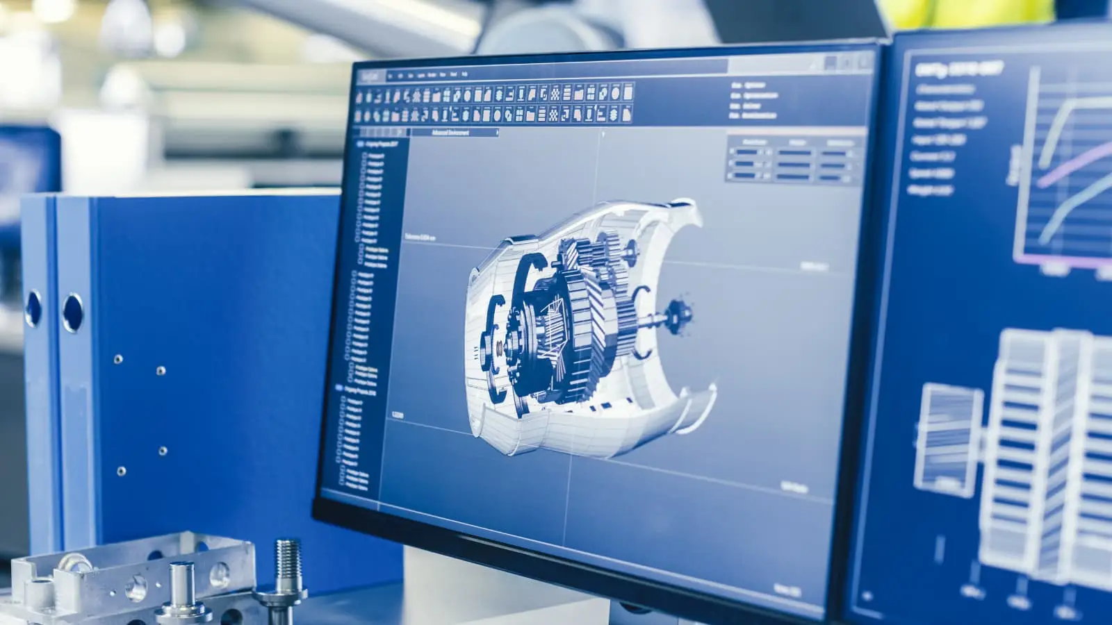
Optimizing the Tool Path
In thin-wall machining, the path taken by the cutting tool through the material is known as the tool path. In order to limit material deformation and achieve the intended outcomes, this path must be optimized.
There are various tool path optimization techniques that can be used, each with advantages and disadvantages. Continuous, smooth cutting is facilitated by spiral tool paths, which lessen the likelihood of sudden direction changes that could induce vibrations. In order to minimize tool deflection and maintain constant cutting conditions, adaptive tool paths dynamically adapt to the geometry of the material. Because of their accuracy and adaptability, 3-axis tool paths are appropriate for intricate geometries, but they may need to be carefully planned to prevent unnecessarily large tool motions.
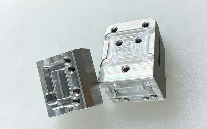
Effective Work Holding Solutions
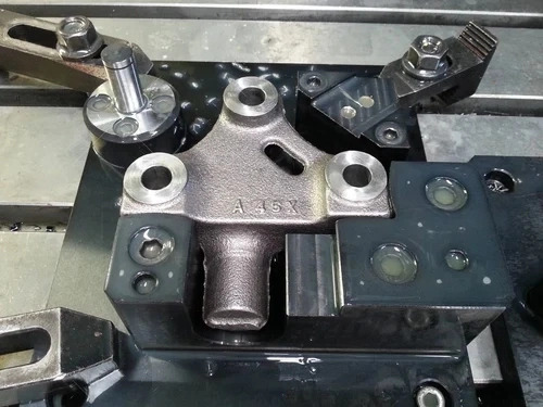
CNC Fixture
Work-holding solutions are the key to efficiently preventing instabilities in thin-wall machining. This method frequently works better than just modifying the cutting settings, particularly when it comes to items whose Frequency Response Function (FRF) is difficult to quantify and varies greatly during the machining process.
Fixtures and Work-holdings
One common option for fastening thin-wall components is using vacuum fixtures. There are two primary types available: flexible vacuum cups and bespoke vacuum systems. Although more expensive and confined to particular pieces, customized vacuum systems offer a stronghold thanks to specialist equipment made for each individual part. However these systems can cause the part to experience tensile stress, which could result in deformation. Conversely, flexible vacuum cups or beds enhance flexibility and lessen vibrations and deflection by conforming to the shape of the item using adjustable pins and vacuum caps.
For components like impellers, blades, and blisks, hydraulic chucks or special jaws are often employed. In the early roughing stages, these effectively avoid vibrations and deflection by lowering clamping pressure and minimizing in-process deformation. With adjustable workholdings that offer support at ideal positions, performance can be further improved. With placements determined by simulations and supports put at the most flexible points, some commercial workholdings, for example, are made to offset cutting energy across the part. In order to enable real-time modifications and the gathering of historical data for operational guidance, these systems frequently come equipped with integrated sensors.
Moving Fixtures
Moving fixtures synchronize the movement of the tool with the workpiece to maintain stability when cutting low-rigidity items. A supporting piece that moves collinearly with the tool path in this technique—often referred to as "mirror milling"—effectively supports the cutting forces. The amplitude of vibration and distortion are greatly reduced by this technology, improving the surface finish. An air jet system that is synced with the cutting head is another technique that reduces deflection and serves as a dynamic support. By significantly lowering workpiece vibration, this air jet aid can enhance surface quality and thickness accuracy. These solutions, however, are usually restricted to simpler geometries and might not be flexible enough for parts that are more complicated.
For fuselage panels, a more sophisticated moving fixture employs a magnetic work-holding system consisting of two sets of magnets. The master magnets follow the tool trajectory, while the slave magnets on the panel back provide compensatory support through magnetic attraction. By minimizing frictional forces, this system minimizes thrust forces during milling. In order to optimize tool paths, these methods necessitate a substantial investment and pre-measuring techniques. Nevertheless, some manufacturers have produced mirror milling centers with double-head mechanisms that offer simultaneous cutting and support.
Active Damping Actuators
Active damping actuators use eddy current damping (ECD) or piezoelectric sensors to adjust to changing conditions and prevent vibrations. The machining stability can be significantly improved by these technologies. Work-holding systems with piezo-actuators included in them reduce vibrations, enhancing surface quality and prolonging tool life. ECD devices significantly reduce machining vibrations by using electromagnetic induction to generate repulsive forces. The limiting depth of cut can be greatly enhanced by active dampening, preserving stability and accuracy while milling.
Stiffening Devices
Stiffening devices increase the workpiece's rigidity. It has been demonstrated that techniques like mass compensation systems, low melting point alloys (LMPA), and magnetorheological fluids (MRF) work well. Under a magnetic field, MRFs change from liquid to semi-solid, offering flexible support. During machining, LMPAs fill the spaces between the part and the fixture, solidifying to provide rigidity and then melting away without causing any damage to the product. Viscoelastic dampers and energy-absorbing foams are examples of mass compensation devices that can be customized to the geometry of the workpiece in order to reduce vibrations.
Tips and Best Practices for Success
In thin wall machining, it might be difficult to achieve dimensional accuracy and straightness. To increase your success with thin wall milling, remember these crucial pointers:
- Use the Right Tooling: To preserve tool strength while reaching deeper depths, use necked-down tooling. By measuring the length below the shank (LBS), deep-pocket milling friction is reduced and appropriate chip removal is guaranteed.`Use the Right Tooling: To preserve tool strength while reaching deeper depths, use necked-down tooling. By measuring the length below the shank (LBS), deep-pocket milling friction is reduced and appropriate chip removal is guaranteed.
- Determine Appropriate Depth of Cut: To support the wall, use a stepped-down technique for axial depth of cut (ADOC). Due to material hardness, this separates the overall wall height into manageable depths. Using a progressive method, lowering tool pressure as wall height rises and switching sides to maintain stability is how to achieve radial depth of cut (RDOC). For reduced vibration and better surface polish, use light passes at the end.
- Climb milling: This method ejects chips behind the cutter while reducing heat and friction. Channeling heat into the chip instead of the tool or workpiece, it extends the life of the tool, lowers costs, and improves component polish.
- Wall Stabilization: For manual vibration dampening and wall stabilization, use thermoplastic compounds or wax (which may be readily removed thermally).
- HEM Toolpaths: To improve material removal rates, minimize tool wear, and maximize tool performance, High-Efficiency Milling (HEM) blends low RDOC with high ADOC and increased feed rates.
Packing notes for thin wall processing products

bubble wrap inside a cardboard box
Thin wall machining items must be packaged carefully to avoid damage during transportation. Securely cradle each component, reducing movement, using foam inserts or bespoke molds. To buffer against collisions, cover each component in a protective layer of soft foam or bubble wrap. Make sure the package is well-made and marked "fragile" so that handlers know to take caution. Ample padding between layers should be used when double-boxing for additional protection. A well-packed set of parts preserves the quality and dimensional accuracy of your precision-machined components even after they are delivered.