


Basics of Welding
Welding is a material joining process where two or more parts are coalesced at their contacting surfaces through the application of heat and/or pressure. After being brought together, the surfaces that need to be joined referred to as faying surfacesᅳcombine and create a strong bond. Metals are the most frequently utilized materials in this procedure; however, plastics can also be employed. Sometimes, to help with the coalescence, a filler substance is introduced. Weldment is the term used to describe the final assembly of linked elements. Welding can be performed using heat alone, a combination of heat and pressure, or pressure alone without external heat. Specific welding techniques can be used to fuse dissimilar metals together; however, they are primarily employed to join portions formed of the same metal.
Types of Welding Processes
Welding processes can be divided into two main groups: solid-state welding and fusion welding.
Fusion Welding
Fusion welding processes use heat to melt the base metals, often with added filler metal to enhance the molten pool and strengthen the weld. When no filler metal is used, the weld is called autogenous. The most popular welding techniques fall within the fusion category and are often grouped into the following categories:
Arc Welding (AW)
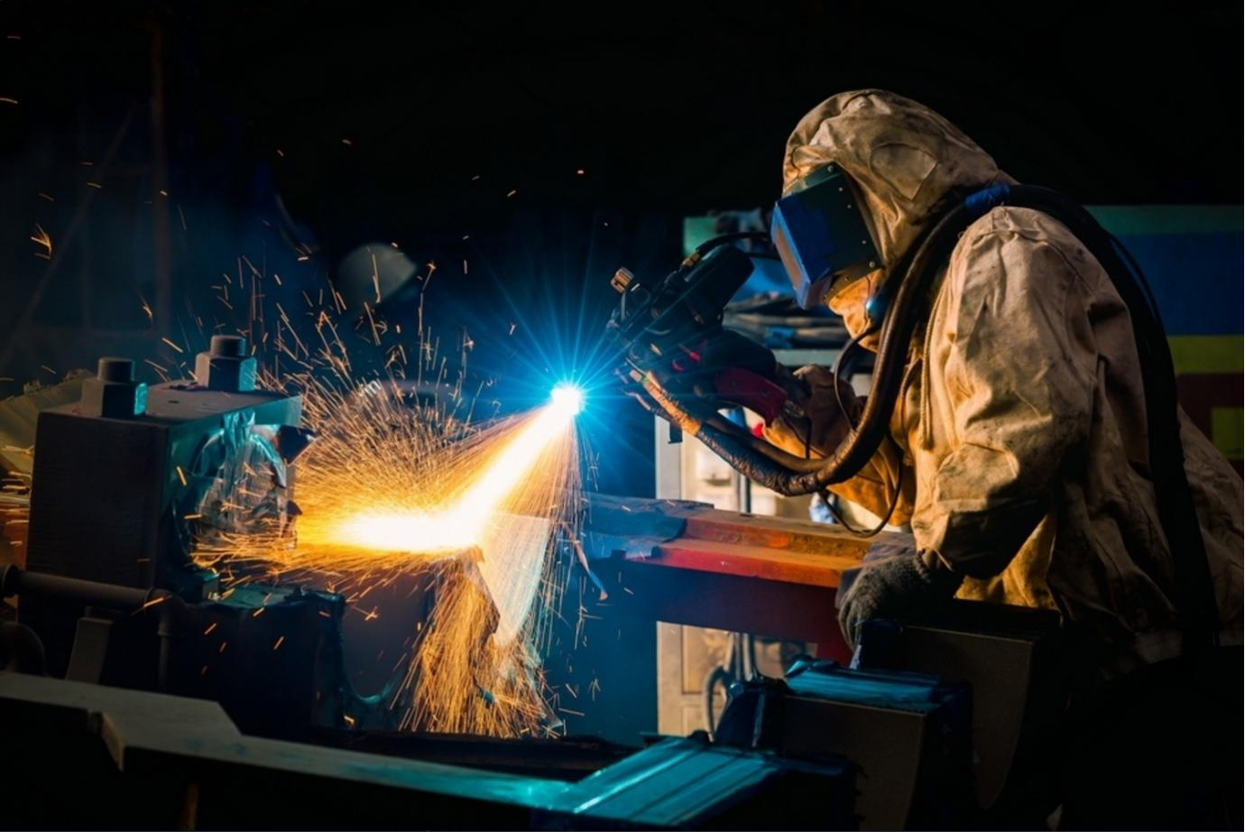
Arc welding is a group of welding techniques wherein the metals are heated using an electric arc, as demonstrated below. Most arc-welding procedures use a filler metal, and some also apply pressure while the process is underway.
An electric arc is produced when an electric current flows over a circuit gap, causing a column of gas to become thermally ionized and sustain the arc. In arc welding (AW), the electrode briefly makes contact with the workpiece before rapidly separating to generate the arc. Any metal can be melted by the extreme heat produced by this arc, which can reach temperatures of up to 10,000°F (5500°C). Melting base metal and, if applicable, filler metal combine to generate a pool of molten metal close to the electrode tip. Usually, this filler metal is added to improve the volume and strength of the weld connection. The molten weld pool behind the electrode hardens as it moves along the joint.
The welder can manually control the electrode's position in relation to the workpiece, or they can use mechanical techniques like machine, robotic, or automatic welding. Arc time, also known as arc-on time, is the ratio of actual welding time to total hours spent. In manual arc welding, the quality of the weld greatly depends on the ability and dedication of the welder.
Arc time is calculated as (hours worked) / (time arc is on).
Both individual welders and automated workstations can benefit from this idea. Arc duration for manual welding is usually about 20% because the operation necessitates significant hand-eye coordination under demanding conditions, and rest intervals are important to prevent tiredness. However, depending on the particular operation, arc time in robotic, automatic, and machine welding might rise to about 50%.
Resistance Welding (RW)
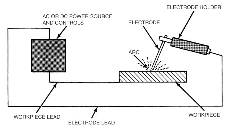
Resistance welding, also known as electric resistance welding (ERW), achieves coalescence by applying heat generated by electrical resistance to the current flow between the faying surfaces of two components that are being held together under pressure. The primary components involved in resistance welding are illustrated in the figure below, showcasing a resistance spot-welding operation, which is the most commonly used method in this category.
These components consist of the workpieces to be welded (typically sheet metal parts), two opposing electrodes, a mechanism to apply pressure and squeeze the parts together, and an AC power supply that provides a controlled current. The process creates a fused area between the two parts, known as a weld nugget in spot welding. Unlike arc welding, resistance welding does not require shielding gases, flux, or filler metal; and the electrodes that deliver electrical power are non-consumable. Resistance welding is considered a type of fusion welding because the applied heat usually melts the faying surfaces. However, there are exceptions. Some resistance heating-based welding operations utilize temperatures below the melting points of the base metals, preventing fusion from occurring.
Oxyfuel Gas Welding (OFW)
Oxyfuel gas welding (OFW) encompasses a variety of welding operations that use different fuels combined with oxygen to perform welding tasks. The key difference among these processes is the type of gas used. OFW is also commonly utilized in cutting torches to slice through and separate metal plates and other materials. The most significant process within this group is oxyacetylene welding.
Oxyacetylene welding (OAW) is a fusion welding technique that employs a high-temperature flame produced by the combustion of acetylene and oxygen, directed by a welding torch. A filler metal may be added, and sometimes pressure is applied between the contacting surfaces during the process. When filler metal is used, it usually comes in rod form, with diameters ranging from 1.6 to 9.5 mm (1/16 to 3/8 inches). The filler metal's composition must closely match that of the base metals. Often, the filler rod is coated with flux to clean the surfaces and prevent oxidation, resulting in a stronger weld joint. Acetylene (C2H2) is the most preferred fuel in the OFW group because it can achieve the highest temperatures, reaching up to 3480°C (6300°F).
Electron beam (EB) welding
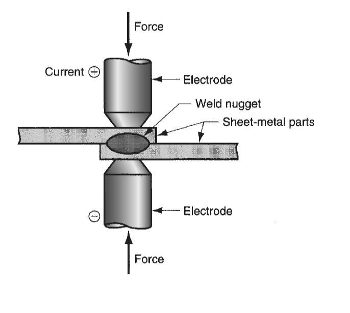
Electron-beam welding (EBW) is a fusion welding method where heat is generated by directing a highly focused, intense stream of electrons onto the work surface. The equipment used in EBW is similar to that used in electron-beam machining. The electron beam gun operates at high voltages, typically ranging from 10 to 150 kV, to accelerate the electrons, while the beam currents remain low, measured in milliamps. Although the overall power in EBW may not be extraordinarily high, the power density is exceptionally significant. This high-power density is achieved by focusing the electron beam onto a very small area of the work surface.
The power density (PD) in EBW can be calculated using the formula:
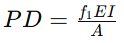
where PD represents power density in W/mm² (convertible to Btu/sec-in² by dividing by 1055), f1 is the heat transfer factor (with typical values for EBW ranging from 0.8 to 0.95), E is the accelerating voltage in volts, I is the beam current in amps, and A is the work surface area in mm². Typical weld areas for EBW range from 0.013 to 2.0 mm².
Laser beam welding
In laser welding, also known as laser beam welding (LBW), the materials are melted using a concentrated laser heat source, allowing them to merge as they cool. Owing to the concentrated heat produced by the laser, welding may be done at high speeds—measured in meters per minute—for thin materials and can produce narrow, deep welds with square-edged pieces in thicker materials.
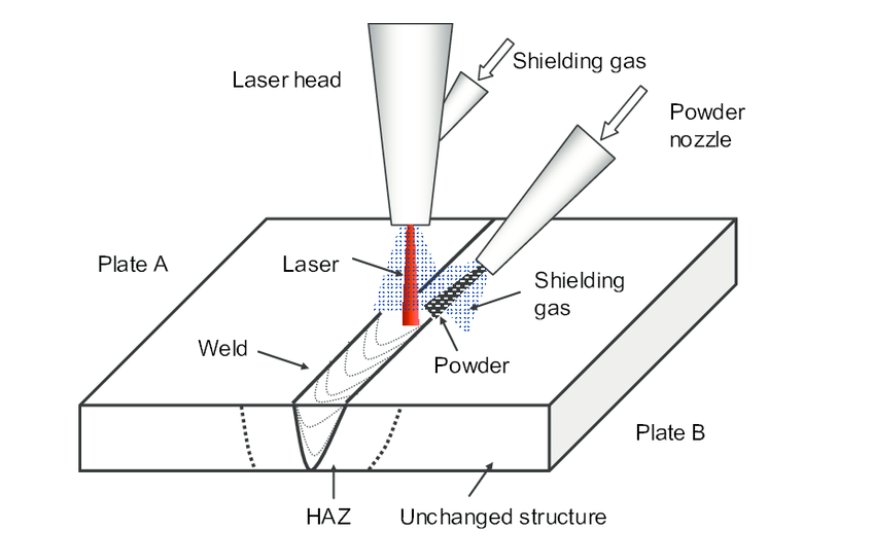
The abbreviation "laser" refers to light amplification by stimulated radiation emission. Laser-beam machining is another application of this technology. To avoid oxidation, LBW is commonly carried out using shielding gases such as carbon dioxide, argon, nitrogen, and helium; filler metal is typically not included. Similar to electron-beam welding, this method yields high-quality welds with deep penetration and a narrow heat-affected zone. As a result, comparisons between LBW and EBW are common.
Compared to EBW, LBW has a few advantages: it doesn't need a vacuum chamber, doesn't release X-rays, and its laser beams may be concentrated and directed with the use of mirrors and optical lenses. But unlike EBW, LBW is unable to reach the same depth and high depth-to-width ratios. While EBW can produce weld depths of up to 50 mm (2 inches), laser welding can only achieve maximum weld depths of about 19 mm (0.75 inches). In LBW, depth-to-width ratios are normally restricted to approximately 5:1. LBW is widely utilized for small component joining because of the highly concentrated energy in the narrow beam area of the laser.
Solid-State Welding
Solid-state welding encompasses a range of joining techniques where the coalescence of the joining surfaces is achieved without melting, using pressure with or without additional heat. Typical welding procedures in this category include the following:
Diffusion Welding (DFW)
Diffusion welding (DFW) involves holding two surfaces together under pressure at a high temperature, allowing the parts to coalesce through solid-state diffusion.
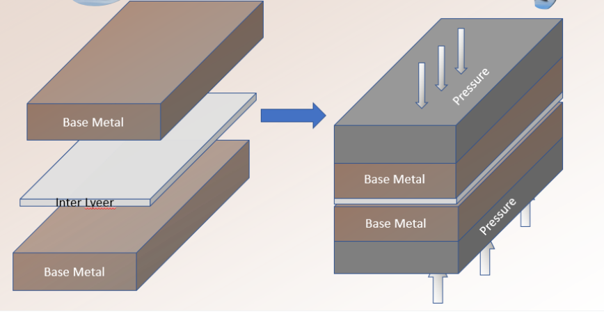
The temperatures used are significantly lower than the melting points of the metals, reaching up to about 0.5 Tm (melting temperature), with minimal plastic deformation at the surfaces. The primary bonding mechanism is solid-state diffusion, where atoms migrate across the interface of the contacting surfaces. DFW is often employed in the aerospace and nuclear industries to join high-strength and refractory metals. It is suitable for joining both similar and dissimilar metals, with a filler metal layer often placed between different base metals to enhance diffusion. The diffusion process can be lengthy, sometimes taking over an hour.
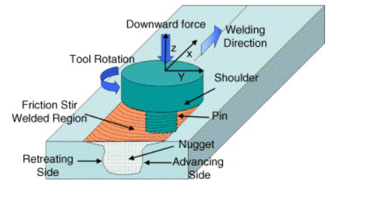
Friction Stir Welding (FSW)
Friction stir welding (FSW) is a solid-state welding technique where a rotating tool moves along the joint line between two workpieces, generating heat through friction and mechanically stirring the metal to create a weld seam. The process gets its name from the stirring or mixing action involved. Unlike conventional friction welding (FRW), where the parts themselves generate the friction heat, FSW uses a separate wear-resistant tool for this purpose.
The tool used in FSW features a cylindrical shoulder and a smaller probe extending below it. During welding, the shoulder rubs against the top surfaces of the two parts, creating most of the frictional heat, while the probe adds additional heat by mixing the metal along the joint line. The probe’s design is optimized to enhance this mixing action. The heat generated from friction and mixing softens the metal to a highly plastic state without melting it. As the tool advances along the joint, the leading edge of the rotating probe pushes the softened metal around it, forging the metal into a weld seam. The shoulder helps to contain the plasticized metal around the probe.
FSW is widely used in industries such as aerospace, automotive, railway, and shipbuilding. Common applications include butt joints on large aluminum parts. This process can also be used with composites and polymers, as well as other metals like titanium, steel, and copper. The advantages of FSW include little distortion or shrinkage, an appealing weld appearance, excellent mechanical qualities of the weld joint, and the removal of harmful fumes, warping, and shielding concerns common to arc welding. Nevertheless, there are certain disadvantages to the procedure, namely the need for strong clamping of the pieces and the creation of an escape hole when the tool is removed.
Ultrasonic Welding (USW)
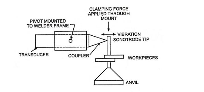
Ultrasonic welding (USW) involves applying a moderate amount of pressure between the two components while using an oscillating motion at ultrasonic frequencies in a direction parallel to the contacting surfaces. This oscillatory motion method, which is frequently employed in lap welding, breaks down surface coatings to enable close contact and a robust metallurgical link between the surfaces. Although some heating occurs due to interfacial rubbing and plastic deformation, the temperatures stay much below the melting point, negating the need for shielding gases, filler metals, or fluxes.
An ultrasonic transducer is coupled to a sonotrode, which transfers the oscillatory motion to the upper workpiece. With an amplitude of between 0.018 and 0.13 mm (0.0007 to 0.005 inches), this transducer transforms electrical energy into high-frequency vibratory motion, usually within the range of 15 to 75 kHz. There is less plastic deformation since USW clamping pressures are substantially lower than those employed in cold welding. It usually takes less than a second to complete the welding process.
USW is mainly used for lap joints on soft materials such as aluminum and copper. Welding harder materials can quickly wear out the sonotrode. The workpieces should be relatively small, with typical welding thicknesses of less than 3 mm (1/8 inch). Applications include wire terminations and splicing in the electrical and electronics industries, eliminating the need for soldering, assembly of aluminum sheet-metal panels, welding tubes to sheets in solar panels, and various small parts assembly tasks.
Automation in Welding
Due to the risks associated with manual welding and the desire to enhance productivity and product quality, different forms of mechanization and automation have emerged. These categories encompass machine welding, automatic welding, and robotic welding.
Machine welding is the term for mechanized welding using equipment that works under the constant supervision of a worker. Usually, a stationary work is moved in relation to a welding head that is moved mechanically, or the work is moved in relation to a stationary welding head. To oversee the operation, a human worker must constantly monitor and communicate with the machinery.
When the machinery can complete the task without the need for human intervention, it is called automatic welding. Usually, a human worker is present to supervise the procedure and identify deviations from standard operating procedures. The use of a weld cycle controller to control arc movement and workpiece location without constant human supervision sets automated welding apart from machine welding. For automatic welding, the work must be positioned in relation to the welding head using a welding fixture and/or positioner. Additionally, it calls for more accuracy and uniformity in the component elements that go into the welding. Because of these factors, automatic welding is only viable in high-volume production.
An industrial robot or programmed manipulator is used in robotic welding to autonomously control the welding head's movement in relation to the job. Because of the robot's adaptable reach and ability to be reprogrammed for different part configurations, this automation method can be justified for comparatively small production numbers, even with relatively simple fixtures. Two welding fixtures and a human fitter who loads and unloads items while the robot welds make up a standard robotic arc-welding cell. Automobile final assembly companies utilize industrial robots not only for arc welding but also for resistance welding car bodies.
The Weld Joint
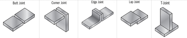
There are five fundamental types of joints used to bring two parts together for joining. These joint types are applicable not only to welding but also to other joining and fastening methods. The five joint types are defined as follows:
Butt joint: In this type of joint, the parts are aligned in the same plane and joined at their edges.
Corner joint: The parts form a right angle and are joined at the corner.
Lap joint: This joint involves two parts overlapping each other.
Tee joint: One part is positioned perpendicular to the other, resembling the shape of the letter "T."
Edge joint: The parts are parallel with at least one common edge, and the joint is made along this edge.
Types of Welds
Each of the aforementioned joints can be formed through welding. It is important to differentiate between the joint type and the method used to weld it—referred to as the weld type. The variations among weld types lie in their geometry (joint type) and the welding process employed.
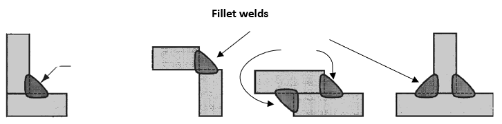
Fillet Weld
As seen below, a fillet weld is used to fill in the borders of plates formed by tee, lap, and corner joints. To create a cross-section that roughly resembles a right triangle, filler metal is employed. Since it only needs to employ the pieces' fundamental square edges for edge preparation, it is the most popular type of weld in arc and oxyfuel welding. It is possible for fillet welds to be single, double, continuous, or intermittent—that is, to be welded continuously along the joint's whole length or with unwelded gaps in between.
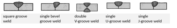
Groove Welds
Groove welds typically necessitate shaping the edges of the parts into a groove to enhance weld penetration. These grooves can be square, bevel, V, U, or J shapes, and they can be applied to either one or both sides, as depicted below. Filler metal, generally applied through arc or oxyfuel welding, fills the joint. Although this edge preparation requires more processing beyond the basic square edge, it is often done to strengthen the welded joint or when welding thicker parts. While groove welds are most commonly associated with butt joints, they are used in all joint types except lap joints.
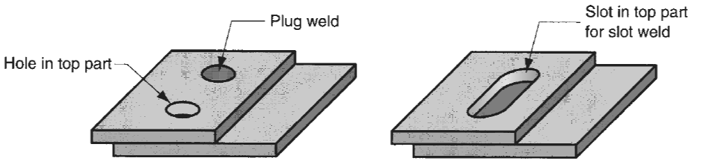
Plug welds and slot welds
Plug welds and slot welds are employed to join flat plates. This process involves creating one or more holes or slots in the top plate, which are then filled with filler metal to fuse the two pieces together.
Spot welds and seam welds are commonly used for lap joints. A spot weld involves a small, fused area between the surfaces of two sheets or plates, with multiple spot welds often necessary to join the parts effectively. This technique is most commonly associated with resistance welding. A seam weld is similar to a spot weld but consists of a continuous or near-continuous fused section between the two sheets or plates.
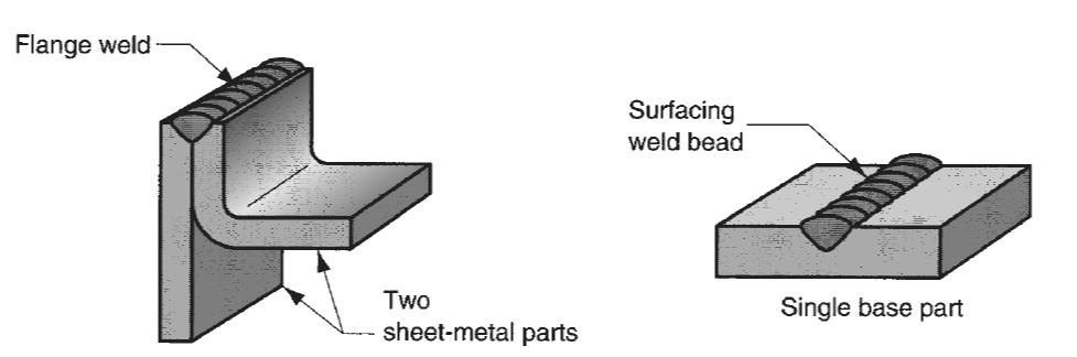
Flange welds
Flange welds and surfacing welds are depicted below. A flange weld is created on the edges of two or more parts, typically sheet metal or thin plate. On the other hand, a surfacing weld is not intended for joining parts but for depositing filler metal onto the surface of a base part using one or more weld beads. These weld beads can be applied in a series of overlapping parallel passes, covering large areas of the base part to increase its thickness or provide a protective surface coating.
Physics of Welding
High-density heat energy is given to the surfaces that need to fuse, resulting in localized melting of the base metals, to accomplish fusion. The heat must also be high enough to melt any filler metal that is utilized. The power density (W/mm² or Btu/sec-in²) is the unit of measurement used to describe heat density. It is inversely related to power density in determining the melting time. Low power densities cause melting to occur more slowly because heat disappears as soon as it is added, avoiding melting. Most metals can be melted during welding with a minimum power density of roughly 10 W/mm² (6 Btu/sec-in²). Melting time reduces as heat density rises. However, the metal vaporizes due to severe temperatures if the power density surpasses about 10⁵ W/mm³ (60,000 Btu/sec-in³). For welding to be effective, power density must be kept within a certain range. Welding rate and weldable region size are impacted by variations in welding methods.
Although oxygen fuel gas welding produces a lot of heat, it has a low density since it covers a big region. Oxyacetylene, the hottest OFW fuel, burns at about 3500°C (6300°F). By contrast, arc welding achieves local temperatures between 10,000°F and 12,000°F (or 5500°C to 6600°C) while delivering tremendous energy across a smaller area. High power densities are often more desirable since it is preferable from a metallurgical standpoint to melt metal with as little energy as possible.
Power density is calculated as the power entering the surface divided by the surface area:
PD = P/A
where PD is power density (W/mm² or Btu/sec-in²), P is power entering the surface (W or Btu/sec), and A is the surface area over which the energy is applied (mm² or in²). This calculation is complicated by factors such as the movement of the power source (e.g., the welding arc), which preheats the area ahead and postheats the area behind. Additionally, power density is not uniform across the affected surface, varying with area.
References
Groover, M.P., 2010. Fundamentals of Modern Manufacturing: Materials, Processes, and Systems. 4th ed. Hoboken, NJ: John Wiley & Sons, Inc.

&imgurl=https%3A%2F%2Fblogger.googleusercontent.com%2Fimg%2Fb%2FR29vZ2xl%2FAVvXsEhwhUMf34JBTz4q-ZS8p5Fz9R1g4NIjq5P1LZUq1R3TD90O4N65bJ-qnxT9z1Hb9rkSy_GLYQeJS5YaCUIJtE8Epzl7JkqK73D8r-F1skPfWIcbY5dzW7HbmN8TPTVMx86bgjo2BQ3E7MhM%2Fw1200-h630-p-k-no-nu%2Fdiffusion%2Bwelding.PNG&imgrefurl=https%3A%2F%2Fweld.theweldings.com%2F2020%2F11%2Fdiffusion-welding-bonding-process.html&docid=Hy-kUFCOL1DFoM&tbnid=qjvzqj2E1AixHM&vet=12ahUKEwjM_IWE9rmGAxV6UkEAHQAWAZ8QM3oECBcQAA..i&w=890&h=547&hcb=2&ved=2ahUKEwjM_IWE9rmGAxV6UkEAHQAWAZ8QM3oECBcQAA)