Friction stir welding (FSW) is a solid-state welding technique that forms the weld seam by manually stirring the metal to create friction heat and feeding a spinning tool along the joint line between two workpieces. This stirring or mixing action gives rise to the process's name. Conventional FRW generates friction heat from the parts themselves, whereas FSW generates it from a separate wear-resistant tool.
How Friction Stir Welding Works
In FSW, the rotating tool is stepped; it has a smaller probe that extends beneath its cylindrical shoulder. The shoulder creates a lot of frictional heat when it rubs against the top surfaces of the two pieces while welding. Concurrently, the probe—which is meant to make mechanical mixing easier—generates more heat by stirring the metal along the joint. Instead of melting the metal, this friction and mixing process softens it to a very malleable state.
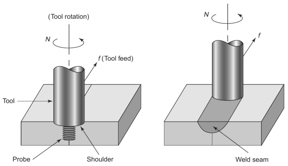
The leading surface of the rotating probe pushes the softened metal into the space behind it and around itself as the tool advances along the joint. The metal is forged into a seamless weld by this process. In order to ensure that the plasticized metal flows correctly around the probe, the shoulder is essential in constraining the material.
Fine, equiaxed recrystallized grains are formed through intense plastic deformation at high temperatures during the FSW process. Welds produced with this finely tuned microstructure have exceptional mechanical qualities. The robustness of the weld is enhanced by the intricate material movement around the pin made possible by the special tool geometry and the combination of translation and rotation.
Tool Geometry and Design
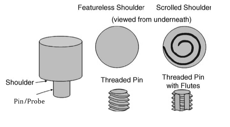
Tool geometry is essential to the development of the Friction Stir Welding (FSW) process. An FSW tool's design, which consists of a pin and a shoulder, is essential for welding traverse rate and material flow. The principal purposes of the tool are to facilitate material flow and to provide localized heating, as illustrated in Fig. below.
Heat is produced during the first plunge by friction between the pin and the workpiece as well as material deformation. Friction between the shoulder and the workpiece produces the majority of the heating component. Other design elements are less important for heating efficiency than the relative sizes of the pin and shoulder. Additionally, the shoulder helps with localized heating by confining the heated material.
The tool's ability to move and stir the material is its second vital role. The tool's design affects both the process loads and the weld's microstructure and properties' uniformity. Threaded cylindrical pins and a concave shoulder are usually used for these kinds of jobs.
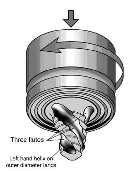
Tool geometry has developed to incorporate sophisticated features that improve material flow, mixing, and lower process loads as our understanding of material flow has grown. For example, TWI developed the Whorl and MX Triflute tools, which are depicted in Fig below, with pins fashioned like frustums. Compared to cylindrical pins with the same root diameter, these designs move a lot less material; roughly 60% and 70% less, respectively. The benefits of these tools include decreased welding power, easier plasticized material flow, and higher heat generation because of improved material-pin interface. They have welded aluminum plates up to 50 mm thick in one pass with success, and they have made even thicker welds in subsequent passes.
Traditional cylindrical threaded pins for lap welding frequently result in an excessive thinning of the top sheet, which reduces the bend characteristics. When fatigue is the main concern in an application, the weld interface width and the notch angle are crucial. To enhance the quality of lap welding, more recent pin geometries such as the A-skew and Flared-Trifute were created. These designs improve the forging and mixing activities at the weld interface, expand the welding zone, and raise the ratio of swept volume to static volume. They give substantially expanded welding areas, a reduction in upper plate thinning of more than a factor of four, and an improvement in welding speed of over 100% when compared to traditional pins, all with a 20% reduction in axial force.
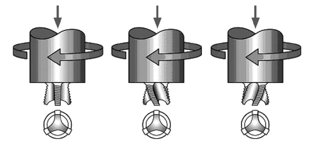
Flared-Triflute tools
These developments highlight the significance of tool geometry in Fluid Simulation. Particularly, the A-skew and Flared-Trifute pins raise the quality of the weld by reducing the notch angle at the weld interface, changing the flow path, and improving mixing actions.
Welding Parameters in Friction Stir Welding
Two factors are particularly important in Friction Stir Welding (FSW): tool traverse speed (v, mm/min) and tool rotation rate (ω, rpm). In order to finish the welding process, the tool's translation transfers the material that has been stirred along the joint line after its rotation has stirred and mixed the material around the rotating pin.
Intense material stirring and mixing are produced by higher tool rotation rates because of higher temperatures produced by greater friction heating. It is noteworthy, therefore, that the frictional interaction between the tool surface and the workpiece controls the heating process. It is therefore not necessarily expected that the heating will grow linearly with the tool rotation rate, as the coefficient of friction at the interface may vary.
Another important variable is the angle at which the tool or spindle tilts in relation to the workpiece surface. The threaded pin helps the tool shoulder move the stirred material efficiently when it is angled appropriately in the direction of the trailing material. For smooth tool shoulders and sound welds, the pin's insertion depth—sometimes called the goal depth—into the workpieces is also essential.
For effective material movement from the front to the back of the pin, an ideal insertion depth guarantees correct contact of the tool shoulder with the original workpiece surface. The weld may develop surface grooves or interior channels if the insertion depth is too shallow. On the other hand, if it is too deep, there could be a lot of flash, which would cause the weld to become noticeably concave and the welded plates to thin locally.
New developments, including "scrolled" tool shoulders, enable FSW without any tool tilt, which is very useful for joints with curves.
For some FSW processes, preheating or chilling may also be essential. It is possible that friction and stirring alone will not cause materials with high melting points, like steel and titanium, or high conductivity, like copper, to soften and plasticize around the revolving tool to the required extent. Preheating or adding more external heating sources can improve material flow and extend the process window in such circumstances. In contrast, cooling may be beneficial for materials with lower melting points, such as magnesium and aluminum, in order to stop strengthening precipitates from dissolving and significant growth of recrystallized grains in and around the stirring zone.
Joint Designs
Butt and lap joints are the most practical joint designs for Friction Stir Welding (FSW). Because of their versatility and ease of use, these designs are indispensable.
For a basic square butt junction, two identically sized plates or sheets are clamped firmly onto a backing plate. This keeps the faces of the adjoining joints from separating while welding. Significant forces are applied as the spinning tool plunges into the joint line; thus, it is very important to take particular care to maintain the plates aligned. The strong weld is produced when the tool shoulder traverses along the joint line after making contact with the plate surface. Butt joints are a common option for many welding applications because of their simplicity.
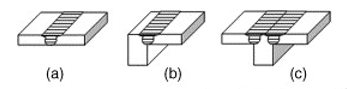
(a) square butt, (b) edge butt, (c) T butt
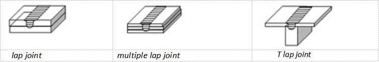
Another typical configuration is a lap joint, which is a backing plate clamped over two overlapping plates or sheets. The rotating tool connects the two plates by piercing vertically through the upper plate and into the lower plate and then moving in the correct direction. Applications where overlapping materials need to be securely linked benefit greatly from this technique.
FSW permits a range of alternative joint designs, including fillet joints, in addition to the fundamental butt and lap joints. These combinations, which combine aspects of butt and lap joints, are made to meet particular engineering requirements. For example, fillet joints (see Figure below) are employed when certain structural criteria need to be accommodated during the welding process.
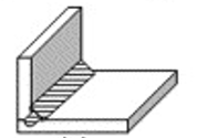
fillet joint
Advantages of FSW
For applications where safety and structural integrity are paramount, Friction Stir Welding (FSW) provides a multitude of benefits, including the creation of incredibly durable weld seams that can sustain elevated mechanical pressures. This process guarantees excellent dimensional stability with minimum distortion and produces connections that are media- and pressure-tight with little distortion. FSW produces a neat, fracture-free microstructure and maintains the characteristics of the alloy because it produces very little heat.
When it comes to the environment, FSW is exceptionally friendly because it does not require consumables like wires and gasses and does not require surface cleaning, grinding wastes, or shielding gas. It uses significantly less material and weighs less because its energy usage is only 2.5 percent of laser welding's. In the automotive, marine, and lightweight aircraft industries, this efficiency leads to lower fuel consumption.
FSW also produces a stronger, smoother weld seam than other welding techniques and reduces the number of fixed pieces that need to be replaced during the design and manufacturing process. This is achieved by slightly rotating the workpiece without using external forces.
Challenges and Limitations
There are various drawbacks to the friction stir welding (FSW) method. One major disadvantage is that when the tool is withdrawn, it leaves an exit hole that may be troublesome for some applications.
The pieces that are being welded also need to be clamped tightly, which complicates the operation.
Applications that depend on traditional equipment cannot use FSW because of the high initial investment and requirement for specialized equipment. Moreover, FSW requires a significant amount of downtime in between welds and is slower than other welding techniques.
Applications of Friction Stir Welding (FSW)
Many different industries employ friction stir welding (FSW), mostly for combining aluminum alloys of all grades that have been cast, rolled, or extruded. Depending on the alloy quality and machine capacity, this technique can weld aluminum alloy butt joints with thicknesses ranging from 0.3mm to 75mm in a single pass. FSW is useful for combining alloys like magnesium, titanium, copper, nickel, and steel in addition to aluminum. It can also be used to join plastics and metal matrix composites (MMC). It can even combine materials that aren't compatible, like steel and aluminum.
In the aerospace industry, FSW is perfect for producing thin alloy skins, fuel tanks, and airframes because of its high weld quality and geometric correctness. It is employed in the automotive industry for lightweight construction, which improves fuel efficiency. FSW is used in the shipbuilding and railroad industries to construct heavy-duty tanks, coaches, and railway carriages. FSW is also used in electronics, such as EV battery trays, demonstrating its adaptability to a range of uses.
References
Groover, M.P., 2010. Fundamentals of Modern Manufacturing: Materials, Processes, and Systems. 4th ed. Hoboken, NJ: John Wiley & Sons, Inc.