Runout in CNC machining refers to the deviation of a rotating component from its true centerline during operation. In practical shop terms, it is the reason a tool that looks perfectly straight on the bench cuts unevenly once the spindle starts turning. Even at the micron level, runout affects how the cutting edge engages the material, how chips form, and how forces are distributed during machining.

This article focuses on what runout really is, why it occurs in real machining systems, how to measure it correctly, and how it directly impacts quality, cost, and process reliability on the shop floor.
What Is Runout and Why Does it Occur
Runout describes the lack of perfect concentric rotation in a machining system. In simple terms, it means the rotating axis of the spindle, holder, or tool does not align exactly with the true centerline. As the spindle rotates, this misalignment causes the cutting edge to move slightly in and out instead of following a perfect circle. Even when the movement is measured in microns, the cutting process feels it immediately.
In CNC machining, runout rarely comes from a single defective part. It is usually the result of multiple small inaccuracies adding up across the system. Understanding what types of runouts exist and where they originate is the first step toward controlling them.
Radial runout vs axial runout
Runout is commonly divided into radial and axial components, and each affects machining in a different way.
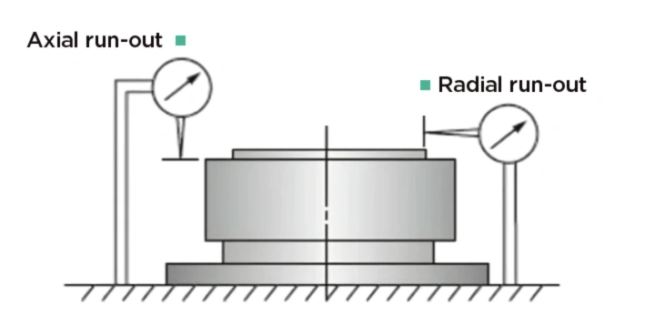
Radial runout refers to the side-to-side deviation of a rotating tool. This is the most common and damaging type in milling and drilling. When radial runout is present, one cutting edge removes more material than the others. This creates uneven chip load and accelerates wear on the dominant edge.
Axial runout refers to face wobble along the spindle axis. It is more relevant in operations and drilling. Axial runout affects flatness and perpendicularity rather than diameter. While it is often less discussed, it can still cause finish issues and inconsistent depths.
Both types can exist at the same time, and both should be evaluated when diagnosing accuracy problems.
Spindle runout vs tool runout
Spindle runout originates at the machine itself. It is measured at the spindle nose or inside the taper and reflects the condition of bearings, alignment, and internal geometry. Spindle runout sets the baseline accuracy for everything mounted to the machine.

Tool runout includes the combined effect of the toolholder, clamping system, and cutting tool. Even if the spindle is highly accurate, tool runout can still be excessive due to holder wear, poor clamping, or contamination at the interface.
In practice, tool runout is what most shops see and measure, but it is important to remember that it includes spindle contribution as well.
How does runout form through the stack-up
Runout in CNC machining is cumulative. Each interface introduces a small potential error.
Common contributors include:
- Spindle taper geometry
- Toolholder taper accuracy
- Collet or clamping system concentricity
- Tool shank straightness
- Pull the stud condition and seating
Individually, each error may be within tolerance. When combined, they can push total runout beyond acceptable limits. This stack-up effect explains why replacing only one component often fails to solve persistent runout issues.
Typical acceptable runout ranges
Acceptable runout depends on the operation, tool size, and material, but general guidelines are useful.
- High-precision milling often targets under 3 microns at the tool tip
- General production milling may tolerate 5 to 10 microns
- Drilling and reaming usually require tighter control due to edge sensitivity
It is important to note that these values are measured at the cutting diameter. Measuring closer to the holder can hide problems that become severe at longer tool lengths.
Effect of speed and tool length
Runout becomes more pronounced as spindle speed increases. Centrifugal forces amplify small geometric errors, causing greater tool deflection and vibration. This is why a setup that appears acceptable at low speed may fail at production RPM.
Tool length also plays a major role. Longer stick-out increases leverage, magnifying any existing misalignment. A few microns at the holder can translate into a significant deviation at the cutting edge.
This is especially critical in deep pocketing, mold work, and high-speed finishing.
Spindle Runout and Machine-Side Contributors
Spindle runout forms the foundation of accuracy in CNC machining. Every tool, holder, and cutting edge ultimately follows the rotational path defined by the spindle. When that path is imperfect, no downstream component can fully correct it. This is why spindle condition should always be evaluated before blaming toolholders or cutting tools for performance issues.
Machine-side contributors to runout tend to develop slowly over time. Because the changes are gradual, they often go unnoticed until surface finish degrades, tool life drops, or parts begin to drift out of tolerance. Understanding how these issues originate helps separate normal wear from serious mechanical problems.
Spindle bearing wear and preload issues
Spindle bearings are one of the most critical components influencing runout. Over time, bearing races wear and internal clearances change. As wear progresses, the spindle loses its ability to maintain a consistent rotational center.
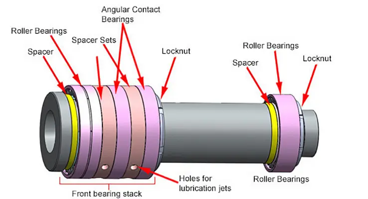
Spindle Cylindrical Roller Bearings Installation and Preload
Improper bearing preload is another common issue. If the preload is too low, the spindle can shift under cutting forces. If it is too high, excessive heat builds up and accelerates wear. Both conditions increase runout and reduce stability.
Typical symptoms linked to bearing problems include:
- Increasing runout as speed rises
- Audible noise at higher RPM
- Heat buildup during extended operation
Once bearing wear becomes significant, runout cannot be corrected through calibration or tooling changes. Mechanical repair becomes the only long-term solution.
Thermal growth and warm-up behavior
Thermal effects play a major role in spindle accuracy, especially in high-speed machining. As the spindle rotates, friction and motor heat cause it to expand. This thermal growth can shift the spindle centerline, temporarily increasing runout.
Cold machines often show higher runout during the first part of a shift. As temperatures stabilize, accuracy improves. Shops that skip warm-up cycles may see inconsistent results even when the machine is mechanically sound.
A controlled warm-up routine helps:
- Stabilize bearing preload
- Reduce thermal distortion
- Improve repeatability during measurement and cutting
Ignoring thermal behavior can lead to misdiagnosing a healthy spindle as defective.
Alignment errors and machine age
Spindle alignment relative to the machine axes is established during assembly and installation. Over years of operation, small shifts can occur due to vibration, heavy cutting, or foundation movement. These alignment errors introduce runout that appears tool-related but actually originates in the machine structure.
Older machines are more susceptible, particularly if they have experienced frequent heavy cuts or inadequate maintenance. While alignment errors are less common than bearing wear, they are harder to detect without proper testing equipment.
In many cases, alignment issues reveal themselves through:
- Directional accuracy problems
- Uneven tool wear across similar setups
- Inconsistent results between machines
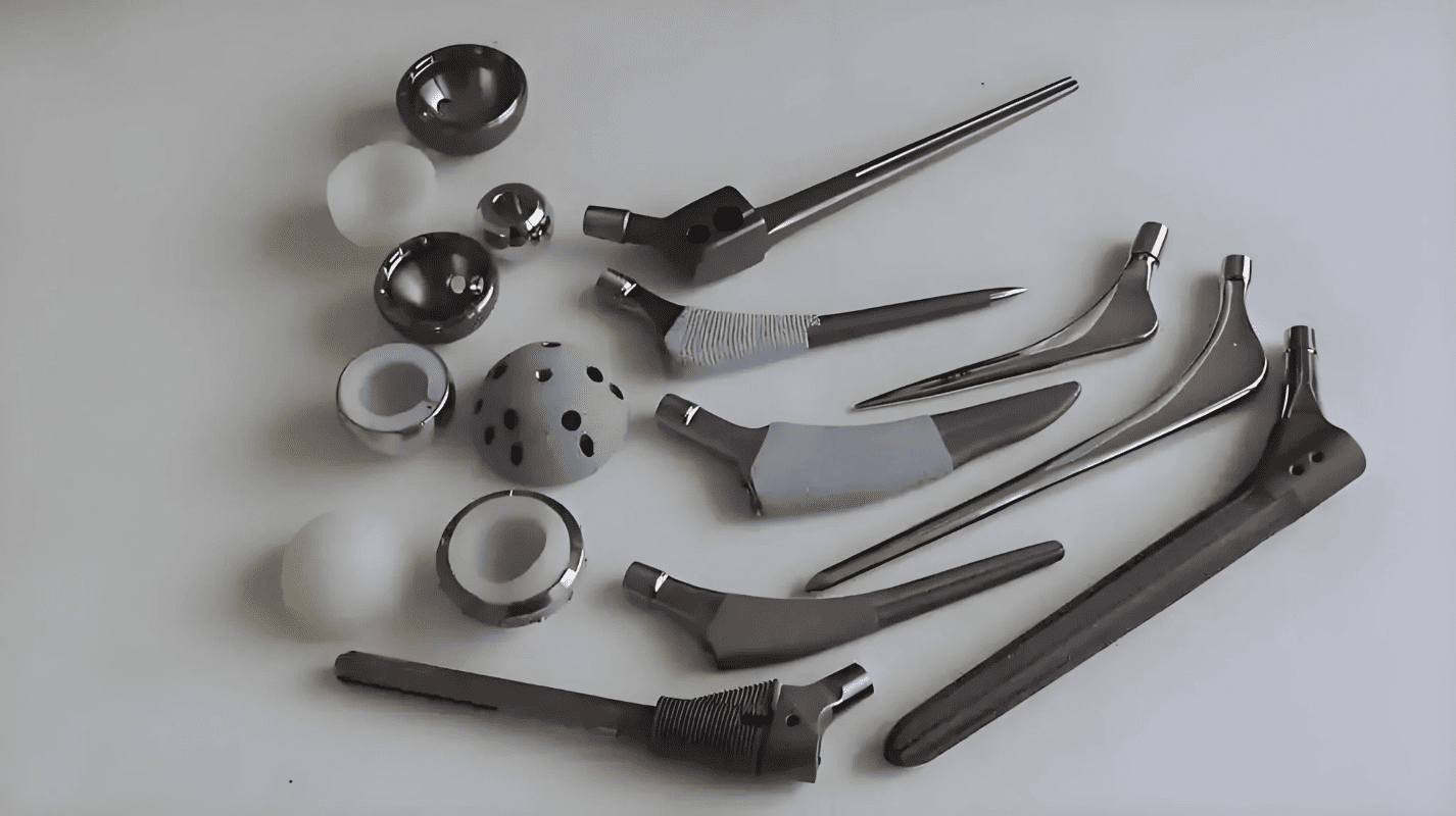
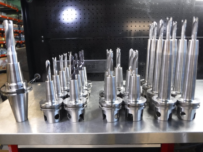
Toolholder, Taper, and Interface Problems
While spindle condition defines the upper limit of accuracy, the majority of excessive runout in daily production comes from the tooling side. Toolholders, tapers, and clamping interfaces are handled, changed, and reused constantly. Small mistakes at these interfaces accumulate quickly and often explain why runout varies from setup to setup on the same machine.
Unlike spindle issues, tooling-related runout is largely within the shop’s control. Understanding where these errors originate allows operators and engineers to prevent them rather than reacting after quality problems appear.
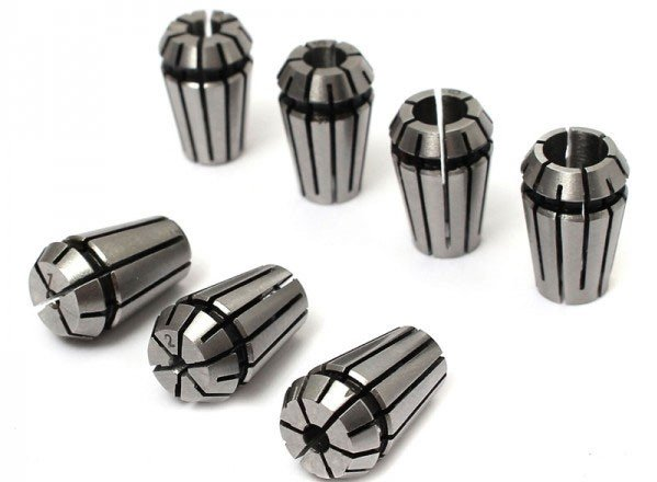
Toolholder manufacturing tolerances and wear
No toolholder is perfectly concentric. Even new holders leave the factory with a specified runout tolerance. Lower-cost holders typically allow higher deviation, while premium holders are manufactured and balanced to tighter limits.

Over time, toolholders wear. Repeated clamping, vibration, and tool changes gradually degrade internal surfaces. Collet seats lose concentricity, hydraulic chambers weaken, and taper surfaces develop contact marks.
Common sources of holder-related runout include:
- Worn collet seats
- Distorted hydraulic sleeves
- Micro damage from improper tightening
- Holder drops or mishandling
A holder that once performed well can slowly become a consistent source of error without obvious visual damage.
Comparison of common holder types
Different toolholder systems control runout in different ways. The choice of holder has a direct effect on concentricity, repeatability, vibration control, and long-term stability. While no holder can correct spindle error, the right system can significantly reduce additional runout introduced at the tool interface.
Shops often select holders based on availability or cost, but performance differences become clear when tolerances tighten or tool life becomes critical. Understanding how each holder type behaves helps align tooling decisions with process requirements.
| Toolholder type | Typical runout performance | Key advantages | Common limitations | Best use cases |
| Collet holder | Moderate, highly variable | Flexible, low cost, widely available | Sensitive to collet wear, dirt, and the tightening method | General milling, roughing, low-precision work |
| Hydraulic holder | Low and consistent | Good concentricity, vibration damping, and easy setup | Seal aging, higher cost than collets | Finishing, reaming, and precision milling |
| Shrink-fit holder | Very low and repeatable | Excellent concentricity, high rigidity | Requires heating equipment, sensitive to contamination | High-speed machining, tight tolerance finishing |
Collet holders remain common due to their versatility, but they are also the most sensitive to handling and cleanliness. Collet condition, torque consistency, and tool shank quality all influence final runout. A worn or mismatched collet can introduce more error than the holder body itself.
Hydraulic holders provide more consistent results because clamping pressure is applied uniformly around the tool shank. They also damp vibration, which improves surface finish. However, performance declines as internal seals age, making periodic inspection important.

Shrink-fit holders generally deliver the lowest runout when handled correctly. Their uniform clamping and rigid structure make them ideal for high-speed and finishing operations. Their main risk lies in poor taper hygiene and improper heating cycles, which can negate their advantages.
Selecting a holder should always consider required accuracy, tool length, cutting forces, and repeatability needs rather than cost alone.
Taper contamination and surface condition
The spindle-to-holder interface is one of the most overlooked sources of runout. Any contamination between tapers prevents full contact and shifts the holder off-center.
Typical contaminants include:
- Fine chips
- Dust and lint
- Oil films
- Fretting corrosion marks
Even a thin oil layer can act as a wedge, forcing the holder to seat unevenly. Fretting marks from micro movement reduce the effective contact area and worsen repeatability.
Routine cleaning of both spindle and holder tapers is one of the most effective runout control practices in any shop.
Clamping errors and pull stud problems
Improper clamping introduces both runout and instability. If a pull stud is worn, damaged, or incorrectly specified, the holder may not seat consistently. This affects both concentricity and retention force.
Over-tightening collets can also distort the holder or collet, increasing runout rather than reducing it. Under-tightening allows micro movement during cutting, which worsens wear and finish.
Clamping systems should be checked for:
- Correct pull stud type and length
- Consistent drawbar force
- Proper torque procedures
Ignoring these details often leads to chasing runout that appears random but is actually repeatable.
Measuring Runout Correctly in CNC Machining
Measuring runout correctly is essential before making any decisions about machine condition, tooling quality, or process capability. Many runout problems are misdiagnosed due to poor measurement technique rather than actual mechanical issues. A few microns of error in setup or interpretation can easily lead to false conclusions and unnecessary corrective actions.
Runout measurement should be treated as a controlled inspection process, not a quick check. Consistency in tools, locations, and procedures is what turns raw readings into reliable data.
Measurement tools and their applications
Several tools are commonly used to measure runout in CNC machining, each with its own strengths and limitations. Selecting the right method depends on what part of the system is being evaluated.
Dial indicators are the most widely used option on the shop floor. They are cost-effective and suitable for routine checks when properly mounted and zeroed. However, their accuracy depends heavily on operator technique and indicator quality.
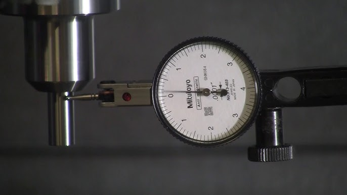
Measuring Total Runout Using a Dial Gauge
Test bars provide a known straight reference and are useful for isolating spindle runout from tooling effects. They are typically used during machine qualification or after service work.
Laser measurement systems offer high resolution and repeatability. They are ideal for machine diagnostics and documentation, but are less practical for daily use due to cost and setup time.
Where runout should be measured
The location of measurement determines what the reading actually represents. Measuring at only one point can hide the true source of error.
Common measurement points include:
- Spindle nose or taper to assess machine condition
- Toolholder taper to check seating and cleanliness
- Tool shank near the holder face
- Tool cutting diameter for process relevance
Measuring closer to the cutting edge provides the most meaningful data for machining performance. Measuring only at the holder often underestimates the real runout seen during cutting.
Proper measurement procedure
Accurate runout measurement requires a repeatable process. Skipping steps or rushing setup introduces more errors than the machine itself.
Key steps include:
- Thoroughly clean all contact surfaces
- Secure the indicator rigidly to avoid vibration
- Rotate the spindle slowly by hand
- Record maximum and minimum readings consistently
The spindle should never be rotated under power during measurement. Even low RPM introduces vibration and bearing movement that distort readings.
Common measurement mistakes
Many reported runout issues are caused by technique rather than hardware. Understanding common errors helps prevent misinterpretation.
Frequent mistakes include:
- Measuring on rough or damaged surfaces
- Applying a side load with the indicator tip
- Using worn or low-resolution indicators
- Comparing readings taken at different tool lengths
Another common issue is ignoring temperature. Measurements taken on a cold machine often differ from those taken after warm-up, leading to inconsistent conclusions.
Interpreting micron-level readings
Micron-level values must be evaluated in context. A reading that looks acceptable at one location may be problematic at another.
For example, 3 microns at the holder face may translate into significantly more at the cutting edge on a long tool. Conversely, a slightly higher spindle reading may be acceptable for roughing operations but not for finishing.
Trend tracking is often more valuable than a single measurement. Gradual increases over time usually indicate wear, while sudden changes suggest damage or contamination.
Inspection frequency and documentation
Regular inspection prevents small problems from becoming major failures. Runout checks should be scheduled based on machine usage, precision requirements, and crash history.
Effective documentation practices include:
- Recording measurement location and tool length
- Noting the machine temperature state
- Tracking changes over time
Documented data allows informed decisions rather than reactive troubleshooting.
Quality Impact: Surface Finish, Tool Life, and Scrap
Runout is often discussed as a measurement problem, but its real impact is seen in production results. When a tool does not rotate concentrically, the cutting process becomes uneven and unpredictable. This directly affects surface finish, tool life, dimensional accuracy, and overall process stability. In many cases, shops compensate by slowing feeds, reducing depths of cut, or simply accepting higher scrap rates without identifying runout as the root cause.
Understanding how runout translates into quality loss helps justify tighter control and more disciplined inspection practices.
Uneven chip load and cutting edge imbalance
Runout causes one cutting edge to engage the material more aggressively than the others. This uneven chip load concentrates cutting forces on a single edge rather than distributing them evenly.
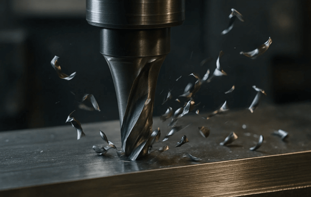
As a result:
- One edge wears rapidly while others remain underutilized
- Chip formation becomes inconsistent
- Cutting forces fluctuate during rotation
This imbalance increases vibration and reduces process predictability. In multi-flute tools, the problem compounds as the tool diameter increases.
Accelerated tool wear and premature failure
Because one cutting edge carries a disproportionate load, wear progresses unevenly. The dominant edge dulls quickly, increasing cutting forces and heat generation.
Over time, this leads to:
- Edge chipping and microfracture
- Coating breakdown
- Sudden tool breakage under normal cutting conditions
Tools often fail well before their expected life, even though feeds and speeds appear conservative. Without addressing runout, replacing tools alone does not solve the problem.
Surface finish degradation and chatter
Surface finish is one of the earliest indicators of excessive runout. As the cutting edge oscillates, it leaves behind irregular tool marks rather than a uniform pattern.
Typical surface quality issues include:
- Visible waviness on machined faces
- Inconsistent scallop patterns
- Chatter marks that worsen at higher speeds
Even small amounts of runout can degrade the finish in high-speed or finishing operations. Polishing or secondary operations may be required to compensate, increasing cycle time and cost.
Dimensional inconsistency and tolerance drift
Runout affects dimensional accuracy by altering the effective cutting diameter. As the dominant edge wears, the tool cuts progressively smaller or larger depending on the operation.
This results in:
- Gradual size drift during long production runs
- Increased variation between parts
- Difficulty holding tight tolerances consistently
Operators may adjust offsets frequently without realizing the underlying cause is tool runout rather than material variation or tool wear alone.
Scrap, rework, and hidden production losses
The financial impact of runout extends beyond visible defects. Scrap parts, rework, and lost machine time quietly erode profitability.
Small micron-level deviations can lead to:
- Out-of-tolerance features are late in the process
- Rejected parts after significant value has been added
- Reduced confidence in unattended machining
Because these losses are distributed across tooling, labor, and quality departments, runout is often underestimated as a cost driver.
Conclusion
Runout control is a fundamental requirement for consistent and predictable CNC machining. Even small deviations influence how cutting forces are distributed, how tools wear, and how surfaces are formed. When runout is ignored, shops often respond with slower feeds, frequent offset changes, or premature tool replacement, none of which address the underlying issue. Treating runout as a system-level concern allows problems to be identified early and corrected at their source.
Prevention is far more effective than correction. Clean interfaces, appropriate toolholder selection, controlled tool length, and regular inspection practices reduce variability before it reaches the cutting edge. Most importantly, recognizing that microns have real consequences helps shift runout from an abstract measurement to a practical quality driver that directly affects performance, cost, and long-term reliability.