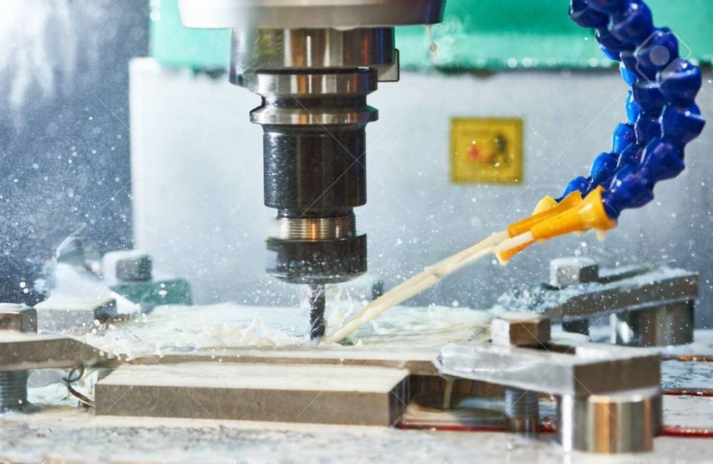
Aluminum and its alloys have numerous applications in various sectors such as, in transportation, general engineering, electrical, structural and construction areas. It is also useful in the production of domestic products, and for packaging in the chemical and food sectors. Aluminum as compared to other metals, has a low hardness and a high thermal expansion value. This makes the production of aluminum precision components vulnerable to product deformation.
A variety of factors contribute to the deformation of aluminum alloy precision components. These factors include, material, manufacturing environment, part shape, and cutting fluid performance. The following are ways for reducing distortion in aluminum alloy components during CNC machining:
1. Reduce the internal stress of the aluminum material
Stress is defined as the measurement of internal forces induced by particles within a material exerting pressure on one another. Strain is a measure of stress, that reflects the degree of deformation induced by a material's internal tension. Strain in a material is induced by either internal or external forces. External forces apply stress to the mass of the material, (e.g., gravity) or to its surface (e.g., contact forces, external pressure, friction).
Residual stress is a common form of stress that is commonly left over from the manufacturing process. Residual stress causes the highest distortion in thin components.
Some of the most common methods for releasing tension in aluminum are:
- Making a series of mild cuts as the component approaches completed size. Stress relieving the part between rough and finish machining can also reduce or eliminate distortion that is caused by machining stresses
- Vibrational stress release (VSR) is also another common way for stress relief. VSR involves bending the metal with enough amplitude to combine the generated and residual stress. Plastic flow occurs as a result, resulting in tension alleviation. To optimize the amount of stress alleviation, VSR targets the metal's resonance frequency. This non-thermal stress relief method is used in metalworking to improve dimensional stability and mechanical integrity. It is used, particularly for cast, forged, or welded aluminum. Precision components with exceptionally tight dimensional or geometric tolerances are frequently employed with VSR.
- Cryogenics is another method of stress relief that reduces residual tension together with improving wear and corrosion resistance. An aluminum item is placed in a specific tank and subjected to liquid nitrogen. Depending on the kind of alloy and thickness, the temperature drops to as low as -300°F, and the metal is left there for a specific length of time. The temperature is then gradually increased to room temperature. The cryogenic method is an option to more prevalent techniques of heat treatment. Aluminum treated in this way has lesser chances of deforming and is stronger and more durable. Other advantages include less stress cracking, a lower coefficient of friction, and increased impact resistance. Parts that are handled in this way are more amenable to machining and redressing, and completed parts have a longer lifespan.
- Heat treatment methods for aluminum
- Annealing. Aluminum alloys are frequently work hardened early in the manufacturing cycle. The deliberate plastic deformation of a workpiece is often described as strain hardening. Strain hardening modify the crystalline structure inside the metal, and is subsequently reset by annealing. The metal is heated for up to three hours, to temperatures ranging from 570°F to 770°F.This reduces the tension caused by the work hardening process and aid in the resolution of warping and other difficulties.
- Solution heat treatment is another type of heat treatment. The metal is immersed in a solution at a high temperature (between 825°F and 980°F) and then quenched to fast cool the substance. This trap dissolved components, which then precipitate out, resulting in an age hardening effect. The metal is easy to work with just after quenching, but it hardens with time and becomes increasingly difficult to work with.
2. Enhance the tool's cutting efficiency.
It is vital to pick the correct cutting tools to reduce component machining deformation. Cutting tool material and geometric factors have significant impact on the cutting force and heat.
Geometric factors influencing tool efficiency are:
i. Front Angle
The front angle must be carefully set to preserve the blade's strength; otherwise, the sharp edges would deteriorate. The rake angle should be properly large in order to preserve the edge's strength. On the one hand, it can be used to sharpen edges. It also can, on the other hand, reduce cutting distortion, ensure smooth chip removal, and then reduce cutting force and temperature. The use of negative rake angle tools is not advised.
ii. Rear Angle
The rear angle has a significant effect on side wear and processing quality. When determining the rear angle, the cutting thickness is an essential factor to consider. The tool used must have appropriate heat dissipation conditions, therefore a lower relief angle should be used. This is because of the high feed rate, strong cutting load, and high heat production in rough milling. Sharp edges are necessary in fine milling to decrease friction between the side and the machined surface as well as elastic deformation. Consequently, a wider relief angle should be chosen.
iii. Helix Angle
The helix angle needs to be as large as appropriate to provide smooth milling and lower milling force.
iv. Principal deviation angle
A proper lowering of the primary deviation angle can enhance heat dissipation conditions and lower the processing area's average temperature.
3. Workpiece Clamping Techniques Should Be Improved
In certain thin-walled aluminum components with low stiffness, the clamping methods described below can be utilized to decrease deformation:
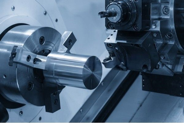
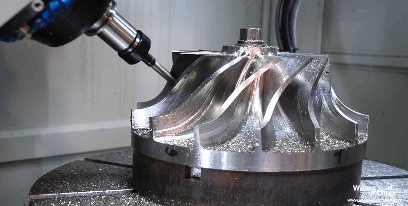
Three-jaw self-centering chuck
- If a three-jaw self-centering chuck or spring chuck is used to clamp thin-wall CNC machining bushing components from the radial direction, the workpiece will undoubtedly distort once it is released after processing.
A method of pressing the axial end face with good stiffness should be adopted. A threaded mandrel is manufactured to find the part's inner hole based on the position of the part's inner hole. It should be inserted into the part's inner hole. The end face is compressed with the cover plate, and the nut is tightened rearward, with the unclamping deformation may be prevented while machining the outside circle, and machining precision can be achieved.
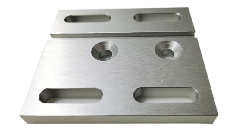
- Unless processing thin-walled plate components, it is advisable to employ vacuum suction cups to achieve a more uniformly distributed clamping force, and then process with a smaller cutting amount to avoid part deformation.
Alternatively, filling procedures can be employed. To increase the process stiffness of thin-walled workpieces, media can be introduced into the workpiece to decrease workpiece deformation during clamping and cutting. For instance, one can pour a urea melt containing 3% to 6% potassium nitrate into the workpiece. After processing, submerge the workpiece in water or alcohol, then dissolve and drain away the filler.
4. Improve the Design of Cutting Tools
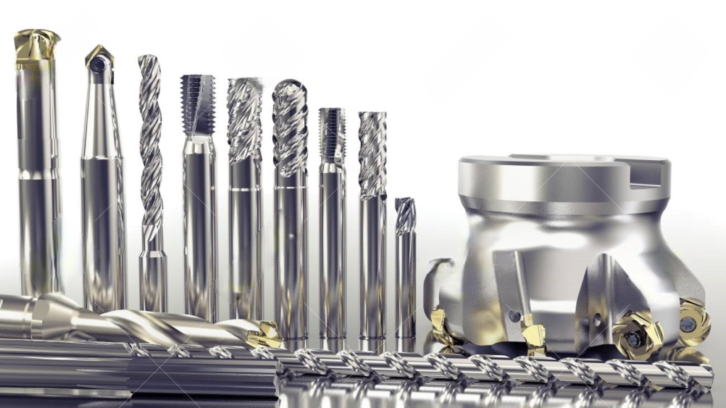
Cutting tools
- Reduce the number of milling cutter teeth while increasing chip holding space.
A bigger chip area is necessary due to the high plasticity of aluminum material and the high cutting deformation during processing.
Thus, the radius of the bottom of the chip flute should be bigger, but the number of milling cutter teeth should be smaller. The radius of the tank's bottom should be increased, while the number of milling cutter teeth is decreased. To minimize distortion of aluminum alloy thin-walled components owing to chip blockage, two cutting teeth are used in a milling cutter of 20 mm or less, and three cutting teeth are used in a milling cutter of 30 to 60 mm.
- Finely sharpen the teeth.
The cutting edge has a roughness of Ra=0.4um or less. Prior to utilizing a fresh cutting tool, a few gentle rubbings with fine asphalt should be done on the front and rear of the cutter teeth to remove any burrs or minor serrated markings that may have remained after grinding the tool teeth. Cutting heat is lowered, and cutting distortion is minimized because of this method.
- Control the tool's wear standard as strictly as possible.
The surface roughness of the workpiece rises as the tool wears, together with the cutting temperature and deformation of the workpiece. As a result, in addition to selecting tool materials with strong wear resistance, the tool's wear standard should not be larger than 0.2mm, otherwise chip edges are easily produced. To avoid distortion, the temperature of the treated workpiece should not exceed 100°C while cutting using CNC milling or CNC turning.
5. Organize The Production Process Appropriately
Vibration occurs frequently during milling in high-speed cutting because of the wide machining allowance and intermittent cutting. This affect machining accuracy and surface roughness. As a result, the CNC high-speed cutting process is broadly classified as follows: rough machining-semi-finish machining-clear corner machining-finishing. It may be essential to undertake a second semi-finishing step before finishing for items that require a high level of precision. The pieces are allowed to cool naturally after rough machining to reduce internal tension and deformation.
After rough machining, the residual margin should be more than the distortion, generally 1-2 mm. The part's surface should be homogeneous throughout finishing.
In general, keeping the tool steady during the finishing process with 0.2-0.5mm is the best technique to reduce cutting deformation, achieve high surface processing quality, and maintain product correctness.
Aside from the reasons stated above, the operation technique is also critical in real operation, and the right operation method may significantly minimize the bending of aluminum alloy components.
6. Symmetrical Machining
To improve heat dissipation and prevent thermal deformation in cnc aluminum machining components with high machining allowances, extreme heat concentration must be avoided. Symmetric processing is a technique that can be used for doing this.
Consider the case of a 90mm thick metal plate that needs to be reduced down to 60mm thickness. Even though each surface is treated to the final size and the continuous machining allowance is considerable, if the milling side is instantaneously transferred to the other side, heat concentration will be a problem, and the alloy plate's flatness will only be 5 mm
However, if the symmetrical processing technique is performed on both sides, every surface may be treated at least twice more until the ultimate size is attained, which is favorable to heat dissipation and flatness can be regulated at 0.3 mm.
7. Select the Suitable Cutting Parameters
Cutting force and the resulting cutting heat can be decreased by using the right cutting parameters. When the cutting parameters are larger than usual in the mechanical processing process, it will result in excessive cutting force. Excessive cutting force may easily cause deformation of the components, as well as influencing the stiffness of the spindle and the tool's longevity.
The amount of back cutting depth has the greatest impact on cutting force of all the cutting parameters. Lowering the number of cutting tools is essential for ensuring that pieces do not distort. However, this causes reduction in processing efficiency. This challenge can be solved with numerical control machining's high-speed milling.
Machining can lower cutting force and ensure processing efficiency by reducing back cutting depth, increasing feed, and raising machine speed.

8. Take Note of The Cutting Tool Walking Path Sequence
Cutting sequences for rough machining and finishing should be distinct.
Rough machining prioritizes machining efficiency and the goal of removal rate per unit time. In most cases, reverse milling can be used. (A reversing mill is a type of rolling mill in which the workpiece is run between a pair of rolls both forward and backward. The reversing mill gets its name from the fact that the steel goes back and forth between the rollers, gradually lowering the thickness with each pass)
That is, the excess material on the surface of the blank is removed as quickly and as efficiently as possible, and the geometric contour required for finishing is essentially generated.
When it comes to finishing, the emphasis should be on precision and quality, and down milling should be used. The cutting thickness of the cutter teeth steadily drops from maximum to zero during down milling, hence the degree of work hardening is considerably reduced, as is the degree of component deformation.
9. Two-times compression of thin-walled parts
Clamping force causes deformation while processing cnc aluminum machining components. Before the final size is achieved, the pressed piece should be released and the pressure should be reduced to recover it to its initial form. Then the second pressure should be applied to lessen the deformation of the workpiece produced by clamping.
The support surface is the optimal place for the second pressing point, and the clamping force should be applied in the direction of maximal stiffness.
The compression force should be adequate to keep the workpiece from loosening if everything is in order.
This procedure necessitates the use of skilled operators, but it may assure that the processed cnc aluminum machining components are deformed as little as possible.
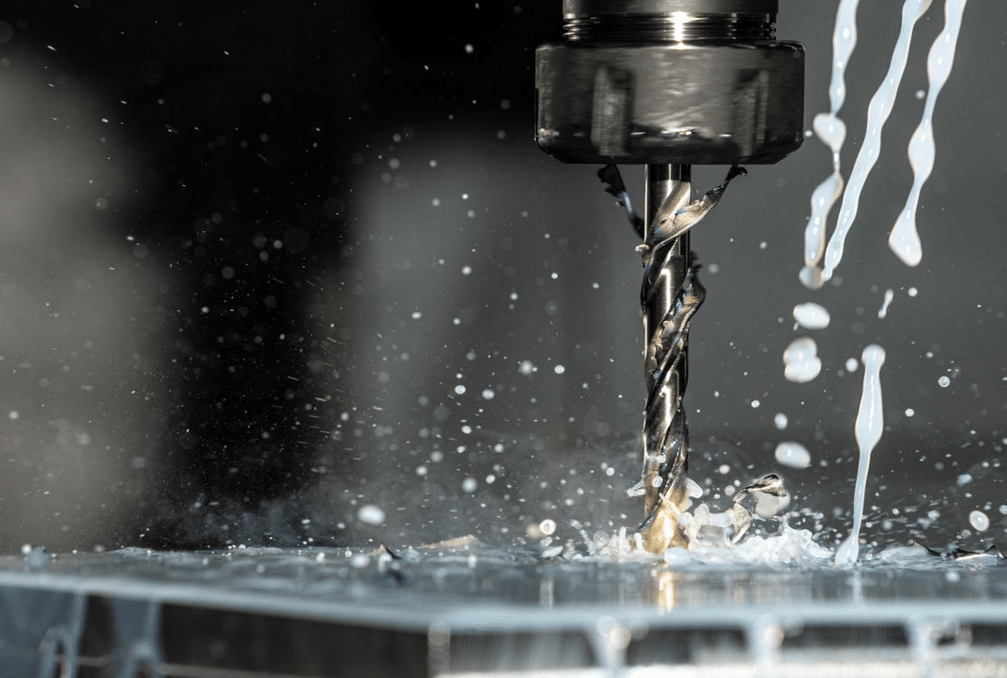
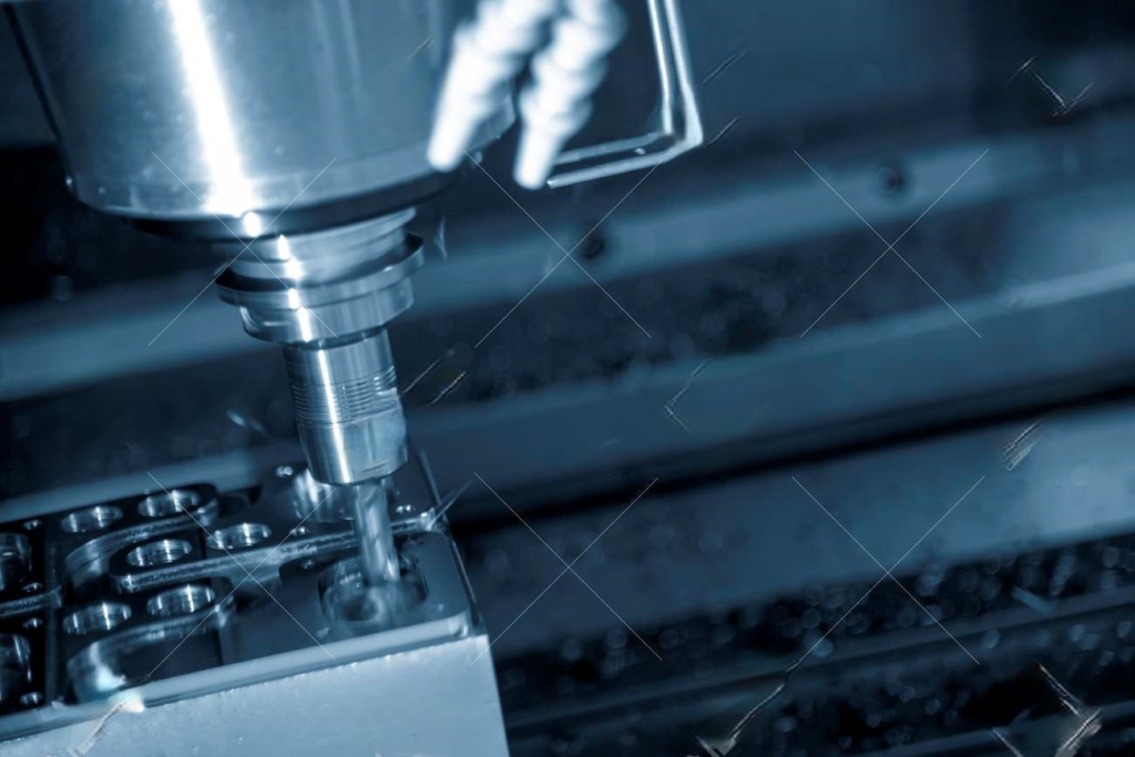
10. Drilling And Milling
Processing cavities in cnc aluminum machining components has its own set of challenges. Whenever the milling cutter is used directly on the component, the cutting chips will not be smooth due to the milling cutter's lack of fragmentation space. This causes a huge amount of cutting heat to build up, which expands and deforms the cnc aluminum machining parts, , as well as causing damage to the component or tool.
Drilling first and then milling is the best technique to handle this problem.
This entails drilling a hole with a tool no smaller than the milling cutter before placing the milling cutter into the hole to begin milling.
11. Use special aluminum alloy cutting oil
Special cutting oil is a type of fluid that must be used throughout the CNC cutting process for lubrication, cooling, cleaning.
Several types of coolants can be utilized while machining aluminum.
Water soluble mixes can be utilized successfully to disperse heat during rough machining where stock removal is sufficient to create heat.
Straight mineral seal oil, a 50–50 blend of mineral seal oil and kerosene, a mixture of 10% lard oil and 90% kerosene, and a 100-second mineral oil cut back with mineral seal oil or kerosene are some other oils that may be advised.
New cutting oils typically use sulfurized extreme pressure anti-wear additives as their core components. This is due to the continuous improvement of high-speed cutting tools, equipment, and processes. This helps to protect tools in the ultra-high-speed cutting process, improve process accuracy and cutting efficiency.