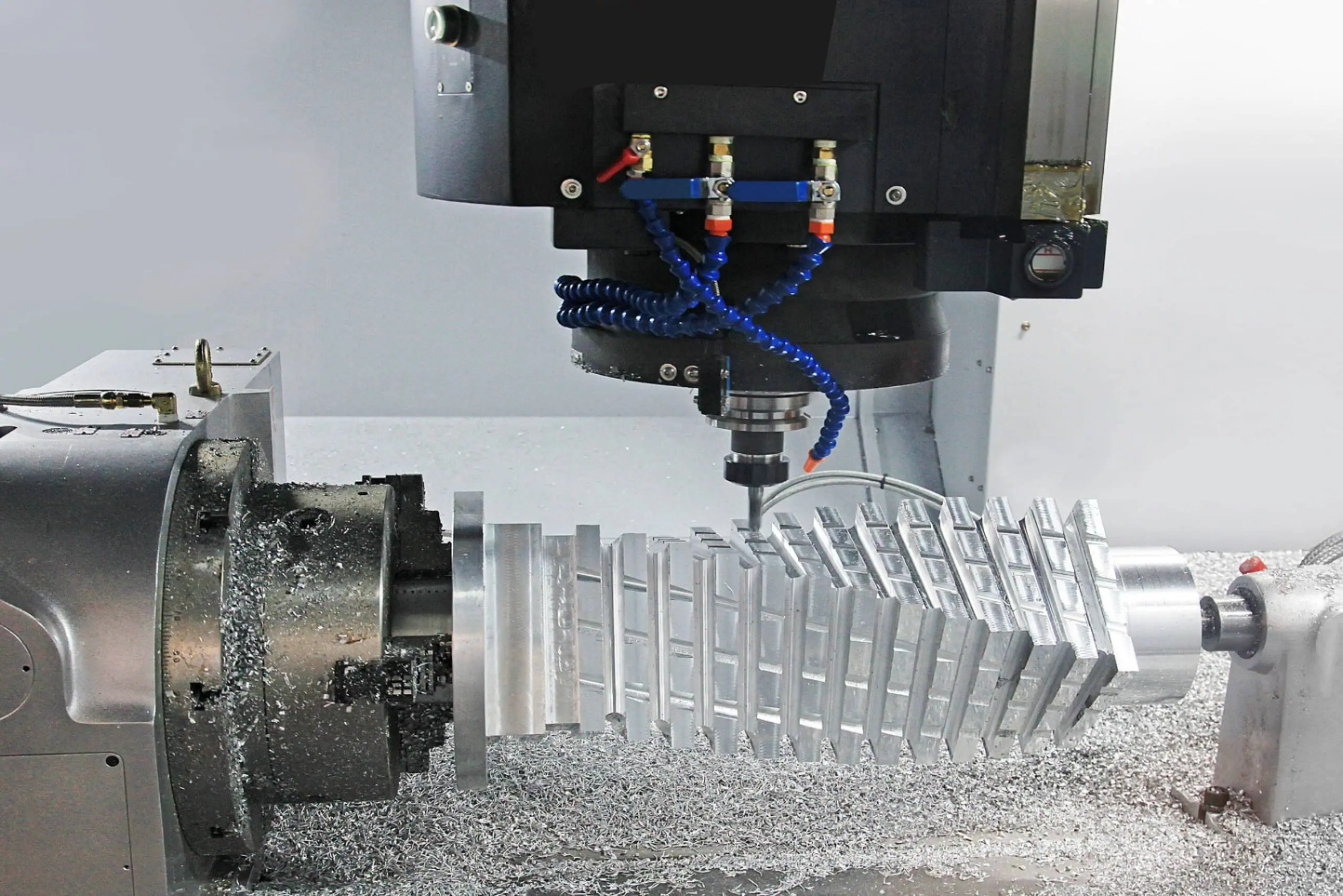
In mechanical engineering, shafts are among the most fundamental power-transmitting components found in virtually every rotating machine. Despite appearing straightforward in concept, production shafts are rarely uniform cylinders. They are precision-engineered with multiple diameter zones, each serving a distinct mechanical function: seating bearings, mounting gears, accommodating seals, or providing clearance for adjacent components. This geometric complexity is not incidental; it is a direct response to the functional demands placed on rotating assemblies in real-world operating conditions.
CNC step turning is the primary machining method used to produce these multi-diameter forms with the accuracy and repeatability that modern engineering requires. Through controlled, sequential material removal along the workpiece axis, the process creates precise diameter transitions, shoulder faces, and surface finishes that meet tight dimensional tolerances. As shaft designs grow more complex and production volumes increase, the ability to consistently machine stepped profiles in a single setup has made CNC step turning an indispensable operation in precision shaft manufacturing.
Understanding Multi-Diameter Shaft Geometry
A stepped shaft is defined by its series of concentric cylindrical sections, each machined to a specific diameter, length, and surface condition. Unlike a plain shaft, where a single diameter runs the full length, a stepped shaft distributes mechanical functions across discrete zones. Understanding the geometry of these zones is a prerequisite for both design and machining, as each dimensional feature carries a specific engineering purpose.
What Defines a Stepped Shaft
A stepped shaft consists of two or more coaxial cylindrical segments of differing diameters, connected by transverse faces known as shoulders. The diameter of each step is determined by the component it interfaces with, whether a rolling element bearing, a gear bore, a coupling hub, or a seal housing. The length of each step is governed by the axial space occupied by the mating component. Together, these dimensions define the shaft's functional envelope and directly drive the machining sequence.
Functional Role of Each Diameter Section
Each diameter zone on a stepped shaft is designed to fulfill a specific role within the assembly. Common functional sections include:
- Bearing seats: Machined to tight tolerance fits (typically h6 or k5 in ISO system) to ensure proper load transfer and prevent fretting. A deviation of even a few microns in this zone can compromise bearing life significantly.
- Gear or pulley mounting zones: Require precise diameters combined with keyways or splines to transmit torque without slip or fretting corrosion.
- Seal running surfaces: Demand fine surface finishes, typically Ra 0.4 to 0.8 micrometers, to prevent leakage while minimizing seal wear.
- Clearance sections: Intentionally reduced diameters that allow components to pass over the shaft during assembly without interference.
This zonal differentiation means that a single shaft may require four or five distinct diameter tolerances, each held to different classes of fit depending on function. [1]
Fundamentals of CNC Step Turning
CNC step turning is the foundational lathe operation used to produce the segmented diameter profile of a stepped shaft. While the concept of turning stepped diameters predates CNC technology, the introduction of computer-controlled toolpaths transformed what was once a highly skill-dependent manual operation into a repeatable, programmable process capable of holding tolerances in the micron range. Understanding the mechanics behind the operation is essential for anyone involved in shaft design, process planning, or CNC programming.
Basic Definition of the Operation
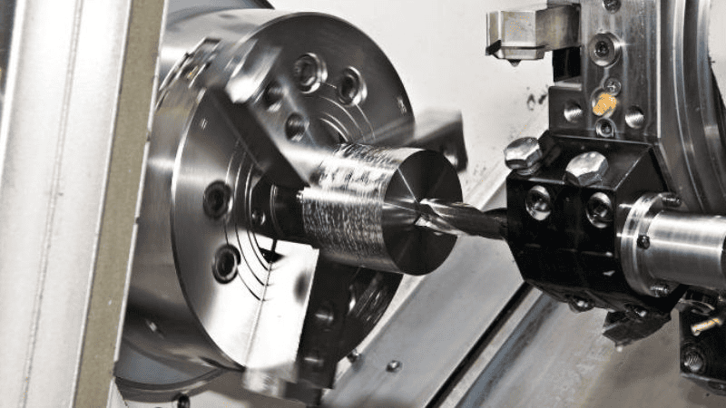
Step turning is a turning operation in which a cutting tool removes material from a cylindrical workpiece at different axial positions and radial depths to produce a series of concentric steps. Each step corresponds to a target diameter, and the transitions between steps form the shoulder faces. The operation is performed on a CNC lathe, where the tool follows a programmed path along the Z-axis (axial) and X-axis (radial) to generate each diameter and its associated shoulder in sequence.
Material Removal Along the Z-Axis in Segmented Stages
Material removal in step turning is organized into axial segments. Rather than machining the entire shaft length in a single pass, the process divides the workpiece into zones corresponding to each stepped diameter. Within each zone, the tool makes successive radial cuts to reduce the diameter from stock size to the target dimension. This segmented approach allows the programmer to assign different cutting parameters, such as feed rate, depth of cut, and spindle speed, to each zone based on its diameter, length, and required surface finish. For example, a long bearing seat on a gearbox shaft may require multiple roughing passes followed by a dedicated finishing pass, while a short clearance groove requires only a single cut. [2]
Formation of Diameter Transitions and Shoulder Faces
The shoulder face formed at each diameter transition is not merely a byproduct of the step turning process. It is a precision surface that must meet specific squareness and positional tolerances. When the cutting tool completes a cylindrical pass at a given diameter and reaches the programmed Z-axis shoulder position, it transitions radially to begin cutting the next step. The resulting perpendicular face must be:
- Square to the shaft axis, to ensure axially loaded components seat correctly without introducing moment loads.
- Positioned accurately in the Z-axis to maintain correct spacing between components such as bearings and retaining rings.
- Free of burrs or tool marks, to avoid interference with mating components during assembly.
The geometry of the cutting insert, particularly its nose radius and lead angle, directly influences the quality of the shoulder face produced. A smaller nose radius improves shoulder definition but reduces insert strength, requiring a balance based on material and cutting conditions.
How CNC Programming Controls Step-by-Step Geometry Creation
CNC programming is the mechanism that translates the shaft drawing into machine motion. In step turning, this typically involves:
- Absolute coordinate positioning, where each shoulder Z-position and step diameter is defined as a fixed coordinate rather than an incremental offset, reduces the accumulation of positional errors across multiple steps.
- Canned roughing cycles, such as G71 in FANUC-based controls, automate the multi-pass material removal down to a defined profile, allowing the programmer to specify depth of cut, feed rate, and finishing allowance in a single block.
- Finishing cycles, such as G70, which follow the roughing cycle and execute a single clean pass along the programmed profile to achieve final dimensions and surface finish.
- Spindle speed control with constant surface speed (CSS), which adjusts the RPM as the tool moves across different diameters to maintain a consistent cutting speed, improving surface finish uniformity across all steps.
This level of programmatic control is what distinguishes CNC step turning from conventional manual turning and is the primary reason it dominates precision shaft production in modern manufacturing environments.
Typical Step Turning Workflow in CNC Machining
The step turning process follows a structured sequence from raw workpiece to finished shaft. Each stage of the workflow builds on the previous one, and errors introduced early, whether in setup, rough machining, or shoulder formation, propagate through to the final part. A disciplined approach to each phase is therefore not optional; it is a fundamental requirement for producing shafts that meet dimensional and functional specifications consistently.
Workpiece Setup and Alignment
Proper workpiece setup is the single most critical factor in achieving concentricity across all diameter steps. If the shaft is not rotating on its true geometric axis from the start, no amount of precision programming will compensate for the resulting runout.
Chucking methods vs. between-centers setup:
- Three-jaw chuck mounting is common for shorter shafts and production environments where cycle time is a priority. However, chuck jaw wear and workpiece surface condition can introduce runout errors of several microns, which must be checked and corrected before cutting begins.
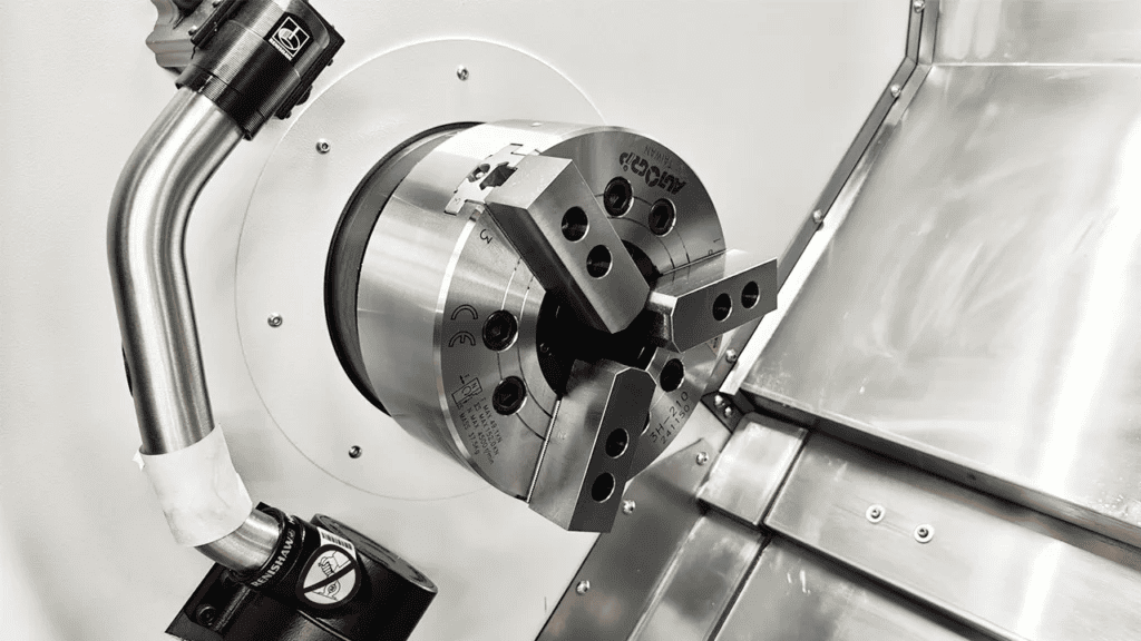
- Four-jaw independent chuck allows precise centering of the workpiece through individual jaw adjustment, making it preferable when tighter concentricity is required at the setup stage.
- Between-centers setup is the preferred method for longer shafts and high-precision applications. The workpiece is supported at both ends by center holes, ensuring that all diameters are machined about a common axis. This method is standard practice in automotive and aerospace shaft production, where concentricity tolerances are often specified at 0.01 mm or below.
Support systems for long shafts:
For slender shafts where the length-to-diameter ratio exceeds 10:1, additional support is necessary to prevent deflection under cutting forces.
- Tailstock support is used for between-centers setups and provides rigid axial support at the free end of the workpiece.
- Steady rests are fixed supports that clamp to the machine bed and contact the shaft at an intermediate point along its length, reducing mid-span deflection during heavy roughing cuts.
- Follow rests are mounted on the carriage and travel with the cutting tool, providing support immediately behind the cutting zone, which is particularly effective for finish turning of slender shafts. [3]
Rough Machining Stage
The purpose of the roughing stage is to remove the bulk of the excess material as efficiently as possible while leaving a uniform stock allowance for the finishing passes. Accuracy at this stage is secondary to material removal rate, but dimensional control must still be maintained within a defined range to protect the finishing tools and avoid scrapping the part.
Key considerations in roughing include:
- Depth of cut selection: Roughing passes typically use depths of cut ranging from 2 mm to 6 mm, depending on material, machine rigidity, and workpiece diameter. Excessive depth of cut increases cutting forces, which can cause deflection and vibration, particularly in longer shafts.
- Stock allowance: A consistent finishing allowance of 0.3 mm to 0.5 mm on the diameter is typically left after roughing. Inconsistent allowance leads to variable cutting loads during finishing, which compromises surface finish and dimensional accuracy.
- Cutting sequence: Roughing generally proceeds from the largest diameter step toward the smallest, working along the shaft in stages. This approach maintains maximum workpiece cross-section and rigidity for as long as possible during the cutting process.
- Chip management: Continuous chips generated during the roughing of ductile materials such as mild steel can wrap around the workpiece or tool, causing surface damage. Programmed chip-breaking strategies or appropriate insert chip-breaker geometry should be selected accordingly. [4]
Shoulder Formation and Transition Cutting
Shoulder formation is one of the most dimensionally critical operations in the step turning workflow. The shoulder face defines the axial position of every component mounted on the shaft, and errors at this stage directly affect assembly fit and function.
- Creating axial reference faces: Each shoulder is programmed to a specific Z-axis coordinate derived from the shaft drawing. The cutting tool feeds radially into the workpiece at that coordinate to create the transverse face. Absolute positioning, rather than incremental, is used to prevent positional error accumulation across multiple shoulders.
- Ensuring squareness: The shoulder face must be perpendicular to the shaft axis within the specified tolerance. This requires that the cross-slide (X-axis) move cleanly at 90 degrees to the spindle axis, which depends on machine geometry and regular calibration.
- Managing stress concentration zones: At the root of each shoulder, a sharp internal corner would act as a stress concentrator under bending and fatigue loading. For this reason, shaft drawings typically specify a fillet radius at each shoulder transition. Machining this fillet correctly, using either a radiused insert or a programmed arc path, is essential for meeting the fatigue life requirements of the shaft. Research shows that even a small increase in fillet radius at a shoulder can reduce the stress concentration factor significantly, improving fatigue resistance under cyclic loading.
Finish Machining Stage
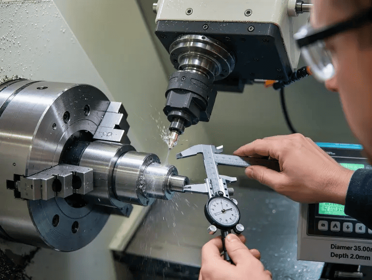
The finishing stage brings the shaft to its final dimensional and surface quality targets. At this point, material removal is minimal, typically 0.15 mm to 0.25 mm per side, and the emphasis shifts entirely to accuracy and surface condition.
- Achieving final diameter tolerances: Finishing passes are programmed with low feed rates (typically 0.05 to 0.15 mm/rev) and high cutting speeds to achieve smooth, accurate surfaces. In-process measurement between passes allows the operator to verify the diameter and adjust tool offsets if the dimension is trending out of tolerance due to tool wear.
- Surface finish optimization: The theoretical surface roughness on a turned surface is directly related to feed rate and nose radius. Reducing the feed rate or increasing the nose radius both improve surface finish, and the relationship is well established in cutting theory. For bearing seats and seal surfaces, Ra values must be verified against drawing requirements before the part is accepted.
- Final tool passes for precision surfaces: On critical diameter zones such as bearing seats, it is common practice to take a spring pass, a repeat of the final finishing path with no additional infeed, to remove any residual elastic deflection in the tool-workpiece system and achieve the most accurate diameter possible.
Tooling Strategies for Shaft Step Turning
Tool selection in step turning is not simply a matter of picking an insert and starting the cut. Every tooling decision, from insert geometry to nose radius to tool holder orientation, has a direct consequence on dimensional accuracy, surface finish, tool life, and cycle time. In shaft step turning specifically, the tooling must be capable of producing both cylindrical surfaces and shoulder faces, often within a single toolpath, which places unique demands on insert geometry and tool rigidity.
Roughing Tools for Heavy Material Removal
Roughing tools are selected primarily for their ability to remove large volumes of material efficiently while withstanding the high cutting forces involved. Key characteristics include:
- Insert shape: Trigon (W-shape) and square inserts are commonly used for roughing due to their large included angle, which provides high edge strength and resistance to chipping under interrupted or heavy cuts.
- Lead angle: A positive lead angle (entering angle greater than 90 degrees) directs cutting forces toward the spindle and chuck rather than radially into the workpiece, reducing deflection during roughing of long shafts.
- Insert grade: For steel shafts, coated carbide grades with TiCN or Al2O3 coatings are standard in roughing applications. These coatings provide thermal resistance and reduce crater wear at the high cutting temperatures generated during aggressive material removal.
- Chip breaker geometry: Roughing inserts should incorporate a robust chip breaker to control chip form and prevent long, continuous chips from wrapping around the workpiece or damaging the machined surface.
For example, when roughing a medium carbon steel shaft (such as AISI 1045) from 80 mm bar stock down to a 45 mm bearing seat, a trigon insert with a TiCN-coated carbide grade running at 200 to 250 m/min cutting speed and 0.3 mm/rev feed is a representative starting condition. [5]
Finishing Inserts for Dimensional Accuracy
Finishing inserts operate under fundamentally different conditions from roughing tools. The priority shifts from material removal rate to surface integrity and dimensional control.
Step Turning for Engineers & Operators
- Insert shape: Diamond-shaped (55° or 35° included angle) and trigon inserts are preferred for finishing. Their sharp point geometry allows clean shoulder definition and good surface finish at low feed rates.
- Nose radius selection: Nose radius has a direct influence on both surface roughness and cutting force. A larger nose radius (0.8 mm or 1.2 mm) produces a better theoretical surface finish at a given feed rate but generates higher radial cutting forces, which can cause deflection in slender shafts. A smaller nose radius (0.4 mm) reduces radial force but requires a lower feed rate to achieve the same surface quality. Selecting the appropriate nose radius requires balancing these competing factors against shaft geometry.
- Insert grade: Finishing grades are typically fine-grained uncoated carbide or PVD-coated grades with sharp cutting edges. These grades prioritize edge sharpness and dimensional consistency over wear resistance, as finishing cuts generate lower thermal loads than roughing.
- Wiper inserts: For applications requiring both good surface finish and acceptable feed rates, wiper inserts incorporate a secondary flat on the cutting edge that burnishes the machined surface. These are particularly useful on bearing seat and seal surface zones where Ra requirements are stringent. [6]
Shoulder and Facing Tool Considerations
Producing a clean, square shoulder in a step turning operation requires specific attention to tool geometry and approach angle.
- 93-degree entering angle tools: These are the most common choice for step turning because the 93-degree lead angle allows the tool to cut both the cylindrical surface and the shoulder face in a single pass without repositioning. The slight positive lead angle also helps direct chip flow away from the machined surface.
- Neutral or negative rake geometry: For shoulder facing, a neutral rake insert reduces the tendency for the tool to dig into the shoulder face, producing a flatter and more accurate surface.
- Undercutting at shoulder roots: In some designs, a small undercut groove is machined at the shoulder root before finishing. This ensures that the mating component seats fully against the shoulder face without being obstructed by any slight rounding of the corner that may result from the insert nose radius. This is standard practice in bearing seat machining.
Insert Geometry, Nose Radius, and Tool Strength
The relationship between insert geometry and machining outcome in step turning can be summarized around three key parameters:
- The included angle governs insert strength. An 80-degree diamond insert is stronger than a 35-degree diamond insert, making it more suitable for interrupted cuts and heavy passes. However, the sharper geometry of a 35-degree insert is necessary when machining into tight shoulder corners or narrow steps.
- Clearance angle affects the tendency of the insert to rub against the machined surface. Positive clearance angles reduce rubbing and improve surface finish, but weaken the cutting edge. Negative clearance angles increase edge strength but require higher cutting forces.
- Nose radius controls the transition between the cylindrical face and the shoulder face. A nose radius that is too large will leave material in the shoulder corner, requiring an additional facing pass. The nose radius must always be smaller than the fillet radius specified at the shoulder root on the part drawing, or the programmed fillet will be undersized.
Matching insert geometry to the specific requirements of each shaft zone, rather than using a single insert for the entire operation, is a hallmark of a well-planned step turning process.
Conclusion
CNC step turning stands as the defining process for producing multi-diameter shafts that meet the geometric and functional demands of modern rotating machinery. From the initial understanding of stepped shaft geometry through workpiece setup, roughing, shoulder formation, finishing, and tooling strategy, each stage of the process is governed by a clear engineering logic. The precision of each diameter zone, the squareness of each shoulder face, and the surface condition of each functional section are not independent concerns; they are interconnected outcomes of a well-planned and consistently executed machining process.
As shaft designs continue to grow in complexity and tolerance requirements tighten across industries, the fundamentals covered here remain the foundation on which advanced process planning is built. Proper geometry understanding, disciplined workflow sequencing, and informed tooling selection are what separate a shaft that merely resembles the drawing from one that performs reliably in service. Mastering these fundamentals is not a starting point to move beyond; it is a standard to maintain at every level of shaft manufacturing practice.
References
Banerjee, S., Pawar, S. S., Bera, T. C., & Sangwan, K. S. (2022). An investigation on reduction of cutting energy consumption using High Efficiency Machining strategy. Procedia CIRP, 105, 198–203. https://doi.org/10.1016/j.procir.2022.02.033
Horava, C., Reznicek, M., & Ovsik, M. (2024). Influence of the number of inserts used for face milling on cutting forces and surface roughness. Materials, 17(24), 6052. https://doi.org/10.3390/ma17246052
Li, C., Zou, Z., Duan, W., Liu, J., Gu, F., & Ball, A. D. (2023). Characterizing the Vibration Responses of Flexible Workpieces during the Turning Process for Quality Control. Applied Sciences, 13(23), 12611. https://doi.org/10.3390/app132312611
Shigley, J., & Mischke, C. (2001). SHAFTS AND BEARINGS. In Part 5 of 6. https://www.uobabylon.edu.iq/eprints/publication_10_8164_6209.pdf
Son, N. P. (2024). A comprehensive review on cutting tool material in hard turning performance. Engineering and Technology Journal, 09(04). https://doi.org/10.47191/etj/v9i04.16
Zahid, M. N. O., Case, K., & Watts, D. (2014). Optimization of roughing operations in CNC machining for rapid manufacturing processes. Production & Manufacturing Research, 2(1), 519–529. https://doi.org/10.1080/21693277.2014.938277