

Flatness, perpendicularity, and parallelism are fundamental geometric controls in CNC-machined parts, yet they are often treated as secondary to size tolerances. In practice, these requirements define how surfaces relate to one another and how a part behaves once it is assembled. A component can meet every dimensional limit on a drawing and still fail to function if its surfaces are not properly oriented. These geometric relationships directly affect load distribution, alignment, sealing, and motion accuracy.
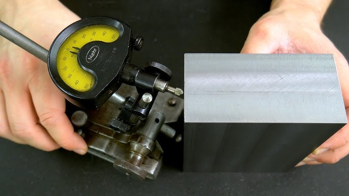
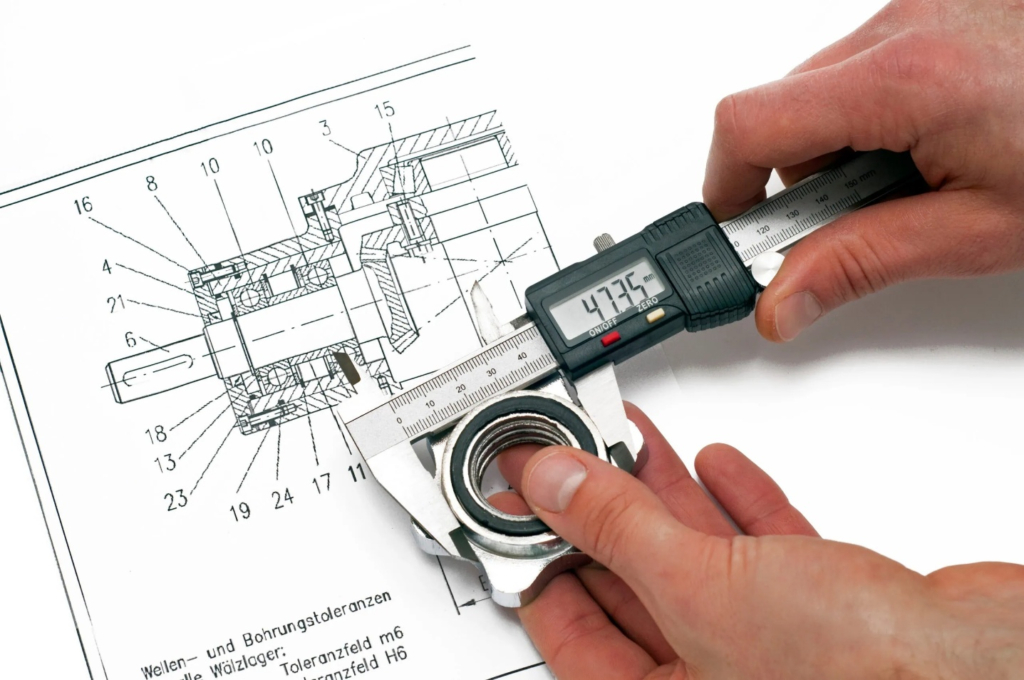
Measuring flatness, parallelism, and perpendicularity on a surface plate
When these tolerances are misunderstood or poorly specified, the consequences appear later in the process. Assembly difficulties, inconsistent inspection results, and unexplained performance issues become common. In many cases, the root cause is not a machining error but unclear design intent. This article explains what flatness, perpendicularity, and parallelism actually control, how they are measured in real manufacturing environments, and why their impact is frequently underestimated during design.
What Flatness, Perpendicularity, and Parallelism Really Control
Flatness, perpendicularity, and parallelism are often grouped together, but each controls a different aspect of part geometry. The most common misunderstanding is assuming they are automatically satisfied when size tolerances are tight. In reality, these controls exist precisely because size alone cannot define how surfaces and features relate to one another.
Flatness
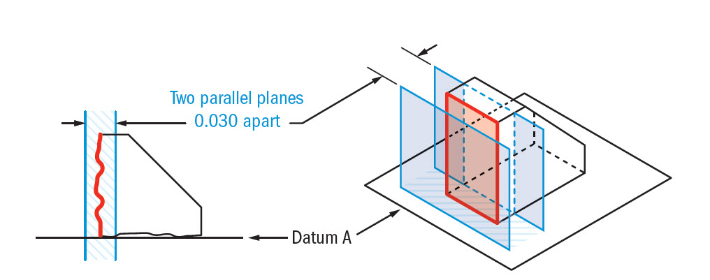
Flatness controls how much a surface deviates from a perfectly flat plane. It applies to a single surface only and does not reference any datum. The tolerance zone is defined by two parallel planes, and the entire surface must lie between them.
This means a surface can be within thickness tolerance and still fail flatness. A face that is slightly bowed or twisted may measure correctly at several points but still create functional problems. Flatness is critical for sealing surfaces, mounting faces, and areas where load must be evenly distributed. Poor flatness leads to point contact, localized stress, and inconsistent clamping forces, even when all dimensions appear acceptable.
Perpendicularity
Perpendicularity controls how close a surface, axis, or feature is to a true 90-degree relationship with a referenced datum. Unlike flatness, perpendicularity always relies on a datum to define orientation. It applies not only to faces but also to holes, pins, and shafts.
This tolerance is essential for alignment and motion accuracy. A hole that is slightly angled relative to its datum surface may still be in size, but it can introduce side loading into fasteners, bearings, or mating components. Over time, these small angular errors cause uneven wear, binding, or assembly difficulty. Perpendicularity ensures that features engage as intended, not just that they fit on paper.
Parallelism
Parallelism controls how evenly a surface or axis remains aligned relative to a datum feature. It does not control location or distance between features, only their orientation. This distinction is frequently overlooked.
Parallelism is especially important for sliding components, stacked assemblies, and parts that rely on uniform spacing. Non-parallel faces can cause binding in guideways, uneven wear in moving parts, and inconsistent gaps in assemblies. Even when parts assemble without force, poor parallelism often shows up later as noise, friction, or premature failure.
A Critical Distinction
Size tolerances define how big or small a feature can be. They do not control surface orientation or geometric relationships. A part can be fully within size limits and still fail its functional role due to poor flatness, perpendicularity, or parallelism. These geometric tolerances exist to control behavior, not just dimensions, and understanding this distinction is essential for both design and manufacturing.
Why These Tolerances Directly Affect Part Quality
Flatness, perpendicularity, and parallelism are not abstract drawing requirements. They directly influence how a part behaves under load, how easily it assembles, and how long it performs as intended. When these controls are loose or missing, problems often appear outside the machining department, which makes the root cause harder to identify.
Assembly Fit and Stress
Poor flatness is one of the most common sources of assembly issues. A mounting face that is not flat will rock during assembly, even if bolt patterns and hole sizes are correct. As fasteners are tightened, contact shifts to high spots, creating uneven clamping loads. This leads to distorted components, cracked housings, and fasteners that loosen over time.
Perpendicularity errors introduce unintended side loads. A shaft that is not square to its mounting surface forces bearings to operate under misalignment. Pins and fasteners are pushed into bending rather than pure shear. These stresses may not cause immediate failure, but they reduce fatigue life and increase wear.
Parallelism errors affect how parts interact across larger surfaces. Non-parallel faces create wedge effects that cause binding in sliding assemblies and uneven pressure in stacked components. Even small angular deviations can generate significant force when parts are constrained during assembly.
Functional Accuracy
Many functional issues trace back to orientation errors rather than size. Misaligned holes affect dowel pin engagement and press fits, leading to assembly force variation and inconsistent positional accuracy. Features intended to guide motion, such as rails or slots, lose precision when their surfaces are not parallel.
Calling Out Flatness and Parallelism
Angular errors also compound across assemblies. A small perpendicularity error in one component may seem insignificant, but when multiple parts are stacked, the resulting misalignment becomes large enough to affect performance. Motion paths shift, clearances change, and components begin to interfere in ways that are difficult to predict from individual drawings.
Cosmetic and Perceived Quality
Geometric errors are often visible, even when dimensions are technically correct. Gaps between mating surfaces, uneven contact lines, and misaligned features reduce perceived build quality. In consumer products, these issues are immediately noticeable. In automotive and aerospace components, they raise concerns about reliability and workmanship.
Customers and inspectors may not identify flatness or parallelism by name, but they recognize when parts do not sit square, align cleanly, or assemble smoothly. In this way, geometric tolerances influence not only functional quality but also confidence in the product as a whole.
How Inspectors Measure Flatness, Perpendicularity, and Parallelism
Inspection is where geometric tolerances become tangible. What looks straightforward on a drawing often becomes more complex once a real part, real fixtures, and real environmental conditions are involved. Understanding how these tolerances are measured helps explain why results can vary and why overly tight requirements quickly increase cost.
Common Measurement Methods
Inspectors use different tools depending on tolerance level, part size, and production volume. The most common methods include:
- Surface plate with dial indicator
- Used to check flatness by sweeping the surface and recording the total indicator variation
- Simple, repeatable, and effective for shop-floor verification
- Accuracy depends heavily on setup and operator technique
- Height gauge sweeps
- Often used to assess parallelism or perpendicularity relative to a datum surface
- Suitable for larger parts where direct indicator access is limited
- Sensitive to surface finish and probe contact consistency
- Granite fixtures with reference datums
- Provide stable datum references for orientation checks
- Common in inspection rooms and controlled environments
- Require careful part seating to avoid false readings
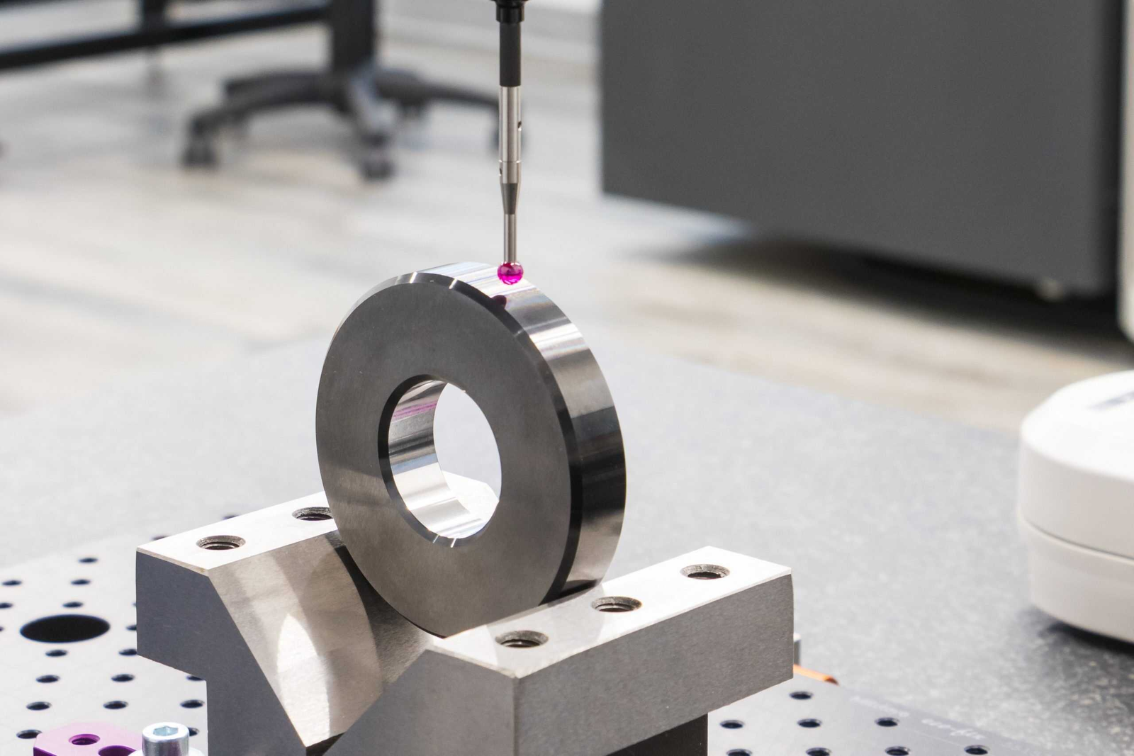
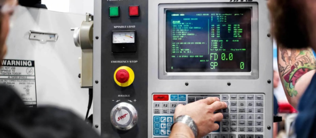
- Coordinate Measuring Machines (CMMs)
- Capable of evaluating complex geometry with high precision
- Measure orientation by calculating best-fit planes and axes
- Results depend on sampling strategy, alignment, and software interpretation
Practical Inspection Challenges
Even with the right equipment, measuring geometry is rarely as simple as placing a probe on a surface. Common challenges include:
- Datum selection
- Different datum choices can produce different results for the same part
- Poor datum definition on drawings leads to inconsistent inspection outcomes
- Fixturing effects
- Clamping or supporting a part can distort thin or stressed components
- A part may measure within tolerance when fixtured, but fail in the free state
- Temperature influence
- Small temperature changes can affect large or high-precision parts
- Differences between shop and inspection room conditions matter
- Probing force and contact
- Excessive probing force can deflect thin surfaces
- Light contact improves accuracy but increases measurement time
Shop-Floor Checks vs CMM Reality
There is often a gap between shop-floor checks and formal inspection results. This difference is not necessarily due to error but to resolution and intent.
- Shop-floor methods are effective at catching gross flatness and alignment issues quickly
- CMMs reveal subtle orientation errors that manual methods may not detect
- Tight geometric tolerances increase:
- Measurement time
- Programming complexity
- Disputes between manufacturing and quality teams
When tolerances are tighter than function requires, inspection becomes a bottleneck rather than a safeguard. Understanding how measurements are performed helps designers specify limits that can be verified reliably and consistently.
Why Designers Often Underestimate These Requirements
Geometric tolerances are frequently underestimated during design, not because of negligence, but because their effects are not immediately visible in CAD models. Flatness, perpendicularity, and parallelism problems usually appear after parts leave the drawing stage, which disconnects the cause from the effect.
Overreliance on Size Tolerances
A common assumption is that controlling size automatically controls geometry. Designers often believe that tight thickness or diameter tolerances will naturally produce flat or square features. In reality, machining processes can easily hold size while allowing orientation errors to remain.
- A face can meet thickness limits and still be bowed.
- A hole can be in diameter but angled relative to its mounting surface.
- Two faces can be correctly spaced yet not parallel.
Unless geometric tolerances are explicitly specified, these conditions are considered acceptable, even if they compromise function.
Limited Feedback from Manufacturing
CAD models represent ideal geometry. They do not show tool deflection, residual stress, or part movement during machining. Without regular feedback from machinists and inspectors, designers may underestimate how parts behave once material is removed.
- Long tools deflect under cutting load.
- Thin walls move after unclamping.
- Residual stress causes parts to warp after machining.
These effects are normal in manufacturing, but they are rarely visible to designers who do not see the parts on the shop floor.
Cost and Capability Gaps
Geometric tolerances directly influence cost. Tighter flatness, perpendicularity, and parallelism limits require more controlled machining processes and more time-consuming inspection.
- Additional setups may be required to control orientation.
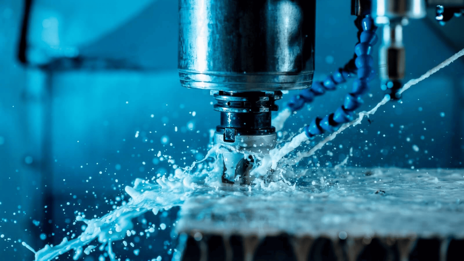
- Slower cutting strategies are often needed to reduce distortion.
- Inspection effort increases as tolerance limits tighten.
When these realities are not discussed early, designs move forward with unrealistic requirements. The most common outcome is that parts meet drawing requirements in isolation but fail during assembly. At that stage, changes are expensive, schedules are impacted, and responsibility becomes difficult to assign.
Designing and Specifying These Tolerances More Effectively
Flatness, perpendicularity, and parallelism should be applied deliberately, not as default additions to a drawing. Effective specification starts with understanding how the part functions in its final assembly and which geometric relationships actually matter. When tolerances reflect real functional needs, quality improves without unnecessary cost.
Use Geometry Where the Function Depends on It
Geometric tolerances should be placed where surface relationships directly affect performance. Sealing surfaces rely on flatness to maintain uniform contact pressure and prevent leakage. Mating faces depend on parallelism to ensure even load transfer and predictable assembly behavior. Alignment features such as dowel holes, bearing seats, and guide surfaces require perpendicularity to maintain accuracy and reduce wear.
Applying these controls selectively clarifies design intent. It tells manufacturing and inspection teams which relationships are critical and which variations are acceptable.
Keep Tolerances Functional, Not Ideal
Designs often inherit tolerances from older drawings without reassessment. While this may appear safe, it frequently results in over-specified geometry that adds cost without improving performance. Tolerances should be defined by what the part needs to do, not by what looks precise on a drawing.

Functional limits allow manufacturing flexibility while still protecting performance. When tolerances are tighter than necessary, machining becomes slower, inspection becomes more complex, and rejection rates increase. Clear, realistic limits reduce variation where it matters and avoid control where it does not.
Collaborate Early Across Disciplines
The most effective tolerance decisions are made before a drawing is released. Early collaboration between designers, machinists, and inspectors helps identify potential problems while changes are still inexpensive.
Manufacturing input clarifies what processes can realistically achieve. Inspection feedback ensures tolerances can be verified without excessive effort. Reviewing tolerance stack-ups and inspection methods during design prevents late-stage surprises and reduces the risk of parts that meet drawings but fail in service.
Common Failure Scenarios Caused by Poor Geometric Control
Many problems attributed to machining quality, assembly error, or component wear are actually caused by missing or inadequate geometric tolerances. These failures often appear intermittently, which makes them difficult to trace back to flatness, perpendicularity, or parallelism issues.
Geometric Dimensioning & Tolerancing
Rocking and Loss of Clamp Load
One of the most frequent failure modes comes from insufficient flatness on mounting surfaces. Parts appear secure during assembly, but over time, fasteners loosen, or components shift. The root cause is uneven surface contact. As bolts are tightened, the load concentrates on a few high points rather than being distributed across the surface. Thermal cycling and vibration then accelerate loosening.
This issue is especially common in housings, brackets, and interface plates where flatness is assumed rather than specified.
Premature Wear in Bearings and Guides
Perpendicularity errors often show up as shortened component life. Bearings that should run concentrically are forced to operate under misalignment. Guides and rails experience uneven contact, which increases friction and wear on one side.
In many cases, these components pass incoming inspection because the sizes are correct. The failure only becomes apparent after hours or cycles of operation, at which point the geometric cause is no longer obvious.
Binding and Inconsistent Motion
Parallelism errors frequently cause motion problems. Sliding components may feel smooth at one position but bind at another. Actuators require more force than expected, and motion becomes noisy or erratic.
These problems are difficult to correct after assembly. Adjustments and shims may mask the issue temporarily, but they do not address the underlying orientation error. Proper parallelism control at the part level prevents these issues from occurring in the first place.
Assembly That Works Only One Way
Another warning sign is an assembly that functions correctly only in a specific orientation or sequence. Components may need to be forced into position or aligned manually by experienced technicians. While the product may still ship, this variability increases labor costs and reduces consistency.
In many cases, the cause is a combination of flatness, perpendicularity, and parallelism issues that were never explicitly controlled on the drawing.
Conclusion
Flatness, perpendicularity, and parallelism define how machined parts truly interact, not just how they measure. These controls govern contact, alignment, and motion, which directly influence performance, reliability, and service life. When geometry is treated as secondary to size, parts may meet drawing requirements yet fail to perform their intended function.
Many quality issues linked to assembly difficulty, premature wear, or inconsistent operation can be traced back to misunderstood or missing geometric tolerances. These problems are often expensive to diagnose because they appear after machining is complete and components are already in use. Clear specification of flatness, perpendicularity, and parallelism helps prevent these issues by making functional intent explicit.
Effective use of geometric tolerances requires more than technical knowledge. It depends on early collaboration between design, manufacturing, and inspection teams. When tolerances are realistic, functional, and measurable, they improve consistency while controlling cost. In this way, flatness, perpendicularity, and parallelism become practical tools for quality, not just symbols on a drawing.

