What are Technical Drawings?
Technical drawings are files that include all of the 2D drawings that are specifically specified for the component that you intend to build. By showing details (such as internal and exterior threads, various surface finishes, annotations, measurements, and tolerances) that can be difficult to portray using 3D CAD models, they provide a clear perspective of the parts.
These drawings help limit the possibility of manufacturing mistakes by making it simpler for cnc milling service factories to comprehend your production project and provide precise cost estimates.
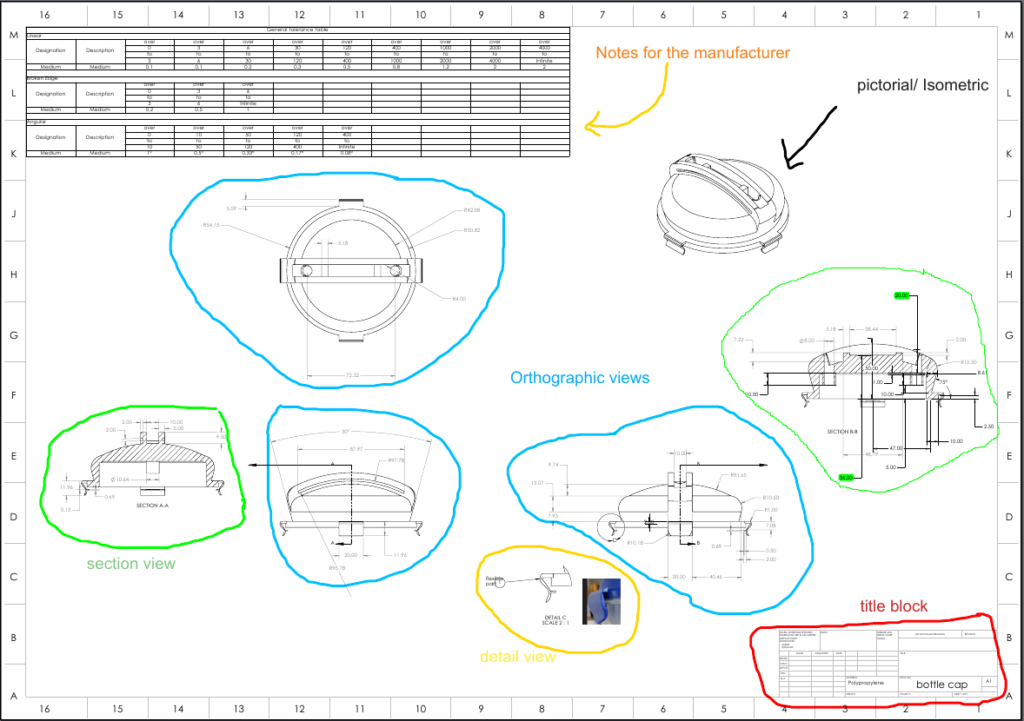
Components of CNC machining Technical Drawings
The following essential elements are frequently present in CNC Machining Drawings:
- Coordinate information
- a title blocks.
- a pictorial or isometric view of the component.
- the part's primary orthographic viewpoints.
- views in sections or in detail.
- Notes for the manufacturer
Coordinate information
This information map enables the use of the location of CNC machined components as a reference point. Large and intricate technical drawings typically employ it.
Title block
It is positioned at the document's bottom right corner. It includes the fundamental details of the parts that need to be manufactured, such the part name, part number, cnc milling parts supplier, specifications for the materials and finishing, drawing number, and much more. It also includes the part's technical details, such as system measurements, projection angle, surface finish specifications, scale, and material
Pictorial or isometric view of the component.
Often referred to as a pictorial view, it offers 3D representations of the component that will be made. This makes it easier for the reader to rapidly comprehend the section. Isometric perspectives mix the undistorted display with the appearance of depth.
Orthographic viewpoints
These are two-dimensional representations of the three-dimensional item, showing each side of the bounding box in turn and accurately depicting the part's form. In order to make it easier to communicate the parts' size and characteristics, just the edges of the pieces are drawn in this style.
Two or three orthographic views are often enough to correctly depict the whole geometry for most sections.
Sectional views
It is a two-dimensional depiction of the cut-through section. This view reveals the intrinsic characteristics of the components that are hidden from view in the orthographic and isometric views. These images are distinguished by a cross-section taken along a particular cut plane.
Multiple section views may be included in technical drawings, and each section view and each cutting line are connected by two letters (for example A-A, B-B and so on). The direction is indicated by the arrows on the cutting line.
Detail views
It displays the intricate features of the orthographic view.
Notes for the manufacturer
Although it is not necessary to add remarks to the manufacturer's technical drawing in order to obtain a quote, doing so is quite crucial. They provide extra details that were left out of the original plans.
Symbols, as opposed to text, are frequently used in manufacturer notes. Surface roughness, for instance, is frequently marked with a symbol.
Developing CNC Machining Drawings
The following are some crucial actions to take while creating technical drawings for CNC machining.
- Step 1
Identify the most crucial perspectives and center the appropriate orthographic there, allowing adequate space between them to add dimensions.
- Step 2
Consider adding section views or detail views if your part has internal features or intricate, challenging-to-dimension sections.
- Step 3
All views should include construction lines. Included in construction lines are centerlines (used to specify axes of symmetry or planes), centermarks, and centermark patterns (to define the location of the center of holes or of circular patterns).
- Step 4
When adding dimensions to your CNC design, start with the ones that matter the most (we give more tips on this in the next section).
- Step 5
Detail the placement, dimensions, and length of each thread.
- Step 6
Tolerances should be added to features that require greater precision than the default tolerance. For metals, we adhere to ISO 2768; for plastics, we use -medium or -fine.
- Step 7
Complete the title block, making care to include all pertinent information and specifications that go beyond accepted standards (such as surface finish and deburring) in the supplementary remarks. Export your drawing as a PDF file after it's finished, then use the quotation builder to link it to your order.
Importance of CNC machining Technical Drawings
One of the crucial first steps in the creation of 3D models for CNC machining is the use of technical drawings. The following is the function of technical drawings:
- The 3D CAD design is helpful for pre-programming the machine with the necessary commands, but a technical drawing is helpful for details. For instance, the majority of components, including screws and nuts, contain threads, which must be carefully examined to ensure they are correct on a physical level. The same holds true for the part's multiple surfaces' surface treatment. These traits are adequately illustrated in technical drawings.
- Technical illustration showing both a detailed section-by-section view and an isometric perspective. As a result, it is simple to comprehend important information like tolerances, annotations, measurements, and much more. The machinist can comprehend the intricate features of the pieces to be made using the information stated above.
- A critical component of CNC machining is hole drilling in the appropriate slot, particularly for PCBs and other items. Technical drawings make depth, sinks, and other aspects easier to grasp.
Ways of Understanding Complex Machining Drawings
The standard structure's dimensioning approach
The following are common hole dimensioning techniques:
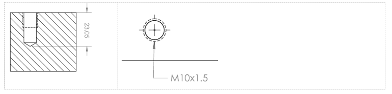
Blind Hole
Countersink Hole
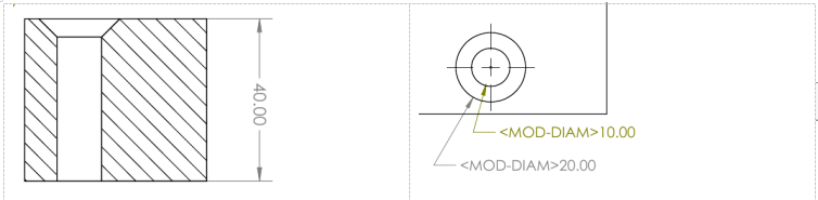
Counterbore

Structure on Parts Machined
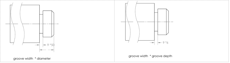
Wheel overtravel grooves and undercuts
When cutting components, the undercut groove or the grinding wheel overtravel groove should be pre-machined at the step of the treated surface to make tool withdrawal easier and guarantee that the contact surfaces of the essential parts are near during assembly.
According to "groove width diameter" or "groove width groove depth," the amount of the undercut while turning the outer circle may often be indicated. When grinding an outer circle or an outer circle and an end face, there is a groove caused by the overtravel of the grinding wheel.
Drilling Structure
A drill bit used to create a blind hole has a bottom cone angle of 120°. The cylindrical component of the hole, excluding the cone pit, is what is meant by the drilling depth. A circular table with a cone angle of 120 degrees, its design, and its size notation are also present at the stepwise drilling transition.
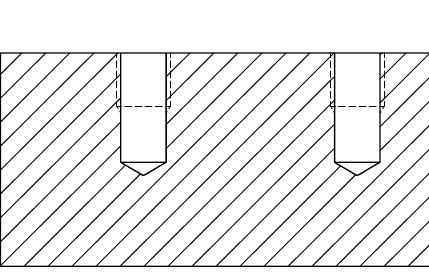
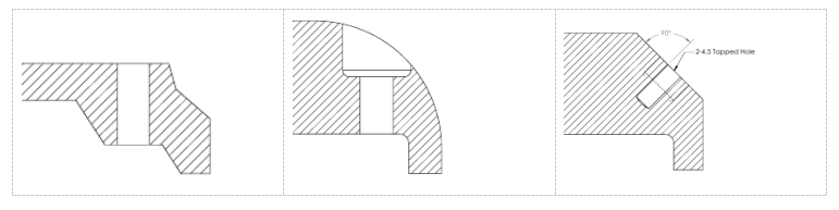
To achieve drilling precision and prevent the drill from breaking, it is necessary that the drill's axis be as perpendicular to the drilled hole's end face as is physically possible. The three drilling end faces' precise structural arrangement is shown below.
Bosses And Pits
In general, processing is done on a part's contact surface with other components. Bosses and pits are frequently incorporated into the design of the castings in order to minimize the processing area and provide proper contact between the surfaces of the pieces. Bolted support surface boss or recessed support surface shape. A groove structure is created to minimize the processing area.
Common Part Structure
Shaft Parts
Shafts, bushings, and other elements are typically included in such components. Drawing a basic view and adding the relevant cross-sectional views and measurements will allow you to convey the views' primary form aspects and local structure. It is recommended to find a position where the axis is the lateral vertical line. The axis is often set horizontally for projection to make it easier to examine images as they are being processed.
Its axis is frequently utilized as the reference point for radial size markings on bushing components. In this approach, the design specifications and the processing process reference (the center hole of the shaft is retained by the thimble at both ends while the shaft pieces are treated on the lathe) are combined. Important end faces, contact faces (shoulders), or machined faces are frequently selected using the length direction datum.
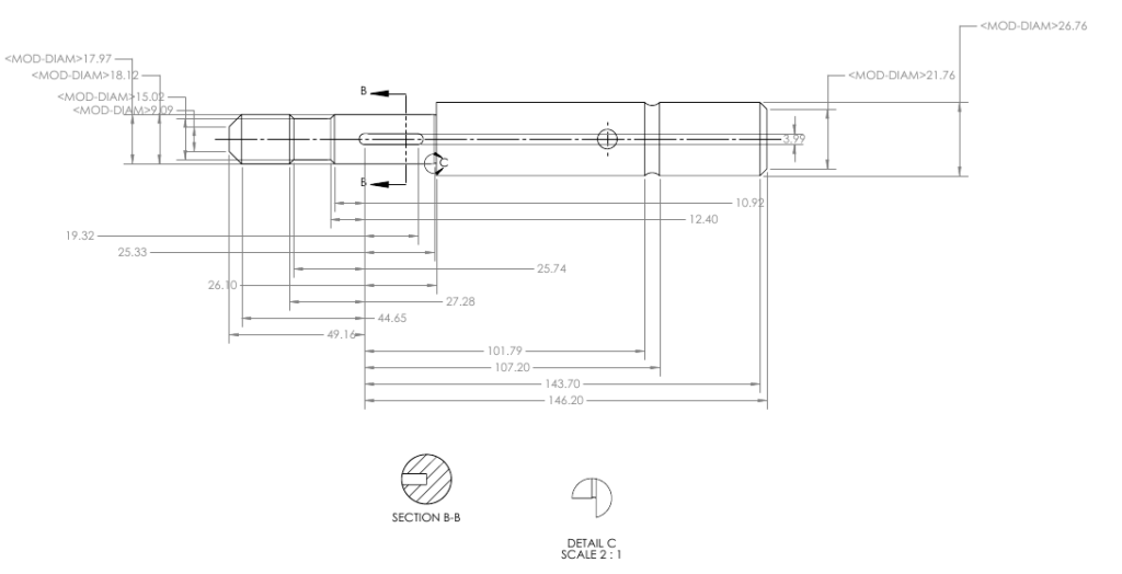
As indicated in the diagram, the right shoulder is chosen as the primary dimension reference in the length direction, and measurements like 12.40, 17.97, 19.32, and 101.79 are inserted. This shoulder has a surface roughness of Ra6.3.
The entire shaft length will then be marked at 195.36 by using the right shaft end as an auxiliary base in the length direction.
Disc Cover Components
These parts often include end caps, valve caps, gears, and other elements, and their fundamental form is a flat disc. Their primary construction is essentially a revolving body, typically with different flange forms and evenly spaced circular holes. as well as ribs and other regional features. To convey the shape and uniform structure of the part, other views (such as left view, right view, or top view) should be added after choosing the front view, which is often the cross-sectional view of the symmetry plane or the axis of rotation.
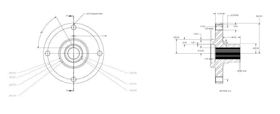
When designating the size of disc cover components, the shaft hole axis is typically used as the radial dimension reference, and the significant end face is frequently the primary dimension reference in the length direction.
Components of a fork frame
Forks, connecting rods, bearings, and other components are frequently found in such parts. The working posture and form features are the major factors to take into account while picking the main view due to their varying processing positions. Two or more fundamental views are frequently necessary for the choice of additional views, and the local structure of the component must be expressed using the relevant local views, cross-sectional views, etc. The footrest components drawing presents a polished and unambiguous viewpoint. The breadth of the bearing and ribs may be expressed without using the right view. The cross-section is better suitable for ribs with a T-shape.
The installation base surface or the part's symmetry plane are often used as the dimension reference for designating the dimensions of fork bracket components.
Surface Roughness
Surface roughness is the micro-geometric property of the small-spaced peaks and valleys on the part's surface. This is mostly caused by the tool marks the tool left on the part's surface and the plastic deformation of the metal's surface during cutting.
Another technical measure for assessing the surface quality of items is surface roughness. It affects the components' appearance, airtightness, wear resistance, functioning precision, and resistance to corrosion and wear.
Basic Deviations and Typical Tolerances
The national standard "Limits and Fits" mandates that the tolerance zone be formed of two components: standard tolerance and fundamental deviation, in order to simplify manufacturing, achieve part interchangeability, and satisfy various usage requirements. The tolerance zone's dimensions and placement are determined by the standard tolerance and the basic deviation, respectively.
Typical Tolerances
Basic size and tolerance class are what define the value of the standard tolerance. The tolerance level serves as a gauge for size accuracy. IT01, IT0, IT1,… IT18 are the 20 levels that make up the standard tolerance. From IT01 to IT18, its size accuracy falls. Standards that apply can be identified with the particular values of standard tolerances.
Basic Deviations
Basic deviation, which is used to describe the higher or lower deviation of the tolerance zone from the standard limit and fit's location of the zero line, often refers to the deviation that is near to the zero line. The fundamental deviation is the lower deviation when the tolerance zone is above the zero line and the higher deviation when it is below. There are a total of 28 fundamental variances, and the code is written in Latin characters with uppercase letters denoting holes and lowercase letters denoting shafts.
According to the concept of dimensional tolerance, the calculation formulae for the basic deviation and standard deviation are as follows: ES=EI+IT or EI=ES-IT
We welcome your valuable comments on our blog posts, and do not hesitate to contact us about machining related services.