What is Surface Roughness?
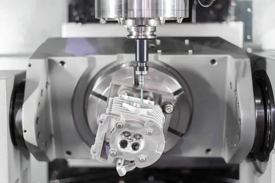
Surface roughness in CNC machining refers to the small imperfections on a machined surface created during the cutting process. It is a vital measure that can affect part performance, fit, and appearance. Measurements are given in micrometers, µm, and surface roughness is generally measured by either Ra (arithmetical average roughness) or Rz (average peak-to-valley height) measurement indexes to meet design requirements.
Key Surface Roughness Parameters
In CNC machining, accurate quantification of surface texture is important to part performance, life, and fit during assembly. Below are the most commonly used parameters to describe and control surface roughness:
Ra (Arithmetic Average Roughness)
Ra or arithmetic average roughness, is calculated as the average of the absolute value of the deviations of the surface profile from the mean line over a specific sampling length. Mathematically, Ra can be expressed in continuous form as:
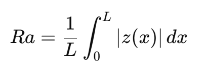
where z(x) is the deviation at location x and L is the sampling length. The value of Ra is that it provides a single numerical value for the overall smoothness of the surface, and it is often chosen as the specification for general quality control and aesthetic surfaces in many industries such as aerospace, automotive, and consumer electronics.
Rz (Average Maximum Height)
Rz, or the mean maximum height of the profile, includes the five highest peaks and the five deepest valleys in the sampling length and is calculated by averaging the peak-to-valley heights of these ten extreme values:
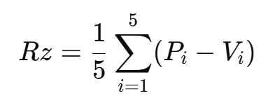
where Pi are the selected peak heights and Vi are the valley depths. Rz provides a more sensitive measure of localized surface defects, which provides a clear advantage for applications with tolerances where tight fits and seals are important (bearing interfaces, sealing surfaces, adhesion layers, etc.), as local deviations from the average may impair function.
Comparison: Ra vs. Rz
Ra provides a general understanding of surface roughness by averaging all deviations, which gives an overall picture of surface quality in an overall index (0.1-6.3 µm), while perhaps hiding important large peaks or valleys that could impose functional issues. Rz removes ends (10-50 µm) with a peak to valley height while still capturing a degree of surface disturbance which could affect dynamics or sealed interfaces. The downside of Ra is that it provides overall "average" smoothness without capturing sometimes problematic high peaks or deep valleys; Rz can emphasize selected defects, but may not be able to represent overall smoothness. In practice, Ra is most commonly used for all-in quality control and aesthetics, whereas Rz is most commonly used for functional surfaces where peak-to-valley differences could affect functional performance.
Other Common Indicators
Rt (Total Roughness)
Rt quantifies the total height of the roughness profile by locating the maximum peak and maximum valley over the evaluation length:
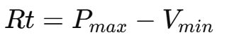
This parameter is a good measure for detecting extreme departures from flatness and is even useful for ensuring that no unacceptable peaks or grooves exist. It serves the overall quality control in this respect.
Rq (Root Mean Square Roughness)
Rq, or root mean square roughness, is the square root of the mean of the squares of the deviations from the mean line:
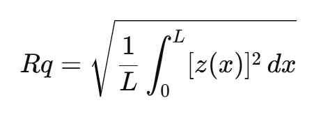
When you take the mean of the squares of the deviations (taking the square of deviations to do so) the resulting value gives more weight to larger peaks and valleys. Using this value is most appropriate in applying it to precision-bearing surfaces, optical surfaces, and in situations where not making small changes to the surface is critical to meeting objectives.
Lay
Lay defines the predominant direction of the pattern on the surface, which is usually dependent on the method used to create the surface (i.e., turning, milling, grinding). Lay does not measure roughness, but lays out the dominant direction of the peaks and valleys; the lay can affect the tribological behavior of a surface and adds to the plaited appearance of the surface.
Surface Roughness Standards & Notation
Following international surface roughness standards is the most important thing in CNC machining when you require accurate finishes and functional performance.
Surface texture requirements are defined in technical drawings using the international standard ISO 1302, which describes graphical symbols and notations that have clear meanings. You may find features like an "R" to identify radial lay, "⊥“ perpendicular lay or profile indicators, with these placed on part schematics to designate target Ra, Rz, or other parameters.
ISO 4287 defines the 2D profile parameters: Ra (the arithmetic average), Rz (the mean height of the five tallest peaks minus the mean depth of the five lowest valleys) and Rq (root mean square), all along one trace; ISO 25178 goes a step further to include full-field 3D characterization as well as an entire class of areal surface parameters and measurements defining complete surface topography. Using ISO 4287 and ISO 25178, manufacturers can choose the best metric for applications ranging from sealing interfaces on gaskets to ultra-precision optics.
ISO 16610 describes standardized filtering procedures—standard Gaussian, spline, or FFT filters, to separate the short-wavelength roughness from longer-wavelength waviness to ensure consistency in evaluation. When using these filters, engineers and QC labs can directly compare surface data from instruments and measurement methods.
Roughness Grade Systems
The DIN ISO 1302 system, which uses an "N" grade, provides 12 "N" grades (N1-N12), each with an allowable maximum Ra value. The use of "N" grades provides assurance of consistency of surface specifications in technical drawings and manufacturing. The relationship between N-grades and Ra is as follows:
| N Grade | N1 | N2 | N3 | N4 | N5 | N6 | N7 | N8 | N9 | N10 | N11 | N12 |
| Ra (µm) | 0.025 | 0.05 | 0.1 | 0.2 | 0.4 | 0.8 | 1.6 | 3.2 | 6.3 | 12.5 | 25 | 50 |
Statistical Relationship between Ra and Rz
While there is a relationship between the N-grades to Ra, there is no linear relationship between the N-grades to Rz, as each value has a totally different measurement principle. Ra provides average roughness, while Rz provides a measure of the peak to valley extremes.
For example:
A surface with Ra 3.2 µm (N8) would have an Rz value between 11.5 - 34.7 µm.
Increased roughness values significantly increase this range (for example Ra 50 µm ≈ ,Rz 156.2 - 272.6 µm).
Conversion Tools and Charts
While there is no statistical relationship of Ra to Rz, which would allow for an exact Ra↔Rz conversion, there are online conversion tools (such as Rz-Ra calculators) that provide conversion range data from empirical data. These tools:
- They are used to convert Rz to an Ra range and assign N-grades.
- Stress that values (like Rz ≈ 7×Ra ) are simply a rule-of-thumb and not suitable for engineering specifications.
For proper accuracy, measure with the parameter on the drawings, instead of converting to either Ra or Rz.
Measurement Techniques
Accurate characterization of surface texture in CNC machining is dependent upon a range of measurement techniques, in part based on size and/or specific materials. The key measurement techniques can vary widely, ranging from customarily used stylus (contact) profilometry to probe-based methods, as well as optical measurement techniques, each having their unique advantages to drive reliable data collections for quality control and functional performance.
Contact Profilometry (Stylus Methods)
Contact profilometers use a diamond or sapphire-tipped stylus that touches the surface and physically follows the surface profile. The vertical displacements of the stylus are converted into electrical signals to calculate a 2D roughness evaluation of the surface profile. Typical stylus tip radius is in the order of 2–10 µm, with vertical displacement resolution down to sub-nanometer levels, which is ideal for the measurement of Ra and Rz and conforming to relevant standards.
Non-Contact Methods
Non-contact techniques use light or laser triangulation, confocal microscopy, and optical interferometry to map surface topography and do not contact the part. Non-contact is helpful for potentially damaged soft finishes. A triangulation scan of height variation is made using two angled laser beams, whereas confocal and white-light interferometry take advantage of resistance to inertial measurements through spatial filtering and principles of interference, to achieve vertical resolution on the order of nanometers.
Atomic Force Microscopy (AFM)
AFM uses a nanoscale cantilever tip to "feel" the surface and generate quantitative data in three-dimensions, offering 5–10 nm for lateral and sub-nanometer resolution in vertical measurement. AFM is likely very valuable for nanometer-scale roughness, skewness, and kurtosis evaluation in academic work, as well as industrial work where spatial resolutions in the range of high-precision variations of fewer than 100 nm are necessary.
3D Scanning/Topography Mapping
Advanced, new-age 3D scanners and trochoidal areal profilometers employ an assortment of optical methods, such as focus variation, structured-light scanning, and digital holography, to map the entire complexion of the surface, allowing the user to determine surface textural parameters across a highly-complex geometry. The tools allow users to collect high-density 3D data in much shorter intervals and with the required detail for topography evaluations and process performance optimizations.
Achieving Target Surface Roughness in CNC Machining
Machining Parameters
- Cutting Speed and Feed Rate
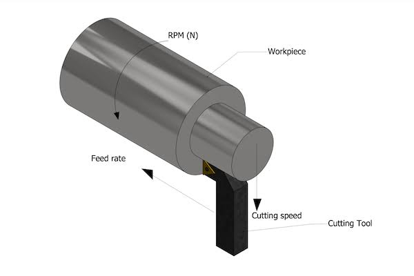
Higher cutting speeds reduce built‐up edge and tool marks, therefore producing smoother surfaces. However, abnormal and overly fast feeds produce shallower scallops, leading to increased surface roughness. Often, good surface finishes occur at speeds above 50 m/min with feeds of 0.1 mm/rev on machined surfaces and represent a balance between material removal rate and surface quality.
- Depth of Cut
Choosing a shallow depth of cut (usually about 1 mm or less) will reduce cutting forces and vibration that causes surface finishes to be uneven. The depth of cut specified by the tool manufacturer usually has less of an effect relative to feed rate, but a depth of cut of 0.5–1.5 mm is acceptable to maintain stability and achieve a consistent surface texture.
Tool Geometry and Condition
- Edge Radius, Rake Angle, and Relief Angle
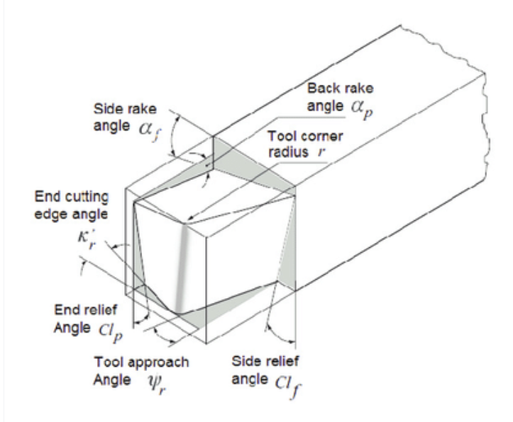
A smaller cutting edge radius will produce finer surfaces by limiting the area of residual tool marks left on the surface. Rake angles (+/- 5° to +15°) and relief angles (5°–15°) take advantage of optimum chip flow and cutting force to minimize imperfections in surface finish and minimize the risk of tool chatter.
- Coatings (TiN, DLC) and Wear
Common coatings such as TiN and DLC reduce friction, increase hardness, and delay flank wear, which allows sharpened cutting edges and surface finish quality for longer periods within the life of the tool. However, cutting forces throughout the lifetime of the tool may create micro‐chatter as wear progresses on the tool, resulting in surface finish degradation, and therefore, any tool that promotes chatter should be monitored for wear closely, and timely tool changes should be made.
Post Processing and Finishing
- Grinding, Lapping, Honing, Superfinishing
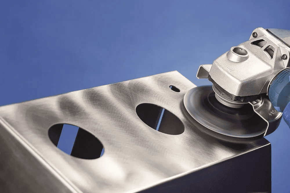
Abrasive processes may ultimately remove very little material to produce ultra-smooth surfaces. Grinding (Ra 0.1 - 1.0 µm) utilizes progressively finer grinding wheels, lapping uses slurry abrasives and abrasive for flatness, honing utilizes stones to produce a uniform surface, and superfinishing utilizes ultra-fine abrasives at low pressure to achieve Ra values ≤0.1 µm.
- Bead blasting, Electropolishing, Anodizing
Bead blasting utilizes glass beads launched with compressed air and will produce a consistent matte finish suitable for stress-relief applications. Electropolishing utilises an electrochemical process to smooth micro-peaks and add corrosion resistance. Anodizing represents a presumed controlled oxide layer that is able to substantially fill the valley of surface roughness to not only increase durability, but also improve surface aesthetics.
Selecting the Right Roughness for Your Application
Choosing the Right Roughness for Your Application is about matching surface finish with part function, desired visual impression, and limitations concerning manufacturing processes:
- Functional Characteristics: Wear, Sealing, Lubrication
For parts subjected to sliding or rolling contact, generally, the smoother the profile (i.e., Ra ≤ 0.8 µm) the better, to reduce friction and wear. And, sealing faces of an assembly must have the right valley depth (Ra 1.6–3.2 µm) to capture the lubricants and seal without leaking.
- Visual Finish vs. Non-Visible Components
Finished components expected by customers often take the assumption that they are completed to a fine or high-gloss finish (Ra ≤ 0.4 µm) because of the visual impression, whereas non-visible components can be unknown range of Ra 1.6 µm to Ra 3.2 µm, which allows for less cycle time and less cost to machine.
- Material Characteristics and Geometry Limitations
For instance, hard or abrasive materials may require special tooling or secondary super finishing in order to achieve the target roughness specified in the required time, while also minimizing excessive wear on the tooling. Further, close tolerance, tight radii, and deep pockets may limit any access by the cutter, which may then require additional work on part post fabrication (i.e., honing or electropolishing), to reach the Ra value specified.
Inspection & Quality Control
To properly measure surface roughness, you must first make an appropriate representative sampling, such as random or systematic, a priori, to make sure that you represent the entire lot's measurements. Then, you monitor the surface finish data with Statistical Process Control (SPC) tools like X-bar and R chart, which determine trends and diagnose when you are breaking an expected target roughness. You will measure process capability, using Cp and Cpk indices, based on a value of 1.3,3 which should mean the process is stable and capable of a predetermined Ra or Rz. This method attempts to minimize defects while maintaining a good level of quality in a CNC machining process.
Practical Examples
Knowing surface roughness parameters like Ra (Average Roughness) and Rz (Mean Peak-to-Valley Height) is essential in various industries, and here's how they help ensure function and reliability:
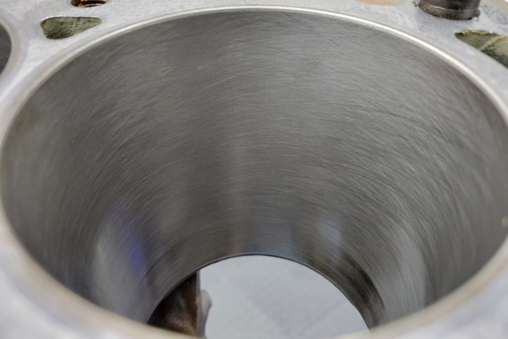
Automotive: Cylinder Walls
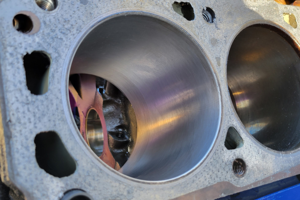
Engine cylinders must have ultra-smooth finishes (Ra 0.1–0.4 µm) to keep lubrication and limit friction. The Rz measurements allow the engineer to ensure that the peaks of the irregularities (valleys) are shallow enough to maintain the oil films so as not to cause metal-to-metal contact that would wear the surfaces together.
Aerospace: Fatigue-Critical Components
Usually, parts that are fatigue-critical, like wing fittings or turbine blades, have Ra values that are low or often < 0.8 µm to limit micro-cracking due to fatigue stresses. Rz measures peaks and valleys too — large peaks/valleys are the kissing cousin to fatigue failure, and lower Ra values should improve overall durability against vibrations, i.e., they have some relationship.
Medical: Implants
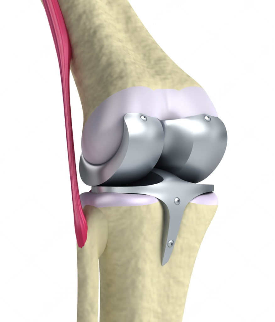
Ra of 0.4-1.6 µm is suitable for titanium hip or knee implants, and permits adequate biocompatibility and structural fixation of bone. The implant surface will possess some texture (controlled by the Rz), allowing for cell attachment, while the Ra should provide lower friction at the interfaces of the implant/joint. Increasing surface roughness may introduce inflammation to the surrounding tissue; at the opposite end of the spectrum, surfaces that are too smooth can limit osseointegration.
Optics: Lenses, Mirrors
Lenses require Ra <0.1µm (mirror finish), to avoid having light scatter uncontrollably. The Rz ensures there are no deep valleys significant enough to affect the end refraction. A lens that exhibits high Rz, when manufactured, will produce aberration and ultimately introduce failures in imaging systems, such as cameras and medical devices.
Summary
Surface roughness in CNC machining is typically quantified in terms of Ra (average roughness) and Rz (height from the highest peak to the lowest valley). A surface's roughness is also critical to the performance, aesthetics, and functionality of the part. The value of Ra gives an overall measure of the smoothness of the part surface. The value of Rz measures outliers or unwanted characteristics of the surface that may affect fit, sealing, or wear. For example, automotive cylinder wall surfaces are required to have a Ra of 0.1 – 0.4 µm in order to maintain oil films and prevent metal-to-metal contact. Aerospace components used in fatigue-critical applications (e.g. turbine blades) have a Ra requirement of <0.8 µm. Medical technology is another sector that leverages surface roughness, inclusive of titanium implants. The surface roughness of titanium implants is proposed to have a Ra value of 0.4 - 1.6 µm to balance cell adhesion to titanium while giving a low risk of inflammation. The optics industry is another industry requiring ultra-smooth surfaces with Ra values of <0.1 µm to minimize light scatter.
A finish can be influenced by cutting speed, feed rate, tool geometry, and depth of cut. The finish can also be influenced by post processes such as grinding, honing, and electropolishing. Surface roughness standards such as ISO 1302, 4287, and the DIN ISO 1302 are used to communicate how to provide roughness to a part in engineering drawings. Surface roughness is reported using the same methodology as "N" grades in a CONTINUUM fashion in engineering drawings to specify the overall quality of the surface. For measurement devices, there are contact and non-contact profilometers, optical scanners, and atomic force microscopy (AFM) devices that resolve to nanometers. For quality control, statistical process control (SPC) charts and indices Cp and Cpk can be used to monitor the actual surface roughness and ensure the surfaces achieve target values. These metrics support confidence that the product meets reliability and performance criteria across many industries and kinds of applications.