
Cradle-type versus swivel-head five-axis machines: How does machine structure affect part dimensions and machining accuracy?
Two five-axis CNC machining centers may advertise similar linear-axis travels but accommodate very different workpieces. A component that fits on one machine's table may become inaccessible when the table tilts, while another machine may struggle to reach the same features because its swiveling spindle head occupies valuable space.
When comparing trunnion and swivel-head five-axis CNC machines, the central question is how machine structure influences usable workpiece dimensions, cutting-tool accessibility, and dimensional accuracy.
Neither configuration is inherently more accurate. The right choice depends on where the rotary axes are located, how the workpiece is supported, the machine's geometric condition, and the tolerances required by the engineering drawing.
How Do Trunnion and Swivel-Head Five-Axis Machines Differ?
The fundamental difference between five-axis CNC machine configurations is where the rotary movements occur. Both architectures combine linear and rotary axes, but the distribution of those movements between the tool and workpiece changes the machine's mechanical behavior.
Trunnion/Cradle-Type: Rotary Motion on the Workpiece Side
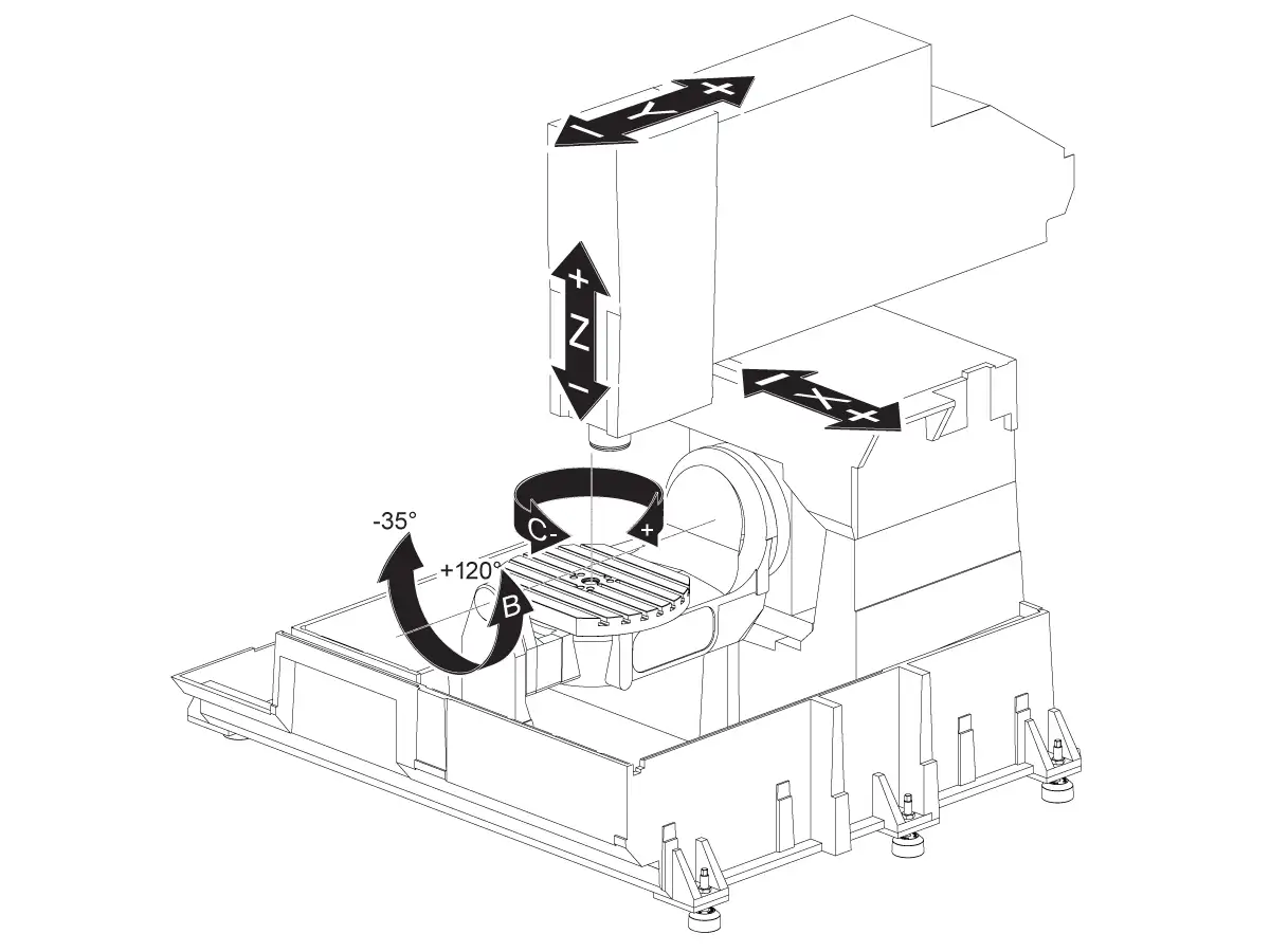
A trunnion-type five-axis CNC machine uses a tilting rotary table to orient the workpiece while the spindle maintains a fixed angular orientation relative to the machine structure.
The cradle supports the tilting assembly from both sides. The workpiece can rotate and tilt to expose different surfaces to the cutting tool.
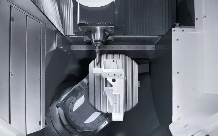
This arrangement is useful when the component and fixture fit within the available rotary envelope. Its limitations become more significant as workpiece dimensions, fixture height, or loading requirements increase.
Swivel-Head and Hybrid Configurations
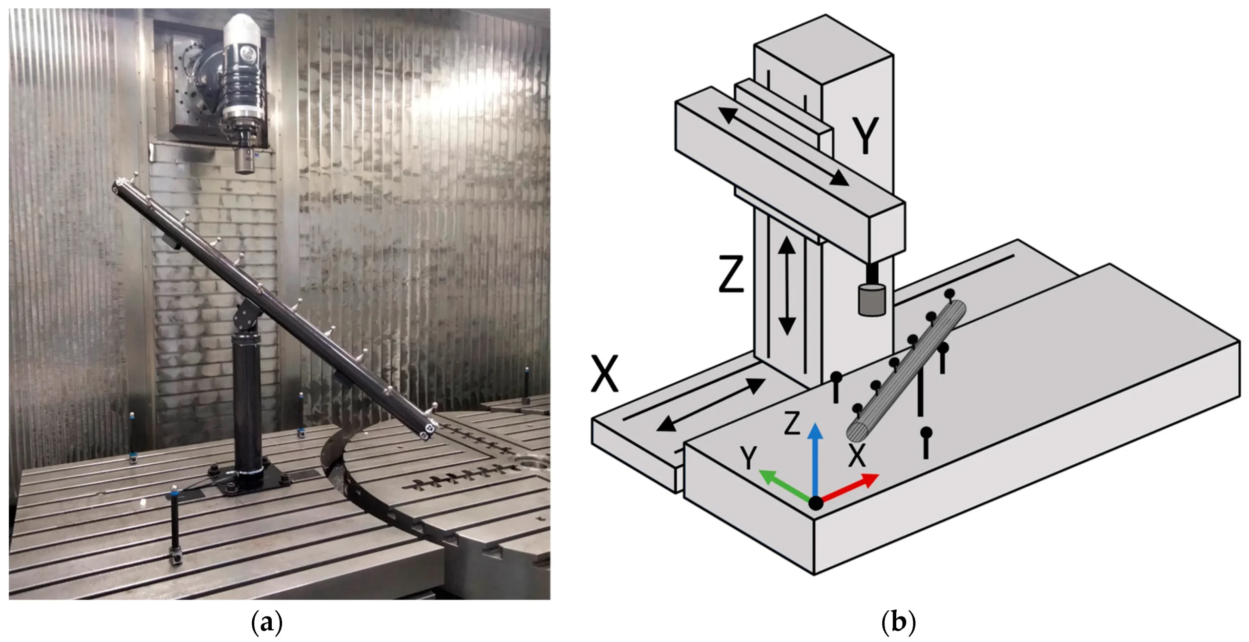
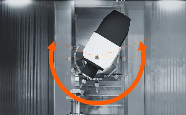
A swivel-head machine changes the cutting tool's orientation by rotating part of the spindle assembly.
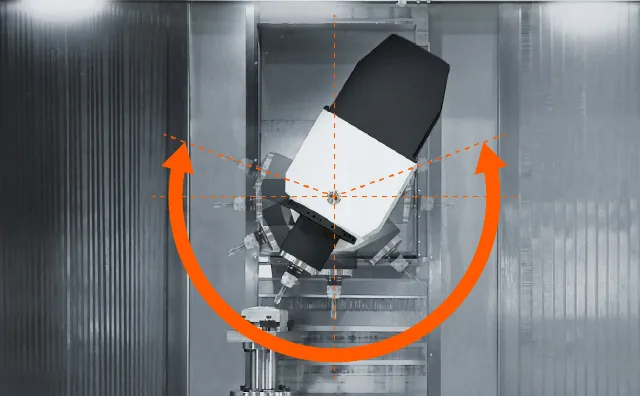
Two arrangements must be distinguished:
- Head–head: Both rotary axes act on the spindle side, allowing the workpiece to remain on a nonrotating table.
- Head–table: One rotary axis moves the spindle head, while another rotates the workpiece.
The second arrangement is commonly described as a hybrid configuration.
These differences matter because a head–table machine does not have the same workpiece movement or clearance requirements as a head–head machine.
DMG MORI identifies these distinct kinematic arrangements in its technical documentation on five-axis machining centers.
| Engineering factor | Trunnion / cradle type | Swivel-head / hybrid type | Selection implication |
|---|---|---|---|
| Rotary-axis placement | Both on the workpiece side | One or both on the spindle side | Changes relative tool–workpiece movement |
| Workpiece movement | Tilts and rotates | May rotate or remain stationary | Affects loading and clearance |
| Spindle orientation | Fixed relative to the machine structure | Articulates during positioning or cutting | Changes tool approach angles |
| Workpiece loading | Supported by the tilting rotary assembly | May use a larger main table | Check the applicable load rating |
| Work envelope | Limited by workpiece swing and tilt clearance | Limited by head movement and tool reach | Evaluate the complete setup |
| Tool accessibility | Depends on workpiece orientation | Depends on spindle-head orientation | Collision checks remain necessary |
| Rigidity | Depends on cradle, spindle, and frame construction | Depends on head, bearings, and machine frame | Neither is universally more rigid |
| Kinematic accuracy | Influenced by table-axis geometry | Influenced by head and any table-axis geometry | Calibration and verification are necessary |
How Does Machine Structure Limit Workpiece Dimensions and the Usable Work Envelope?
The usable five-axis CNC machine work envelope is not simply the space defined by the published X-, Y-, and Z-axis travels.
A machine must accommodate the workpiece throughout the required machining movements, including the space occupied by fixtures, tools, and spindle components.
This distinction becomes particularly important when a part must be machined from several orientations.
Trunnion Machines: Swept Volume and Tilt Clearance
On a trunnion machine, the workpiece and fixture move together as the rotary table tilts.
A relatively tall component may fit comfortably when upright but require additional clearance as it approaches a horizontal orientation. The fixture can also interfere with the machine structure or consume the linear-axis travel needed to reach a feature.
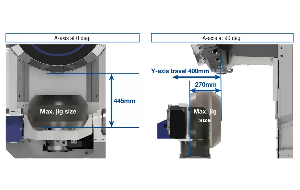
The relevant dimensions include:
- Workpiece diameter, height, and overall geometry.
- Fixture height and clamping arrangement.
- Available rotary-axis tilt.
- Workpiece swing clearance.
- Remaining linear travel at the required orientation.
Hurco's machine-selection guidance highlights a practical problem: a tall workpiece and fixture combination can exhaust the available Y-axis travel when a trunnion tilts, even though the nominal Z-axis clearance appears sufficient.
A larger trunnion is not automatically the answer. Its geometry may require longer tooling to reach small components positioned near the center of a large rotary assembly.
Swivel-Head Machines: Head Clearance and Tool Reach
Swivel-head machines have different accessibility constraints.
Because the spindle assembly changes orientation, its housing must clear the workpiece, fixture, and surrounding machine components.
As the head tilts, additional linear movement may be necessary to maintain the programmed tool position. The required travel also depends on the toolholder and cutting-tool length.
A machine with sufficient table space may therefore lack the reach needed to machine a particular sidewall or cavity.
For either architecture, manufacturers should evaluate the complete toolpath and fixture arrangement using machine-specific collision simulation or equivalent clearance verification before confirming that a component fits.
How Do Workpiece Weight and Machine Rigidity Affect Machining?
Workpiece weight affects machine selection because different configurations transmit loading through different structural components.
On a trunnion machine, the tilting assembly supports the workpiece and fixture during rotary movement. Its rated capacity, support geometry, and the position of the combined center of gravity all matter.
A swivel-head arrangement can be advantageous for heavy components when the machine supports the workpiece on a larger table without requiring its complete mass to tilt.
Published specifications illustrate why the exact machine matters.
Hurco lists a 250 kg maximum trunnion-table load for its VMX42Ui. Its VMX42SRTi, a different head–table machine, specifies a 500 kg rotary-table capacity and a 1,360 kg main-table capacity.
These figures are not a controlled comparison of equivalent machines. They demonstrate why the maximum load on a main table must not be confused with the capacity of a rotary axis.
Rigidity requires similar care. A supported trunnion and fixed-orientation spindle can create a favorable structural arrangement, but bearing design, head construction, cutting forces, and workholding determine actual deflection.
Neither architecture guarantees greater stiffness or better accuracy under every cutting condition.
How Does Five-Axis Machine Kinematics Affect Dimensional Accuracy?
Five-axis CNC machining accuracy depends on maintaining the intended position and orientation of the cutting tool relative to the workpiece.
Every machine axis contributes to that relationship. Errors in rotary positioning, axis alignment, or machine geometry can affect the location of finished features.
Gao and colleagues, in a 2023 machine-tool calibration review available through NIST, identify intra-axis, inter-axis, and volumetric errors as important categories in understanding machine accuracy.
Machine structure influences how those errors propagate, but it does not determine their magnitude by itself.
Rotary-Axis Errors and Their Dimensional Consequences
A small angular positioning error can become a measurable linear displacement at a distance from the rotation center.
For a small angular error, the approximate relationship is:

Here, $e$ represents linear displacement, $r$ is the distance from the relevant rotation axis, and $\theta$ is the angular error expressed in radians.
HEIDENHAIN provides an example involving a workpiece with a 500 mm edge length centered on a rotary table. In that geometry, a rotary positioning error of approximately two millidegrees can produce about 0.01 mm of dimensional displacement.
This illustrates why rotary-axis accuracy becomes especially important when machining features separated by substantial distances or positioned on opposing faces.
It does not establish a universal tolerance for trunnion machines.
Swivel-head and hybrid machines experience their own kinematic errors because spindle-head rotation changes the tool's position and orientation relative to the workpiece.
Calibration, Feedback and Machine Geometry
Accurate five-axis machining requires a correctly defined kinematic model.
Tool center point control helps coordinate the linear and rotary axes so that the programmed cutting-tool position is maintained as orientation changes. Its effectiveness depends on the accuracy of the machine model and the underlying axes.
Rotary-axis feedback also matters.
In a semi-closed-loop system, motor-position feedback may not directly account for errors introduced by mechanical transmission components. Direct angular feedback can measure the rotary axis itself and improve control over certain positioning errors.
Kinematic calibration helps identify deviations in axis geometry and rotation-center location. Thermal compensation may also be needed when machine geometry changes with operating temperature.
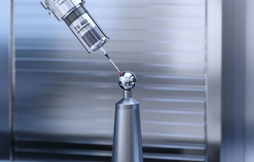
These measures improve control over specific error sources. They do not eliminate tool deflection, workpiece distortion, or every other cause of dimensional variation.
How Do Tool Access, Workholding and Machining Mode Influence the Finished Part?
The ability to orient a cutting tool favorably can influence both dimensional control and surface quality.
Approaching a deep feature from a suitable angle may permit a shorter tool assembly. Reduced overhang generally improves cutting stability by limiting deflection and vibration.
Sandvik Coromant identifies tool stick-out, gauge length, and assembly clearance as important considerations in milling performance.
Machine architecture determines which approach angles are physically available, but neither configuration guarantees short-tool access for every feature.
Workholding introduces another constraint. The fixture must support the component against cutting forces while preserving the intended datum relationships.
A single setup can reduce variation associated with repeatedly relocating a workpiece. It cannot eliminate geometric errors or deformation during cutting.
Both trunnion and swivel-head architectures may support two machining strategies:
- 3+2 indexed machining: The rotary axes establish an orientation before cutting proceeds with the linear axes.
- Simultaneous five-axis machining: Linear and rotary movements are coordinated continuously during cutting.
Indexed machining can be suitable for angled holes and multiple planar faces. Complex curved surfaces may require continuous changes in tool orientation.
The appropriate strategy depends on feature geometry, accuracy requirements, tooling, and machine capability, not simply the architecture.
How Should Manufacturers Verify Five-Axis Machining Accuracy?
Machine positioning specifications do not establish whether a finished component satisfies its engineering drawing.
Verification must distinguish between creating the required geometry and producing the specified dimensions, feature relationships, and surface conditions.
Geometry Creation and Functional Finishing
A machine may be able to reach a surface without being able to finish it to the required accuracy under the selected cutting conditions.
Function-critical features deserve particular attention, including:
- Precision bores and bearing interfaces.
- Mating and sealing faces.
- Mounting surfaces.
- Threads and accurately located holes.
- Datum-related geometric tolerances.
Tool deflection, fixture stability, thermal behavior, and cutting parameters can affect these features even when the programmed toolpath is geometrically correct.
Where necessary, additional finishing operations should be included in the manufacturing plan.
Surface roughness also requires separate evaluation. Neither trunnion nor swivel-head construction guarantees a particular surface finish.
Machine Verification and Finished-Part Inspection
Machine verification and component inspection serve different purposes.
ISO 10791-6:2014 addresses defined machine kinematic tests, including coordinated axis movements. ISO 10791-7:2020 concerns machining accuracy evaluated through finished test pieces.
These assessments provide useful information about machine performance, but they do not replace inspection against a production drawing.
Depending on the component, quality verification may include:
- Rotary-axis calibration and positioning checks.
- Workpiece probing.
- Coordinate measuring machine (CMM) inspection.
- Dimensional inspection reports.
- Surface roughness measurement.
A CMM can evaluate specified dimensions and geometric relationships, while rotary-axis tests help investigate machine positioning behavior.
The inspection method and acceptance criteria should be selected according to the actual engineering requirements.
How Does Machine Configuration Affect Total Manufacturing Cost?
The economical five-axis machining configuration is the one that can complete the required operations with acceptable setup effort, machining time, and quality risk.
Machine hourly rates alone do not determine the final unit cost.
For a trunnion configuration, fixture design, rotary clearance, loading, and tool access can influence setup and machining efficiency.
For a swivel-head configuration, head clearance, workpiece handling, available reach, and programming requirements may affect the manufacturing route.
Both arrangements share major cost drivers:
- Raw-stock dimensions and material.
- CNC programming and setup.
- Cutting tools and tool wear.
- Machining time.
- Inspection and finishing.
- Scrap or rework risk.
- Production quantity.
A configuration that reduces workpiece repositioning may lower setup effort. Yet specialized fixtures, longer cutting tools, or additional inspection could offset that benefit.
A defensible cost comparison requires the same component requirements and a realistic production plan for each candidate machine.
Which Five-Axis Machine Configuration Should an Engineer Select?
The correct configuration depends on whether the machine can accommodate the component, access its critical features, and maintain the required dimensional relationships throughout production.
A trunnion-type machine is worth evaluating for compact or medium-sized components requiring machining from multiple orientations, provided the workpiece and fixture fit within the rotary envelope and load limits.
A swivel-head or head–head machine may be more practical for certain large, heavy, or elongated components when keeping the workpiece on a larger supporting table improves feasibility.
Head–table machines provide another option when combining spindle articulation with workpiece rotation creates suitable access.
These are starting points for evaluation, not universal application rules.
Before approving a machine or supplier, engineers should verify:
- Part geometry: Can all required features be reached without interference?
- Loading: Can the relevant machine axes support the workpiece and fixture?
- Tooling: Are suitable tool lengths and approaches available?
- Accuracy: Can the machining process meet critical dimensional and geometric requirements?
- Inspection: What measurements will establish finished-part conformity?
- Production: Does the configuration support the expected quantity and manufacturing route?
A complete CAD model and engineering drawing should accompany the material specification, stock dimensions, critical tolerances, surface requirements, and quantity.
These details allow the manufacturer to evaluate machining feasibility rather than selecting equipment from general architecture descriptions alone.
Conclusion
Trunnion and swivel-head five-axis machines differ in how they position the cutting tool relative to the workpiece. That structural distinction affects usable machining space, workpiece loading, tool access, and the mechanisms through which positioning errors influence the finished part.
A trunnion configuration may suit components that fit its tilting rotary envelope. Swivel-head or hybrid arrangements may be preferable when workpiece dimensions, weight, or tool-access requirements favor another kinematic structure.
Neither approach guarantees better accuracy. Machine-specific capability, workholding, calibration, and inspection determine whether the finished component meets its requirements.
BaiChuan Precision Manufacturing advertises multi-axis CNC milling capabilities and dimensional inspection services. Engineers can submit their drawings, material specifications, tolerances, and production requirements for a manufacturability assessment and quotation.
References
1. DMG MORI. 5-Axis Machining Centers. Technical Whitepaper.
2. Metrol. 5-Axis Machining Center: Types and Features. 2024, updated 2026.
_3. Hurco. 5-Axis Machine Sizing, VMX42Ui Specifications, VMX42SRTi Specifications._
4. Gao et al. (2023). Machine Tool Calibration: Measurement, Modeling, and Compensation.
_5. HEIDENHAIN (2020). Positioning Accuracy of Rotary Axes._
6. Sandvik Coromant. Modular Solutions for CNC Tooling.
7. ISO. ISO 10791-6:2014 and ISO 10791-7:2020.
8. BaiChuan Precision Manufacturing. CNC Milling Capabilities.