
CNC milling tolerances: What does ±0.01 mm mean for a supplier's production process control?
A drawing that specifies ±0.01 mm on a milled feature raises a practical question: can the supplier hold that dimension across the intended production run, or only produce one acceptable sample? CNC milling tolerances describe permitted variation, but a machine's positioning specification does not prove that finished components will consistently meet the drawing.
For a bilateral ±0.01 mm requirement, the dimension may deviate by 10 micrometers (µm) in either direction-a total tolerance band of 20 µm. Maintaining that narrow band depends on the feature, material, workholding, cutting conditions, process monitoring, and the reliability of final inspection. Buyers should evaluate those controls before treating a supplier's precision claim as a production commitment.
What Does ±0.01 mm Mean for a CNC-Milled Feature?
A ±0.01 mm tolerance allows a specified dimension to vary by no more than 0.01 mm above or below its nominal value. For example, a hypothetical milled feature dimensioned at 50.000 ±0.010 mm has lower and upper limits of 49.990 mm and 50.010 mm. The entire acceptable size interval is 0.020 mm wide.
The callout applies to the identified dimension, not every hole, face, or relationship on the component. A locating feature may need close control while an unrelated clearance surface may not.
When invoked by the drawing or contract, general tolerance systems such as ISO 2768 address dimensions without individual tolerances; they do not make ±0.01 mm the default. Geometric dimensioning and tolerancing (GD&T) controls position, orientation, and form through separate rules and datums. Surface roughness is also distinct. A part can meet size requirements yet fail position, flatness, or surface finish.
Why Machine Accuracy Does Not Prove Production Capability
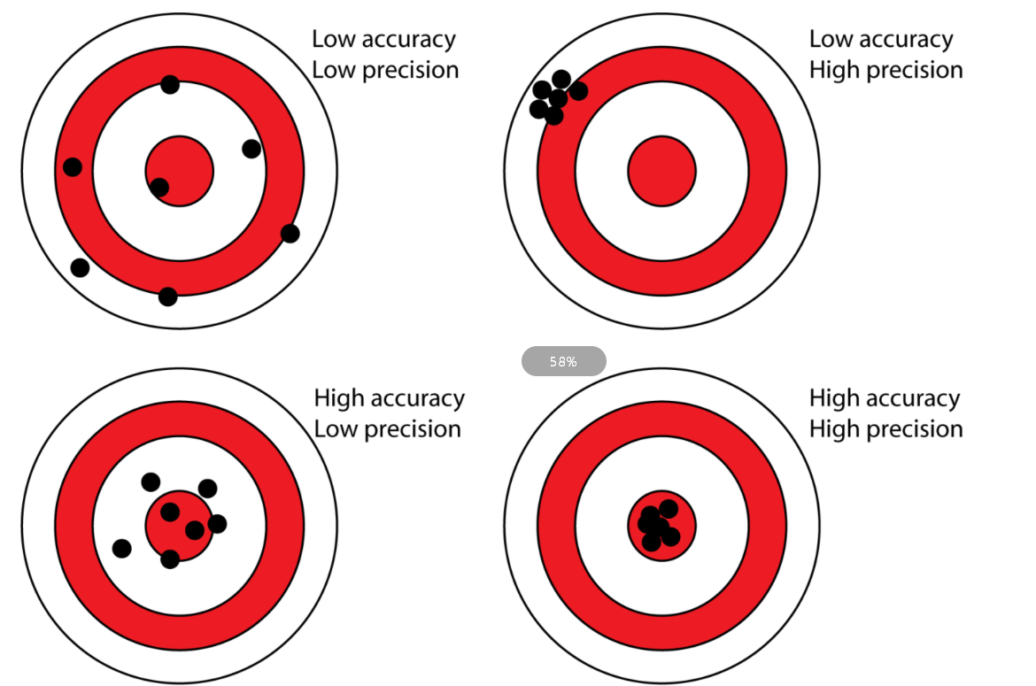
Machine accuracy and production capability measure different things. Axis positioning performance describes the machine under specified conditions; the size of a finished feature also reflects the workpiece, cutter, fixture, cutting forces, and operating environment.
A machinist may adjust offsets until an initial part measures within tolerance. As cutting continues, tool wear, material variation, temperature change, or re-clamping can shift subsequent results. That is why an accepted prototype or first article demonstrates initial conformity, not necessarily repeatability over a full batch.
Production approval needs evidence that the process remains stable and centered within drawing limits. Statistical process control (SPC) can reveal dimensional changes. With representative data and suitable assumptions, Cp and Cpk assess spread and centering against specification limits. A stable process can still produce out-of-tolerance parts.
The meaningful question is not simply whether a machine can reach a dimension, but whether the proposed manufacturing route can reproduce the required feature under real production conditions.
What Causes Dimensional Variation in Tight-Tolerance Milling?
Tight tolerance CNC milling becomes more difficult when machining forces, workholding, material behavior, or temperature changes move a feature relative to its intended geometry. The dominant risk depends on the component rather than the tolerance number alone.
Fixture, Tooling and Feature Geometry
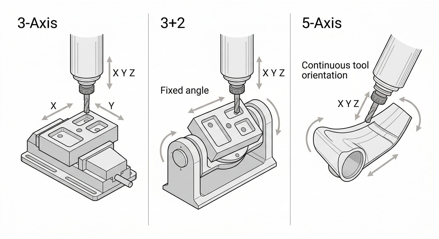
Workholding must locate the part against appropriate datums without distortion. Excessive thin-wall clamping may change its shape, which can move again after release. Multiple setups add locating variation, especially across setup boundaries.

Cutting tools also bend under load. Long tool overhangs, deep pockets, vibration, and changing cutter engagement can affect the final surface. Tool wear gradually changes the effective cutting edge, making a dimension that passed early in production drift toward a specification limit. The fixture, toolpath, cutting conditions, and wear-response plan should therefore be reviewed together.
Material Behavior and Thermal Stability
Aluminum is often straightforward to machine, but its thermal expansion and the movement of thin or stress-sensitive features can affect precision measurements.
For an illustrative calculation, aluminum's approximate expansion coefficient near 20°C is 23.1 × 10⁻⁶/K. A freely expanding 100 mm length undergoing a 5°C rise would change by approximately 0.01155 mm, or 11.55 µm-greater than one side of a ±0.01 mm tolerance band.
This is a simplified physical example, not an estimate of BaiChuan's machining error. Actual behavior depends on the alloy, geometry, temperature distribution, reference condition, and any compensation applied.
Some stainless steels present work-hardening, cutting-force, and tool-wear challenges. Titanium requires careful management of cutting heat and tool condition. Certain engineering plastics are especially sensitive to clamping, temperature, and dimensional change over time. None is automatically unsuitable for a tight tolerance; feasibility depends on the exact grade, feature, process plan, and inspection conditions.
How Does a Supplier Control ±0.01 mm from Setup Through Finishing?
A reliable supplier controls the sources of variation before cutting, measures important changes during production, and verifies the finished part. These activities serve different purposes; final inspection alone cannot make an unstable process consistent.
Establish the Setup and Finishing Strategy
The starting point is a controlled drawing: its revision, critical features, datum references, material, and final condition. The manufacturing team can then select a workholding arrangement, tool access strategy, and sequence that protects the dimensions most important to assembly.

Roughing removes most unwanted material, but it can introduce heat and release internal stresses. For sensitive features, the process may leave an appropriate finishing allowance and use a later finishing operation after conditions stabilize. Machine readiness, tool setting, and fixture repeatability matter because the final pass cannot reliably correct every upstream error.
Monitor Drift and Correct the Process
In-process metrology, including on-machine probing where suitable, can check feature locations or dimensions before more parts are completed. Tool-setting systems and wear monitoring can inform offset adjustments. Thermal error compensation may also be useful when the machine and process support it.
Adjustments should follow meaningful measured changes. A reaction plan addresses trends toward limits and nonconforming results. Records help distinguish isolated issues from recurring problems.
| Manufacturing stage | Main variation risk | Practical control | Evidence for the buyer |
|---|---|---|---|
| Drawing and setup | Wrong datum or inconsistent location | Confirm critical features, offsets, and fixture arrangement | Approved drawing and setup plan |
| Roughing and finishing | Deflection, heat, or material movement | Control cutting strategy and finishing allowance | First-piece dimensional results |
| Production monitoring | Tool wear or gradual dimensional drift | Appropriate probing, gauges, and correction rules | In-process measurements and actions |
| Final inspection | Undetected nonconformance or measurement uncertainty | Feature-appropriate calibrated measurement | Agreed dimensional inspection report |
These are general engineering controls. Their implementation must be established for the particular supplier and part; the table does not assert that BaiChuan operates every method listed.
How Can Inspection Verify ±0.01 mm with Confidence?
Verification requires a measurement method capable of assessing the specified feature with uncertainty appropriate to its tolerance. A coordinate measuring machine (CMM) can be valuable, particularly for complex geometry and relationships to datums, but the word CMM alone is not proof of suitable measurement capability.

First-Article Approval Versus Ongoing Production Evidence
First-article inspection checks whether an initial manufactured part conforms to the drawing under the selected setup and process. In-process checks look for changes as production continues. Final inspection provides the agreed acceptance evidence for shipment. Each answers a different question.
For a recurring batch, the inspection plan should identify critical characteristics, measurement methods, sampling or coverage requirements, and actions following nonconformance. SPC data and, where justified, process-capability analysis can help evaluate ongoing performance. A first-article pass should never be presented as a substitute for those production controls.
Measurement Uncertainty and Final Acceptance
The instrument depends on the feature. A calibrated micrometer or gauge may suit an accessible linear dimension; a CMM may suit complex datum-related geometry. Probe qualification, fixtures, calibration, cleanliness, and workpiece temperature influence the result.
Measurements close to a tolerance boundary require particular care. ISO 14253-1 addresses conformity decisions that account for measurement uncertainty. Buyers and suppliers should agree on the relevant acceptance rules before disputes arise over a borderline dimension. Instrument resolution-the smallest displayed increment-is not the same as total measurement uncertainty.
Dimensional size, geometric form or position, and surface roughness must also be checked according to their own drawing requirements. Passing a size measurement does not automatically approve a sealing face, bearing seat, or aligned hole pattern for its intended function.
When Is ±0.01 mm Necessary, and What Does It Change in Cost?
A ±0.01 mm tolerance is justified when the controlled dimension protects an actual functional requirement; applying it indiscriminately can increase manufacturing effort without improving performance. Locating bores, bearing interfaces, and mating features may need closer control than cosmetic edges or non-critical clearance surfaces.
The decision should consider the assembly, datum structure, tolerance stack-up, and final condition of the component. Creating the basic milled shape is not the same as completing every functional feature. A bore, mating face, or thread may require a specific finishing operation, while surface treatment may affect the dimensions to be verified on the finished part.
Tighter requirements can change fixtures, programming, tooling, finishing, temperature management, inspection time, and rework exposure. Material, geometry, quantity, and documentation affect total cost. Specify the tolerance function requires, not the smallest number a supplier advertises.
What Evidence Should Buyers Request from a Tight-Tolerance CNC Milling Supplier?
A credible supplier should be able to explain how a critical dimension will be produced, monitored, and accepted-not simply state that ±0.01 mm is achievable. The review should begin with a drawing that identifies the relevant features and datums, together with material, quantity, finishing, and inspection requirements.
Before approving production, buyers should establish:
- Feature-specific feasibility: Which dimensions can be held by the proposed route, and what geometry or material limitations apply?
- Production controls: How will setup, tools, wear, temperature, and changes between operations be managed?
- Inspection method: Which measuring system and acceptance rules will apply to the critical characteristics?
- Documented evidence: What first-article records, production checks, final reports, or capability data are appropriate for the order?
- Nonconformance response: How will suspect parts be contained, evaluated, and corrected?
BaiChuan Precision Manufacturing's published CNC milling information describes ±0.01 mm as an available tight-tolerance capability when required, not a routine guarantee for every feature. A project-specific commitment should follow review of the actual drawing and manufacturing conditions.
Buyers can provide their critical dimensions, material, quantity, and inspection expectations for a manufacturability assessment and quotation.
Frequently Asked Questions
Can a CNC milling supplier confirm ±0.01 mm capability before reviewing the actual part drawing?
Not reliably for every application. Feasibility depends on the controlled feature, geometry, material, datum structure, manufacturing route, quantity, and inspection requirements. A supplier may advertise tight-tolerance capability but should confirm the specific application after reviewing the drawing.
Does a ±0.01 mm requirement need to be verified after anodizing, plating, or another finishing process?
If the drawing specifies the dimension in the finished condition, verification must reflect that condition. Some treatments can affect final dimensions or surface characteristics. The drawing and purchase requirements should clearly identify when measurements apply.
Does every ±0.01 mm feature require inspection on every production part?
Not automatically. Inspection frequency depends on feature criticality, process stability, customer requirements, and the agreed quality plan. Some applications require complete inspection, while others can use justified sampling with suitable process controls.
Conclusion
A supplier's ±0.01 mm claim becomes meaningful when it is connected to a specific functional feature, a feasible manufacturing route, stable process controls, and trustworthy inspection evidence. Engineers should specify that level of precision where function demands it, while buyers should judge capability from the actual production and verification plan rather than a machine rating or isolated sample.
For a BaiChuan project, the practical next step is a review of the drawing, material, critical dimensions, production quantity, and acceptance requirements before confirming manufacturing feasibility.
References
1. ISO 2768-1:1989 - General Tolerances - ISO, 1989.
2. ASME Y14.5 - Dimensioning and Tolerancing - ASME, 2018 (R2024).
3. Machine Tool Calibration: Measurement, Modeling, and Compensation - Gao et al., 2023.
_4. Detection of Workpiece Temperature - ZEISS Metrology._
5. When Do I Probe? - Renishaw.
6. What Is Process Capability? - NIST/SEMATECH.
7. ISO 14253-1:2017 - Measurement and Conformity - ISO, 2017.
8. CNC Milling Capabilities - BaiChuan Precision Manufacturing.