Introduction
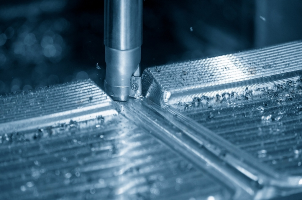
For the best quality and performance of products in manufacturing applications, maintaining accurate surface roughness levels is essential. Understanding the relevance of the surface roughness chart is crucial since surface finish has a crucial impact on a product's functioning and longevity. Rough surfaces often include imperfections that act as nucleation sites for damage, corrosion, and subsequent material deterioration, making them more prone to rapid wear and greater friction. On the other hand, the proper amount of roughness may encourage the necessary adhesion, highlighting the need for accuracy in surface finishing. This in-depth guide on surface roughness is ideal for you if you want to improve the quality and functionality of your produced goods.
Because surface abnormalities may serve as nucleation sites for fractures and corrosion, surface roughness is a good indicator of mechanical component performance. It is a well-known fact in tribology that rough surfaces, as opposed to smooth ones, display quicker wear and higher friction coefficients. Controlled roughness is necessary in certain applications, nevertheless, to promote adhesion for cosmetic finishes like plating, powder coating, or painting. In addition to improving appearances, a well-done surface finish guarantees that the product will function as intended. It's crucial to have a thorough grasp of surface roughness if you want to master the technique of producing the perfect surface finish and manufacturing procedures for your products. We will provide you with all the crucial information you want on the subject in this post.
Surface Roughness Basics
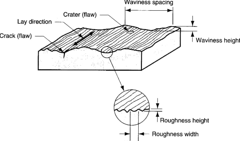
Surface finish refers to the procedures used to modify the surface of a metal by taking away, adding, or rearranging material. It offers a thorough assessment of the surface texture of a product using four distinguishing factors: surface roughness, waviness, flaws and lay. A surface is categorized as rough or smooth based on the magnitude of these variances.
Components of Surface Roughness
Surface finish comprises four integral components: lay, waviness, flaws, and roughness. Although the term is often used interchangeably with surface roughness in machine shops, each facet carries its unique importance. Surface roughness, the most commonly referenced characteristic, plays a pivotal role in manufacturing, but understanding all four components is essential for comprehensive quality control and product performance.
1. Roughness.
Surface roughness, frequently abbreviated as "roughness," is a paramount component of surface finish. It quantifies the irregularities across a material's surface, determining its overall texture. In many machining discussions, when "surface finish" is mentioned, it primarily alludes to surface roughness. This aspect measures the small, finely spaced deviations from the nominal surface, a result of both material characteristics and the manufacturing process. These deviations distinguish between a rough or smooth surface – significant deviations indicate roughness, while minor ones indicate smoothness. In the domain of surface metrology, roughness is often envisioned as the high-frequency, short-wavelength segment of a measured surface. Furthermore, it's commonly expressed using a single numeric parameter, Ra, which signifies the arithmetic average of surface heights measured across a surface. Detecting and assessing surface roughness is achieved with a profilometer, a surface profile measuring instrument, which calculates the average height of part roughness irregularities concerning a mean line. Understanding and controlling surface roughness is pivotal in achieving desired product quality, functionality, and precision in manufacturing processes.
2. Lay
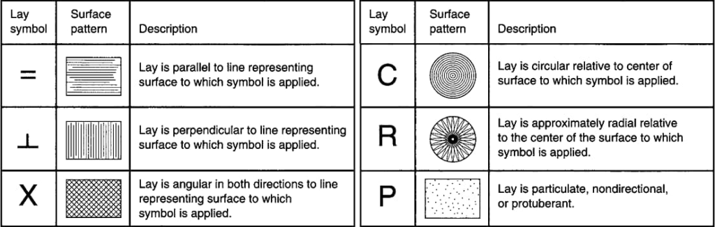
Lay, an integral aspect of surface finish, defines the predominant direction or pattern of surface texture. It is the result of the specific manufacturing methods employed to create the surface, often influenced by the action of a cutting tool. Lay patterns vary, and machinists often discern them through methodological approaches. These patterns encompass parallel, perpendicular, radial, multi-directional, circular, crosshatched, and isotropic (non-directional) orientations. Designers use specific symbols to communicate and specify these various lay patterns, as depicted in the accompanying chart, offering a comprehensive understanding of this crucial element within surface finish.
3. Waviness
Waviness, an integral facet of surface finish, pertains to surface deviations that exhibit greater spacing than the length of surface roughness. These periodic irregularities are noticeable but distinct from flatness faults, characterized by their larger yet still minor, regular, and closely spaced flaws. Common sources of waviness include warping due to heating and cooling and machining issues arising from chatter or deflection during the manufacturing process.
Waviness is evaluated over an assessment length, from which a waviness profile is constructed, effectively excluding surface anomalies attributed to roughness, flatness, or shape changes. The waviness spacing (Wsm) is determined by the peak-to-peak spacing of these waves, while the wave height is represented by the average waviness (Wa) or total waviness (Wt) parameters. While waviness requirements are less common compared to roughness criteria, they hold particular significance for specific components, such as bearing races or sealing surfaces, where precision in waviness is of paramount importance.
4. Flaws
Flaws encompass random irregularities stemming from machining or production processes like molding, drawing, or forging. These imperfections, ranging from scratches and cracks to holes and inclusions, impact both surface texture and integrity.
Measuring Surface Roughness
Surface roughness assessment depends on diverse measuring systems. The primary parameter, Ra, signifies the arithmetic average of surface heights across a given surface. It's featured in the Ra surface finish chart. Measuring systems encompass direct, non-contact, comparison, and in-process methods. These systems are instrumental in determining the relative smoothness of a surface's profile and upholding quality standards in manufacturing.
I. Direct measurement methods/Contact Method
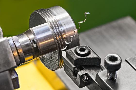
Using a stylus to detect surface texture is a direct measuring method for surface roughness. Machinists use registered profiles to calculate the surface roughness characteristics when they draw the stylus perpendicularly over the surface. However, this contact approach has the potential to cause micro-scratches on tested surfaces and interrupt the machining process. Despite providing accurate readings, it could be practical owing to the possibility of surface degradation. To balance the necessity for precision with the possibility of surface modification during measurement, the procedure needs considerable thought.
II. Non-contact methods
Non-contact methods in surface roughness measurement provide alternatives to stylus-based techniques, employing light or sound for precision assessment. Optical instruments like white light and confocal microscopes replace the stylus, utilizing distinct principles for measurement. Moreover, structured light, electrical capacitance, electron microscopy, interferometry, confocal microscopy, focus variation, atomic force microscopy, and photogrammetry are among the non-contact methodologies available. Ultrasonic pulses are delivered to the surface, and altered sound waves reflect back to derive roughness parameters. Light-based methods project lasers onto surfaces, assessing roughness by measuring the intensity of reflected light – greater roughness results in greater light dispersion and lower reflected light intensity. These non-contact approaches offer precision without surface contact and potential damage, making them valuable tools in surface metrology.
III. Comparison Method
Surface roughness analysis employs surface roughness samples made using the same tools and processes as the subject material. Manufacturers compare these samples to surfaces with established roughness characteristics using their visual and tactile senses. This method works well for non-critical applications but is less accurate than other, more objective assessment approaches due to its subjective character.
IV. In-process Method
The in-process method, illustrated by inductance, makes use of magnetic materials for on-the-fly assessment of surface roughness. The inductance pickup measures the distance to the surface using electromagnetic energy, providing parametric values necessary for comparing roughness metrics. This method provides continuous surface monitoring throughout milling or other processes, giving operators useful feedback. Additionally, the in-process method frequently produces more accurate findings than competing techniques because it can evaluate surfaces under settings that are more like actual application scenarios. This improves manufacturing precision.
Surface Roughness Parameters
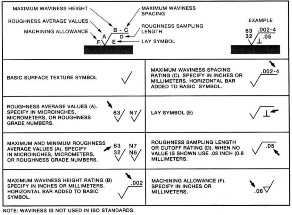
When exploring machining surface finish symbols, you'll encounter a diverse range of abbreviations such as Ra, Rsk, Rq, Rku, Rz, and more, all serving as units for quantifying surface finish. As you delve into surface roughness charts, you'll observe various units and abbreviations, albeit with some variations depending on nations and organizations. Among the commonly employed surface roughness symbols and parameters, four stand out for their significance in quality control and manufacturing processes.
1. Ra – Average Surface Roughness
Ra, often referred to as the Center Line Average or Arithmetic Average, calculates the average roughness between a roughness profile and the mean line. This widely recognized parameter in surface finish measurement represents the arithmetic average of surface heights measured over a given area. Despite its common usage, it's important to note that different surface roughness profiles sharing the same Ra value may exhibit varying behaviors, necessitating the consideration of additional surface roughness parameters for a comprehensive evaluation.
2. Rz (Average Maximum Height of the Profile)
Rz, often referred to as the Average Maximum Height of the Profile, measures the average values of the five largest discrepancies between peaks and valleys across a surface. This parameter employs five sampling lengths to calculate this average, offering a more comprehensive assessment compared to Ra. Unlike Ra, which can be insensitive to certain extremes, Rz helps eliminate potential sources of error from the measurement process. As one of the most commonly used international abbreviations for surface finish evaluation, Rz plays a significant role in achieving more precise results.
3. Rmax (Vertical Distance from Peak to Valley)
Rmax, focusing on the vertical distances between a surface's peaks and valleys, excels in identifying anomalies like burrs and scratches, which might go unnoticed using the Ra surface finish chart. Although the Ra chart may not clearly indicate such abnormalities, Rmax is notably sensitive to them. When pinpointing the maximum roughness on a surface, Rmax proves valuable, and various measuring methods can be employed to further refine its assessment. This parameter plays a vital role in achieving a more detailed evaluation of surface irregularities.
4. RMS-Root Mean Square Roughness
A measurement known as RMS, or Root Mean Square Roughness, determines the root mean square of a surface's peaks and valleys. RMS gives a more precise evaluation than Rz roughness since it makes use of more mathematical points on the surface. RMS is frequently a trustworthy option if you want to avoid computing Ra. The numbers are squared, their average is calculated, and the square root of that average is found in order to compute RMS. RMS establishes the average curve using a sine wave, enabling the measurement of the average departure from the mean line. This approach provides a more thorough study of surface roughness.
Classification of Surface Roughness
Surface roughness assessment encompasses three categories of methods: area, profiling, and microscopy, each requiring distinct equipment and techniques.
Profiling techniques employ high-resolution probes for surface measurement, akin to the sensitivity of a phonograph needle. Standard CNC probes may not offer the same effectiveness in this process.
Area techniques are employed to measure a finite surface region, delivering a statistical average of its peaks and troughs. These methods encompass optical scattering, ultrasonic scattering, capacitance probes, and more. Automation and implementation are simplified with area techniques, making them valuable in surface roughness assessment.
Microscopy techniques rely on contrast measurements to provide valuable insights into surface peaks and troughs. These qualitative methods enable machinists to scrutinize surface finish in great detail. However, their limited field of view can be a constraint, as electron microscopes work on a tiny scale, allowing observation of only a small portion of the surface at a time. As a result, establishing average roughness parameters often necessitates multiple scans.
Interpretation of Surface Roughness
An important factor in manufacturing is surface roughness interpretation since it has a direct impact on the performance and quality of the products. Below are two helpful resources—the Surface Roughness Conversion Chart and the Surface Roughness Cheat Sheet—that may be used to help with this interpretation. These materials provide an extensive comparison of several surface roughness scales used in manufacturing operations.
Surface Roughness Conversion Chart
The chart includes essential abbreviations, such as Ra (Roughness Average), RMS (Root Mean Square), CLA (Center Line Average), Rt (Roughness Total), N (New ISO Grade Scale Numbers), and Cut-off Length (Length Required for Sample). These abbreviations are vital for the precise measurement and assessment of surface finishes.
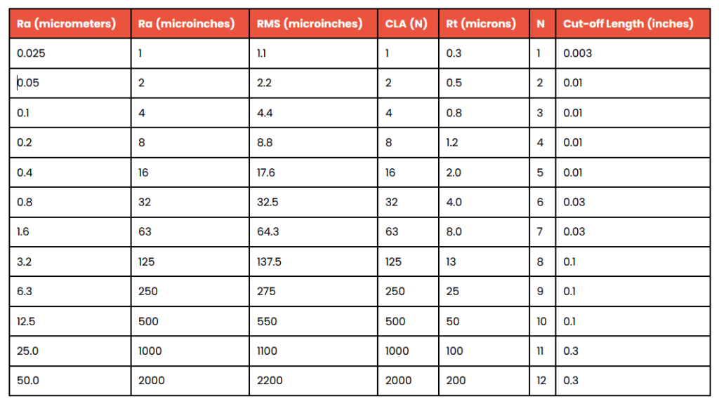
Typically, surface finish is measured in micrometers or microinches, with a smaller value indicating a finer surface polish. This measurement directly influences the surface quality of machined components. For example, a part with a micrometers rating of 12.5 or a microinches rating of 500 implies a rough and low-grade surface, typically resulting from coarse feeds and heavy cuts. On the other hand, a micrometers rating of 0.8, equivalent to a microinches rating of 32, signifies a high-quality machining surface finish that necessitates stringent control conditions. This finish is particularly suitable for components not subjected to continuous motion or heavy loads.
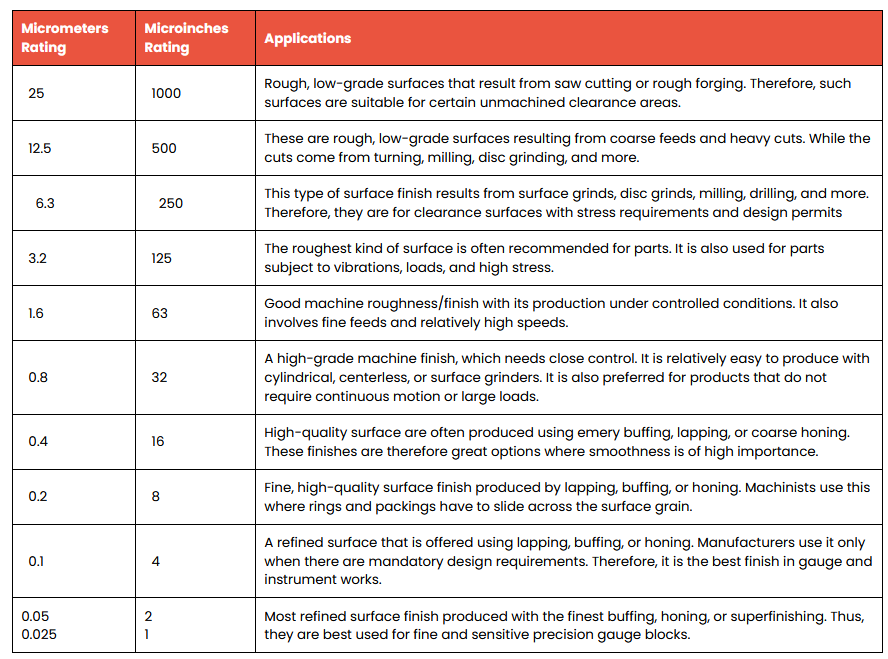
Surface Roughness Cheat Sheet
The Surface Roughness Chart Cheat Sheet is a valuable resource for understanding a variety of surface finishes, making it easier to explore available options and make informed decisions.
Importance of Surface Roughness
Surface roughness is a critical factor in determining how a product interacts with its environment, with far-reaching implications for performance and durability in various engineering applications. Rough surfaces exhibit faster wear and higher friction coefficients compared to smoother surfaces. Surface roughness serves as a reliable predictor of mechanical part performance since imperfections act as nucleation sites for breakage or corrosion. Conversely, controlled roughness can promote desirable adherence.
Engineers and manufacturers must consistently maintain surface roughness to ensure the production of uniform processes and reliable goods. The surface finish not only enhances electrical conductivity, reduces friction, and bolsters resistance to wear, corrosion, and chemicals but also adds an aesthetic appeal to products. It facilitates the adhesion of coatings and paints, making finishing methods the preferred means to achieve the desired surface finish in machined or manufactured goods. Surface measurements are indispensable for maintaining manufacturing control, making surface engineering a crucial aspect of production.
Conclusion
In contemporary manufacturing, achieving accurate surface roughness may be expensive and difficult. For surface finishing operations to provide the appropriate finishes on produced components, the most efficient approach is needed. A component's surface finish is crucial since it frequently affects the functionality and durability of designed parts. Surface finishes are influenced by the manufacturing process; very smooth surfaces may call for additional steps like grinding or polishing, which raises the cost of production. To strike a balance between quality and cost-effectiveness, engineers and designers should work to establish roughness criteria that correspond with the primary production method. An experienced technical team can assist you in navigating the complexity of surface finishing, from design input through post-processing, to achieve the best results for your goods. Please get in touch with us for assistance if you run into any machining-related problems.