Chip control is one of the most overlooked yet crucial aspects of CNC turning. Every machinist understands that producing a part with the correct dimensions is only half the challenge. The other half lies in managing the chips produced during cutting. Poor chip control can lead to tool breakage, scratched surfaces, and even operator hazards when sharp, tangled chips are thrown from the machine. In high-volume or automated setups, uncontrolled chips can jam the toolpath, interrupt cycles, and reduce productivity significantly.

Strategies for Managing Chip Control
This article explores how chip formation occurs, why difficult materials behave the way they do, and the proven methods, ranging from tool geometry and chip breaker design to process monitoring, that help achieve stable, predictable chip control in CNC turning.
Fundamentals of Chip Formation
Chip formation is a natural outcome of material removal in CNC turning. When the cutting tool engages with the workpiece, a thin layer of material is sheared off under extreme pressure and temperature. The way this material deforms and separates defines the type and shape of the chip. Proper understanding of this process is vital because chip behavior directly affects tool wear, surface finish, and machining stability.
During cutting, the material ahead of the tool’s cutting edge deforms plastically along a narrow zone known as the shear plane. The angle and condition of this plane depend on factors such as tool geometry, feed rate, cutting speed, and the material’s mechanical properties. A higher shear angle generally produces thinner chips, reducing cutting forces and heat generation, while a lower shear angle tends to create thicker, harder-to-break chips.
Role of Shear Plane, Cutting Speed, and Feed Rate
The shear plane acts as the main deformation zone where metal flow occurs. Its behavior is strongly influenced by cutting parameters:
- Cutting speed: Increasing speed can improve chip flow by reducing friction, but excessive speed may generate more heat, softening the tool and reducing chip control.
- Feed rate: Higher feed rates increase chip thickness and the likelihood of segmented or curled chips, improving breakability. However, if the feed is too low, chips become long and continuous.
- Depth of cut: A deeper cut increases chip volume and can raise cutting temperature, demanding efficient chip evacuation.
Balancing these parameters helps control chip morphology without sacrificing dimensional accuracy or tool life.
Types of Chips in Metal Cutting

Chips are broadly classified into three types based on how the material separates:
- Continuous chips: Produced in ductile materials like titanium or stainless steel under stable cutting conditions. While they offer smooth surfaces, they often entangle with the tool or workpiece, posing a safety hazard.
- Segmented (serrated) chips: Common in hard-to-cut alloys such as Inconel. The material deforms in cycles, creating small cracks that form separate chip segments. These chips improve heat dissipation and are easier to manage.
- Discontinuous chips: Typically seen when cutting brittle materials or under poor cutting conditions. They are formed when the material fractures irregularly, often causing rough surfaces and vibration.
Challenges in Turning Difficult Materials
Machining difficult-to-cut materials presents a unique set of challenges that go far beyond simple tool wear. These materials are chosen for their strength, heat resistance, and corrosion resistance, which make them ideal for aerospace, energy, and medical components. However, the same properties that make them valuable also make them problematic for machines. The chips they produce are often long, continuous, and difficult to evacuate, while heat and friction quickly degrade the tool’s cutting edge. Understanding the specific causes behind these issues is essential for selecting the right chip control strategy.

Material Properties that Cause Chip Problems
The main reason chip control becomes difficult is the material’s inherent mechanical and thermal characteristics. Most high-performance alloys have high tensile strength and work harden easily, meaning the material’s hardness increases as it deforms during cutting. This makes the cutting process progressively more demanding.
Additionally, many of these materials have low thermal conductivity, which prevents heat from escaping through the chip. As a result, most of the generated heat remains concentrated near the cutting edge, accelerating tool wear and affecting chip morphology. The combination of high strength, poor heat dissipation, and a strong tendency to harden under stress creates a perfect storm for unstable chip formation.
Common Long-Chipping Alloys
Long-chipping materials are those that resist chip segmentation during cutting. These typically include:
- Titanium alloys (Ti-6Al-4V and similar grades): Known for excellent strength-to-weight ratio and corrosion resistance, but notorious for generating continuous, spring-like chips that are hard to break.
- Inconel and other nickel-based superalloys: These materials retain strength at high temperatures, making them ideal for turbine and engine parts. However, they work hard rapidly and produce serrated chips that are tough on cutting tools.
- Austenitic stainless steels (e.g., 304, 316): They have high ductility and low thermal conductivity, resulting in long, stringy chips and significant tool pressure during turning.
Each of these alloys requires specialized tooling and parameter optimization to maintain chip control and prevent thermal overload.
Titanium Alloys: Toughness and Poor Heat Dissipation

Titanium is often described as a “heat trap.” During machining, nearly 80 percent of the cutting heat stays at the tool–chip interface because titanium cannot conduct heat away efficiently. This localized heat softens the cutting edge and promotes adhesion between the chip and tool, leading to built-up edge formation. The chips produced are continuous and tightly curled, which can wrap around the tool or part if not managed properly. Using sharp tools with positive rake angles and adequate chip breakers is critical when machining titanium to maintain short, controllable chips.
Inconel and Superalloys: Work Hardening and High Cutting Temperatures

Nickel-based alloys such as Inconel behave differently from titanium. They generate high friction during cutting, which causes the surface layer to harden rapidly. As the tool passes over this hardened layer, cutting forces increase, producing high stress on the tool and uneven chip segmentation. These alloys also retain their strength even at elevated temperatures, making heat control extremely difficult. Segmented chips form due to cyclic shear banding, but without proper geometry or coolant delivery, these segments can fuse together and cause chip flow instability.
Typical Chip Shapes and Their Machining Risks
In practical operations, chip shape is an immediate indicator of machining health. Continuous, ribbon-like chips signal stable cutting but poor chip control. Helical or snarled chips often point to insufficient chip breaking, while segmented or comma-shaped chips indicate ideal chip control.
Uncontrolled chips can lead to:
- Entanglement: Chips wrap around the tool or spindle, risking machine stoppage.
- Built-up edge: Material adhesion on the cutting edge alters geometry and reduces surface quality.
- Accelerated tool wear: Excessive rubbing and heat shorten tool life.
- Surface defects: Scratches, scoring, and uneven finishes due to chip drag.
Recognizing these patterns helps machinists adjust their parameters or tooling before major issues arise.
Effective chip control in difficult materials requires balancing several competing factors: tool strength, temperature, and chip evacuation. By analyzing chip behavior and material response, engineers can develop cutting conditions that not only improve tool life but also ensure safe, predictable performance.
Chip Breakers and Tool Geometry Design
Chip breakers and tool geometry play a decisive role in controlling chip shape, direction, and flow during CNC turning. They determine how the material deforms and fractures as it leaves the cutting zone. For difficult materials such as titanium and Inconel, even small adjustments in geometry can mean the difference between continuous chip formation and clean, segmented chips. Well-designed chip breakers not only improve safety and surface finish but also extend tool life by reducing thermal and mechanical loads.

Standard Chip Breaking Function in Lathe
When the tool engages with the workpiece, the chip slides along the rake face. The chip breaker interrupts this flow, forcing the chip to curl and fracture into shorter segments. The degree of chip curling depends on the geometry of the breaker, feed rate, and material ductility. A properly matched combination of these factors ensures chips are compact, easy to evacuate, and free from entanglement.
Purpose of Chip Breakers
Chip breakers are primarily used to manage chip formation and improve cutting efficiency. Their objectives include:
- Breaking continuous chips: Prevents long ribbons from wrapping around the part or tool.
- Reducing cutting forces: By controlling chip flow and curling, chip breakers minimize resistance between the chip and rake face.
- Enhancing heat control: Fractured chips carry away heat more effectively than continuous ones, reducing temperature at the cutting edge.
- Protecting the operator and machine: Shorter chips are safer and easier to remove automatically, reducing manual intervention.
The overall aim is to achieve a controlled chip shape that balances tool life, machining stability, and part quality.
Types of Chip Breaker Designs
Chip breakers vary in shape depending on the intended cutting condition, feed rate, and workpiece material. The three main types are:
- Groove-type chip breakers: Feature a shallow groove near the cutting edge. These are effective for light to medium feeds, providing moderate chip curling. Commonly used in finishing operations where surface quality is important.
- Step-type chip breakers: Include a step or ridge that causes the chip to curl sharply and break. They are ideal for medium to heavy feeds and are often used in roughing applications where higher material removal rates are required.
- Wavy or sinusoidal designs: Use alternating grooves and ridges to vary chip curvature, improving breakability under unstable cutting conditions. They are particularly effective for alloys with inconsistent ductility, such as certain Inconel grades.
Each type must be paired with the correct feed and depth of cut. A mismatch can lead to premature tool wear or excessive chip buildup.
Key Parameters in Tool Geometry
Beyond chip breakers, several geometric parameters influence chip formation and tool performance. The most critical are rake angle, clearance angle, nose radius, and edge preparation.
- Rake angle: Determines how easily the chip flows across the tool. A positive rake angle reduces cutting force and improves chip flow, but may weaken the cutting edge. A small or negative rake angle strengthens the edge but increases cutting forces, often used in hard or abrasive materials.
- Clearance angle: Prevents rubbing between the tool flank and workpiece. Insufficient clearance causes heat buildup and poor surface finish, while too much clearance weakens the cutting edge.
- Nose radius: A larger nose radius distributes cutting forces and improves surface finish, but excessive size may cause chatter. Smaller radii help in sharper chip control during fine turning.
- Edge preparation: Includes honing, chamfering, or coating of the cutting edge to prevent micro-chipping and enhance tool stability. Proper edge preparation is critical in machining superalloys that tend to form built-up edges.
Influence on Performance
The right combination of geometry and chip breaker design ensures stable cutting behavior. Proper chip breaking improves safety by preventing hot, sharp chips from scattering. It also enhances tool life by maintaining a consistent contact area and reducing frictional heat. From a surface finish perspective, consistent chip evacuation prevents re-cutting of chips, which could otherwise mar the surface.
Additionally, optimized tool geometry lowers spindle load and vibration, which benefits both the part quality and machine longevity. These factors are especially vital in long production runs or unattended machining operations, where any inconsistency in chip control can lead to downtime.
Process Parameter Optimization for Chip Control
Even with the best tool geometry and chip breaker design, poor control of process parameters can quickly lead to long, tangled chips and erratic cutting behavior. The way cutting speed, feed rate, and depth of cut interact determines how chips curl, fracture, and evacuate from the cutting zone. Proper parameter selection is essential for difficult materials, where minor changes can shift chip morphology from stable to unmanageable. The goal is to tune these parameters to promote chip segmentation while maintaining tool stability and consistent surface finish.

Effect of Cutting Parameters on Chip Formation
Cutting parameters directly influence chip thickness, temperature, and flow. These relationships are especially sensitive in tough materials that generate high heat and resist plastic deformation.
- Cutting speed: Increasing speed tends to reduce cutting forces and improve chip flow by lowering contact time between chip and tool. However, excessive speed raises temperature and may cause tool softening or built-up edge formation.
- Feed rate: Higher feed rates increase chip thickness, promoting segmented or curled chips that are easier to break. Too low a feed rate results in thin, continuous ribbons that are difficult to control.
- Depth of cut: A deeper cut raises the volume of material removed per pass, creating thicker chips and higher cutting loads. While it can help break chips more effectively, it also accelerates heat generation and wear.
An optimal combination balances heat control, chip size, and tool load. Continuous monitoring and small incremental adjustments help maintain this equilibrium during production.
Tool Wear and Chip Morphology Trends
As a cutting tool wears, the chip formation process changes. A sharp edge cuts cleanly and allows predictable chip curling, while a worn edge causes higher friction and inconsistent chip flow. In turning operations on alloys like titanium or Inconel, tool wear often results in thicker, serrated chips due to increased contact pressure. This leads to more heat and vibration, which further degrade the tool.
Monitoring chip color and shape gives visual feedback on wear progression. Bright, straw-colored chips usually indicate proper cutting conditions, while blue or purple chips suggest excessive temperature and potential tool failure. By correlating chip appearance with tool condition, operators can make proactive adjustments before quality declines.
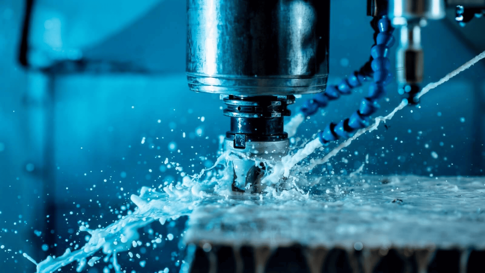
Role of Coolant and High-Pressure Lubrication
Coolant application is one of the most effective ways to influence chip formation indirectly. It reduces friction, carries away heat, and prevents chip welding. For difficult-to-cut alloys, high-pressure coolant systems (HPC) are often used. These deliver a focused jet of fluid directly at the tool–chip interface, breaking chips mechanically while cooling the edge.
Advantages of high-pressure lubrication include:
- Faster chip evacuation due to hydraulic force.
- Lower cutting temperature, reducing work hardening.
- Cleaner surface finish and longer tool life.
- Improved chip fragmentation, even at lower feed rates.
Selecting the correct coolant type is equally important. Water-based fluids with extreme-pressure additives perform well in titanium and stainless steels, while oil-based coolants are preferred for finishing Inconel to minimize built-up edge.
Best Practices and Industrial Examples
Effective chip control is achieved through a combination of sound engineering judgment, optimized process settings, and consistent observation of chip behavior. Every successful machining setup results from understanding the material’s response to cutting forces and thermal effects, then adjusting geometry, parameters, and cooling methods accordingly. The most reliable practices emerge from years of industrial experience, where safety, productivity, and part integrity are equally prioritized.

Strategies for Managing Chip Control
Before implementing any advanced strategies, machinists must focus on the fundamentals: keeping the tool sharp, maintaining clean coolant flow, and ensuring the chip evacuation path remains unobstructed. Once these basics are established, refinements in tool design and process monitoring can bring measurable improvements in efficiency and surface finish.
Summary of Effective Chip Control Strategies
Across industries, several key principles consistently prove effective in maintaining predictable chip formation and safe machining conditions:
- Match chip breaker geometry with feed rate: Use aggressive chip breakers for heavy roughing and milder designs for finishing operations to maintain optimal chip size.
- Adjust cutting speed for material behavior: Increase speed slightly to induce chip segmentation in ductile materials, but avoid overheating by monitoring chip color and tool wear.
- Maintain coolant flow directly at the tool–chip interface: Proper coolant pressure prevents chip welding and assists chip breakage.
- Use stable toolholders and minimal overhang: Reduces vibration and helps maintain consistent chip curling.
- Inspect chips frequently during setup runs: Chip shape reveals whether the cutting conditions are in control or require correction.
By combining these practices with real-time data monitoring, manufacturers can maintain a safe and efficient process even with the most demanding materials.
Aerospace Applications
In the aerospace industry, titanium and nickel-based alloys dominate due to their superior strength-to-weight ratio and temperature resistance. However, these same materials are challenging to machine without advanced chip control.
For titanium components such as landing gear shafts and turbine brackets, companies often use sharp, high-positive-rake tools with wide chip breakers and high-pressure coolant systems. This setup promotes shorter chips while maintaining dimensional accuracy. Multi-directional turning is also used to control chip flow away from the workpiece surface.
In Inconel machining, the strategy shifts toward neutral rake angles and robust step-type chip breakers. Lower speeds and heavy feeds promote segmented chips that are easier to handle. High-pressure coolant or cryogenic cooling is employed to reduce work hardening. These methods improve both surface finish and tool life while ensuring chips are consistently broken into short, controllable segments.
Medical and Energy Sector Applications
The medical sector often involves precision turning of stainless steel and cobalt-chromium alloys for implants and surgical instruments. Since these materials require fine surface finishes, chip control focuses on smooth evacuation and minimal tool pressure. Tools with small nose radii, fine chip breakers, and flood coolant systems are commonly used.
In the energy sector, components such as turbine rotors and valves are often machined from superalloys and duplex stainless steels. These operations prioritize safety and long tool life. Advanced monitoring systems are used to detect chip entanglement, allowing operators to intervene before costly stoppages occur.
Real-World Examples of Optimized Setups
Several documented industrial improvements illustrate the impact of chip control strategies:
- Aerospace supplier: By switching from a standard insert to a step-type chip breaker and increasing the feed rate by 20 percent, chip evacuation improved by 40 percent while tool life doubled.
- Medical device manufacturer: Optimizing coolant direction and using wavy chip breakers reduced burr formation on stainless steel implants, cutting polishing time by half.
- Energy component producer: Integrating vibration monitoring with adaptive feed control eliminated chip wrapping incidents in Inconel turning, improving machine uptime by 15 percent.
These results show that combining geometry design, process optimization, and real-time monitoring yields substantial benefits. Successful chip control not only enhances tool performance but also strengthens process reliability and workplace safety.
By following these best practices and learning from industrial examples, manufacturers can develop stable turning operations that handle even the toughest materials efficiently and safely.
Conclusion
Effective chip control in CNC turning is essential for maintaining safety, surface integrity, and tool longevity, especially when working with difficult materials such as titanium, Inconel, and stainless steels. Achieving this requires a deep understanding of chip formation mechanics, tool geometry, and the influence of process parameters. Well-designed chip breakers, correct rake and clearance angles, and optimized cutting conditions all work together to promote consistent chip segmentation and stable cutting forces. Proper coolant application and adaptive control systems further enhance chip evacuation, reducing heat buildup and preventing tool failure.
Modern manufacturing environments demand reliability and efficiency, and chip management plays a critical role in achieving both. Integrating optimized tooling, controlled parameters, and real-time monitoring transforms chip control from a reactive task into a proactive process. The future of machining lies in intelligent systems capable of analyzing chip behavior and adjusting conditions automatically. By combining experience-driven best practices with emerging technologies, industries can ensure smoother operations, longer tool life, and safer, higher-quality production even when machining the most challenging materials.