Introduction
The way engineers collaborate with manufacturers has changed thanks to digital 3D data. Engineers can now create a part using CAD software, submit the digital file to a manufacturer, and have the manufacturer create the part using digital manufacturing methods like CNC machining, all from the file.
The generation of comprehensive, annotated technical drawings, which is the skill of drafting, hasn't entirely been supplanted by digital files, despite the fact that they have sped up and simplified manufacture. These 2D drawings may appear antiquated in comparison to CAD, but they are nevertheless an essential tool for communicating part design information, particularly information that a CAD file cannot effectively convey.
What is 2D drawing?
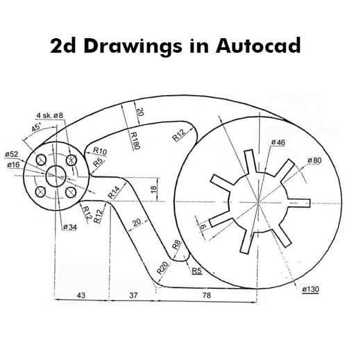
A 2D drawing, often known as an engineering drawing, is a sort of technical drawing used in the engineering field to communicate details about a part, such as its geometry, dimensions, and allowable tolerance.
An engineering drawing depicts a part in two dimensions as opposed to a digital CAD file, which depicts the part in three dimensions. But a 2D technical drawing's two-dimensional views are only one component. In addition to the part geometry, a drawing will also include qualitative information like the part's designated materials and surface treatments as well as quantitative information like dimensions and tolerances.
A sequence of 2D drawings that each depict the component from a different perspective or angle are often submitted by an engineer or drafter. (Some 2D graphics represent in-depth views of specific aspects.) Usually, an assembly drawing is used to show how different drawings relate to one another.
2D drawings have traditionally been created manually using drafting supplies, such as a drafting table, pencil, and drafting tools for creating precise circles and curves. But CAD software is now able to create 2D drawings as well. Autodesk AutoCAD, a piece of 2D drawing software that simulates the manual drafting process, is a well-known application. Additionally, using popular CAD tools like Solidworks or Autodesk Inventor, it is feasible to automatically produce 2D drawings from 3D models.
2D drawings and 3D models
It would appear that 2D drawings are no longer required because digital 3D models must inevitably describe the shape and dimensions of a part. In a certain sense, that is accurate: without anyone ever taking up a pencil, an engineer can use CAD software to design a part, and that same digital file can be delivered to a piece of machinery for fabrication.
That's not the whole picture, though, and many manufacturers value getting 2D drawings in addition to CAD files when producing parts for a client. 2D drawings adhere to common norms. They may clearly stress important dimensions and tolerances, are simple to see, can be handled in a range of conditions (unlike a computer screen), and are easy to handle. In short, manufacturers still use 2D technical drawings as their primary communication tool.
Of course, digital 3D models can handle a lot of the labor-intensive tasks, necessitating fewer 2D drawings than in the past. However, this is advantageous since it enables engineers to use 2D drawings primarily for communicating the most crucial or unusual pieces of information, such as specifications that would not be readily apparent from the CAD file.
In conclusion, 2D drawings should be used in addition to CAD files. By establishing both, you are providing manufacturers with the clearest image possible of your specifications and lowering the likelihood of misunderstandings.
It is strongly advised to all the business owners to use both 2D and 3D, on every project. In order to create an accurate quotation, this provides the clearest view of the entire portion. More information from your end will enable a manufacturer to produce your prototype or low-volume production part more quickly and effectively.
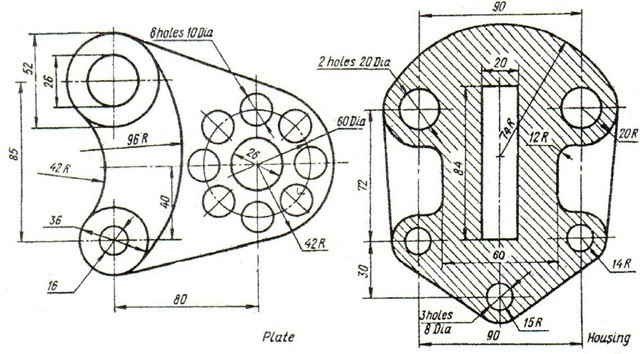
Reasons for using 2D drawings
It can appear like CAD can do everything with the inclusion of features like Model Based Definition. You can set tolerances and apply GD&T to your model in addition to designing your pieces and assembling them in three dimensions. With CAM, creating the G-code to execute your CNC machining programme is simple and doesn't require any drawing. It would seem that you could transmit this straight to the manufacturer and do away with printed designs altogether.
Wrong. Here are the top 5 reasons why 2D drawings are still necessary.
1) It is not common practice to use model-based definitions.
There's no denying that model-based definition is a neat idea and that it's growing more and more popular. To be effective, this technology must be used at both ends of the process, though. The engineer developing the part and specifying the model's tolerances is at one end of this situation. The manufacturer, who receives the design and creates the part, is on the other end. However, the manufacturer needs the appropriate tools to access the model and its annotations in order to benefit from this model-based design.
The approach also needs to take into account referring to the annotations on a 3D model rather than a 2D drawing, and this is a problem. Even with the proper software, a computer must always be available and prepared to display the CAD. Engineering drawings may not be your favorite thing to make, but manufacturers still need them!
2) 2D printed drawings are easily portable and simple to share.
Operators and shop managers don't wander the shop peering at CAD models on their laptops. They mark printed sheets of paper with critical tolerances, assembly or inspection procedures, measurement and inspection points, and critical tolerances. These sheets of paper are portable, can be hung on a wall or a bulletin board, and can be quickly marked up.
Instead of opening the model on a computer, it is frequently quicker to examine a printed drawing that is in your possession. If model-based definition isn't in place, you'll have to measure each measurement on the CAD model, which is a time-consuming workaround. You won't always have access to a computer on the production floor to view the CAD. Still, there isn't a viable way to print out a 3D model that includes all of the comments and annotations; perhaps this will be the next great thing in 3D printing.
3) A 2D illustration makes taking notes much simpler.
I think it's the most natural approach to record an idea since I enjoy the sensation of putting a pen or pencil to paper. Consider that you are having a conversation while observing the production line. While discussing ideas with another engineer, a thought suddenly enters your head. Will you locate a computer and CAD your concept? Or, while the concept is still fresh in your mind, would you prefer to sketch it out on a 2D drawing you already have? A 2D sketch is an excellent technique to share fresh concepts and make notes when you're feeling creative.
4) 2D drawings provide you a clear picture of the information you need.
Effective drawings explain what is appropriate and why that matters. You don't have to include every single dimension on a design because every geometry is recorded in the CAD model. You can create a thorough, clear, and engineering drawing by only including the essential dimensions. The spectator is aware that each and every point you made is important and deserving of their focus.
The tolerances that must be reached on crucial dimensions are easily referenced in 2D engineering drawings. Additionally, they convey the process by which separate components combine to form assemblies and offer crucial inspection points. Your drawings serve as a crucial source of information for quality assurance.
The easiest way to express some parts of your design is still through 2D drawings. For instance, the tap size and depth should always be noted along with any tapped holes. Another significant point to make is the conclusion of the information. Critical dimensions and tolerances should also be included, especially those that interface with other parts of an assembly.
5) Saving time
Saving time because fewer calculations have to be performed manually using the 2D CAD software. It enables the designer to concentrate on the areas that need more care. Digital drawings can also be quickly sent across the involved teams. It keeps everyone on the same page and allows for prompt correction of any errors or modifications discovered by any team member.
As a result, the process of developing material designs, manufacturing, fabrication detailing, or any other units, accelerates.
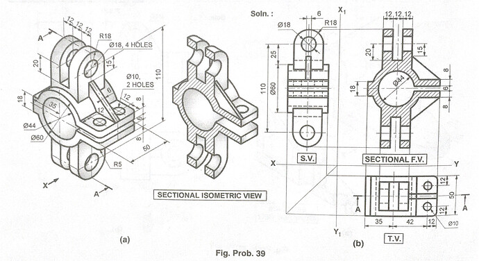
6) Sometimes words are more effective than models
Words are sometimes simply required since they are the only way to fully convey a tale. Two-dimensional (2D) drawings that include dimensions, GD&T, a title block, and annotations describe the part or assembly. On that page, you can get all the information you require. Even graphic novels require words to advance the plot; dialogue, labels, and sounds are important. 2D drawings have evolved to hold all the data required to create a part, assisting you in bringing the tale from a concept to a finished product.
Despite all of these excellent arguments for maintaining 2D engineering drawings, CAD is now an essential step in the design process. It can be tedious to make 2D designs, thus I suppose the most of us engineers are relieved about that. However, since they are so essential, 2D drawings are here to stay and don't require much time to produce. Only include the information that is absolutely necessary to make the procedure more effective! You'll save time, and your manufacturer will appreciate it.
How 2D drawings aid in the production of better parts?
When compared to using only 2D drawings, 3D CAD technology speeds up the product design process by as much as 50%. What does this mean for 2D CAD designs, though?
You might be surprised to learn that, despite the fact that 3D CAD models have transformed product design, 2D drawings are still crucial to the manufacturing process. Engineers that only use 3D models can be missing important details that could have an impact on the production process. Lack of 2D drawings may occasionally result in substantial production delays.
· Here are some reasons why 2D drawings remain useful in the production process.
- From a manufacturing standpoint, designers value concise design instructions. The nominal dimensions supplied in 3D models and the way that parts fit together once they have been built can differ. Manufacturers can benefit greatly from 2D drawings that provide detailed information on the part design for machining intent.
- Fit and usability. Dimensional specifications guarantee proper fit and operation of your parts. We lose important time and might have longer turnaround if we have to create our own set of measurements from a 3D model. However, a decent 2D drawing with complete and correct dimensional parameters enables our staff to do your job swiftly.
- Pricing. While 3D files are very helpful for producing quotations quickly, there are additional elements that could determine how much your part will cost in the end. 2D drawings make it easier to pinpoint crucial parameters or prospective problems that could have an impact on price.
Why is 2D drawing still important for the production of CNC machines?
The way engineers collaborate with manufacturers now uses 3D files. A part can now be designed by an engineer using CAD software, sent as a digital file to a manufacturer, and then manufactured by the manufacturer using digital manufacturing methods like CNC machining.
Although the development of comprehensive, annotated engineering drawings has been made easier and faster thanks to digital files, drafting still needs to be done by hand. Many people believe that creating 2D drawings is a time-consuming, pointless step in the production of custom manufactured components. A 2D part drawing is likely the most crucial phase in designing an assembly, although many engineers are unaware of this. In a 3D setting, it might be challenging, chaotic, or even impossible to express ideas that can be expressed in 2D drawings.
It seems that 2D drawings are no longer necessary because the digital 3D model must convey the part's size and shape. This is somewhat accurate: Engineers may create parts using CAD software, and the same digital file can be transferred to a machine for production without requiring anyone to pick up a pencil.
But that's not the full story; when producing parts for their clients, many manufacturers prefer to accept 2D drawings and CAD files. 2D drawings adhere to common guidelines. They clearly highlight important dimensions and tolerances, are simple to read, and can be handled in a variety of situations (unlike a computer screen). Simply said, manufacturers continue to communicate through 2D technical drawings.

· Minimize Design Errors
Design engineers can benefit much from drawings. They compel engineers to examine their components from various perspectives, which might help find design flaws that would otherwise go undetected in a 3D environment. Drawings also provide the team's other engineers with a clear, compact record of design revisions.
· Portability
Technical drawings printed in two dimensions are portable, shareable, and easy to read in a variety of settings. Manufacturers can benefit from viewing 3D models on a computer screen, but it's unlikely that every machining centre or post-processing station has a display next to it.
· Familiarity
Although CAD is common to many manufacturers, there are distinctions between the various digital forms. All professionals in the business are familiar with the standards and symbols used on 2D drawings because drafting is a well-established process. Additionally, some manufacturers can assess 2D drawings faster than a computer model (for instance, to determine the cost of a bid).
· Critical Tolerance
If the part has a 1 1/2" hole. Is there a thru hole for a 1 2" bolt there? Or a 12" bearing close-tolerance hole? Any of these that are incorrectly believed will result in your part being scrapped, expensive rework, project delays, or extra costs. This risk can be easily eliminated with accurate 2D drawings.
The machinist must make sure that every dimension or feature is machined to that tolerance if a somewhat tight standard tolerance (for example, 0.010mm) is set on a product with a 3D file, which can get quite expensive.
If you produce 2D drawings with tight and loose tolerances for increasingly crucial and less significant characteristics, respectively, you can lower the cost of a product.
· Fairly faster lead times
Compared to using CAD software, this is a much faster for opening files, measuring important measurements, and quoting. Faster quotations result in quicker manufacturing lead times, which enables us to get your parts to you more rapidly.
- Good for Quality Control
2D drawings are crucial reference materials for quality control because they offer a clear explanation of the limits that vital dimensions must achieve, the assembly process, and key parts checkpoints.
Summary
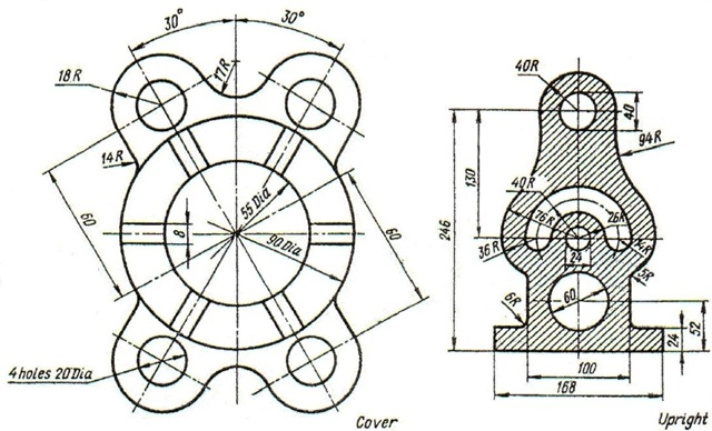
Despite the growing use of 3D CAD models, it is clear that engineering CAD designs require 2D drawings. A survey found that approximately 50% of design engineers still utilize 2D drafting when using CAD software.
Users that supply 2D drawings and 3D component files benefit from fewer design errors, quicker delivery, and higher part satisfaction. The time saved by the 2D drawings above outweighs the time and money lost on rework and project delays as a result of anticipated miscommunication by a considerable margin.


