
5 Axis CNC Machining Design: Practical design techniques to shorten lead times and reduce costs
A component may look straightforward in a CAD model but become expensive to manufacture because of restricted tool access, deep cavities, difficult workholding, or unnecessarily tight tolerances. These features can increase programming effort, machining time, inspection requirements, and production delays before the first finished part is delivered.
Effective 5 Axis CNC Machining Design addresses these problems before production begins. Although five-axis machines provide greater flexibility in cutting-tool orientation, additional axes do not automatically make every component easier or cheaper to manufacture. The best results come from designing around tool accessibility, stable fixturing, practical geometry, and the functional requirements of the finished part.
How Part Design Drives Five-Axis Machining Cost and Lead Time
The cost of a five-axis CNC component depends partly on how efficiently its geometry can be translated into machining operations. Features that appear minor in CAD can require specialized tools, additional setups, or complex toolpaths on the shop floor.
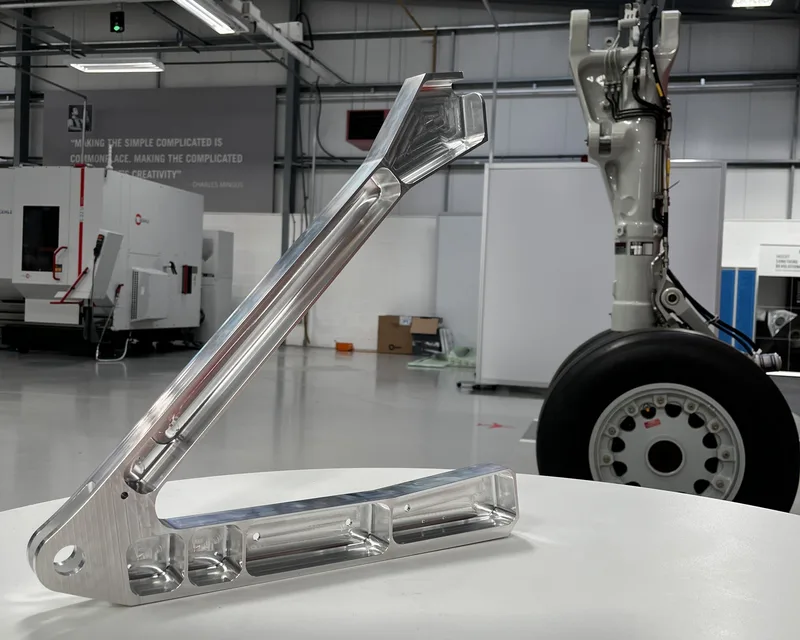
Consider a housing with angled mounting holes, deep pockets, and internal corners. The angled holes may be accessible through indexed machining, while the pockets could require long-reach cutters. If the internal corners are unnecessarily tight, smaller tools and additional finishing passes may be needed.
Each design decision affects the manufacturing route.
Design for Manufacturability (DFM) evaluates these constraints before machining begins. For five-axis components, the most useful CNC machining design guidelines focus on whether features can be reached, held securely, cut efficiently, and inspected reliably.
The objective is not to eliminate complexity wherever possible. Some geometries are necessary for assembly, performance, or weight reduction. DFM identifies features whose manufacturing difficulty can be reduced without changing their intended function.
Design for Tool Access, Cutter Stability, and Practical Geometry
Efficient five-axis machining begins with geometry that cutting tools can reach safely and machine under stable conditions. Greater freedom of tool orientation can solve some accessibility problems, but cutter dimensions, holders, fixtures, and machine travel still impose physical limits.
Provide Clearance for the Tool and Holder
A surface being visible in CAD does not mean a cutting tool can reach it.
The complete tool assembly must fit around the component, including the cutter, tool holder, and nearby machine structures. Tall bosses, narrow openings, and overhanging walls may obstruct the holder even when the cutter tip appears to have access.
Five-axis machining allows programmers to change the tool approach angle. In suitable applications, this can improve access while permitting a shorter, more rigid cutter.
Design engineers should therefore consider:
- Whether each critical feature has a practical tool approach direction.
- Whether adjacent geometry restricts cutter or holder movement.
- Whether the fixture interferes with tool access.
- Whether the required rotary movement fits within the machine's capabilities.
Collision-aware CAM software helps verify these relationships before cutting. Autodesk's multi-axis collision-avoidance tools, for example, account for both cutter-shaft and holder clearance.
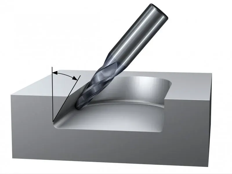
Even with this capability, enclosed features and certain undercuts may require specialized tooling, additional operations, or design changes.
Use Practical Internal Radii and Pocket Depths
Internal corner radii influence the cutting tools required for CNC milling.
A conventional end mill cannot produce a perfectly sharp internal corner in a milled pocket. Smaller specified radii generally require smaller cutters, which may be less rigid and remove material less efficiently than larger alternatives.
Where the component's function permits, increasing an internal radius can allow more practical cutter selection and reduce finishing effort.
For assemblies requiring square mating corners, a localized corner relief may provide the necessary clearance without demanding an impractical milled corner.
Pocket depth creates another design constraint.
Deep, narrow cavities can require extended tool reach, reduced cutting engagement, and careful chip evacuation. Greater tool overhang can increase deflection and vibration, potentially affecting dimensional accuracy and surface condition.
Five-axis tool orientation may help reduce the required reach, but the outcome depends on cavity geometry and available clearance.
Sandvik Coromant's guidance on closed pockets illustrates why different pocket geometries require different multi-axis approaches and cutter strategies.
Control Thin Walls and Difficult Features
Thin walls can deform under cutting forces or clamping pressure. Their machining behavior depends on wall height, thickness, material stiffness, support, and cutting conditions.
A wall that performs adequately in aluminum may require a different machining strategy when produced from stainless steel or titanium.
Engineers should evaluate whether:
- Wall thickness is appropriate for the intended function.
- Tall or slender features have sufficient support.
- Clamping could distort critical geometry.
- Material can remain during roughing to support delicate features.
- Holes, threads, and undercuts require unnecessarily difficult access.
These considerations do not justify imposing one minimum wall thickness across every design.
The appropriate dimensions and machining sequence depend on the component, material, and manufacturing process.
Plan Workholding and Datums to Minimize Setup Transfers
CNC machining setup optimization depends on holding the component securely while preserving access to the features that must be machined.
One advantage of five-axis machining is the ability to reach multiple surfaces without repeatedly removing and reclamping the workpiece. This can reduce handling and help maintain relationships between critical features.
Consider an industrial housing containing mounting holes on several faces and an angled port connected to a precision bore.
If the component must be repositioned repeatedly, the manufacturer must reestablish its location relative to the cutting tools. Each transfer introduces additional setup work and another opportunity for positional variation.
Indexed five-axis machining may allow several features to be produced while the housing remains in its original fixture.
The fixture itself must still provide adequate support and clearance. A clamp that blocks a critical surface or interferes with rotary movement can eliminate the expected setup advantage.
Designers can improve manufacturability by providing stable locating surfaces and clearly identifying functional datums.
Datum planning is particularly important when holes, bores, and mating faces must maintain precise geometric relationships.
Not every component can be completed in one setup. Underside features, inaccessible regions, and the removal of temporary holding material may still require additional operations.
The goal is to minimize unnecessary transfers while maintaining safe cutting conditions and reliable dimensional control.
Select 3-Axis, Indexed 3+2, or Simultaneous 5-Axis Machining
The appropriate machining strategy depends on the part's geometry and the tool orientations required to produce it.
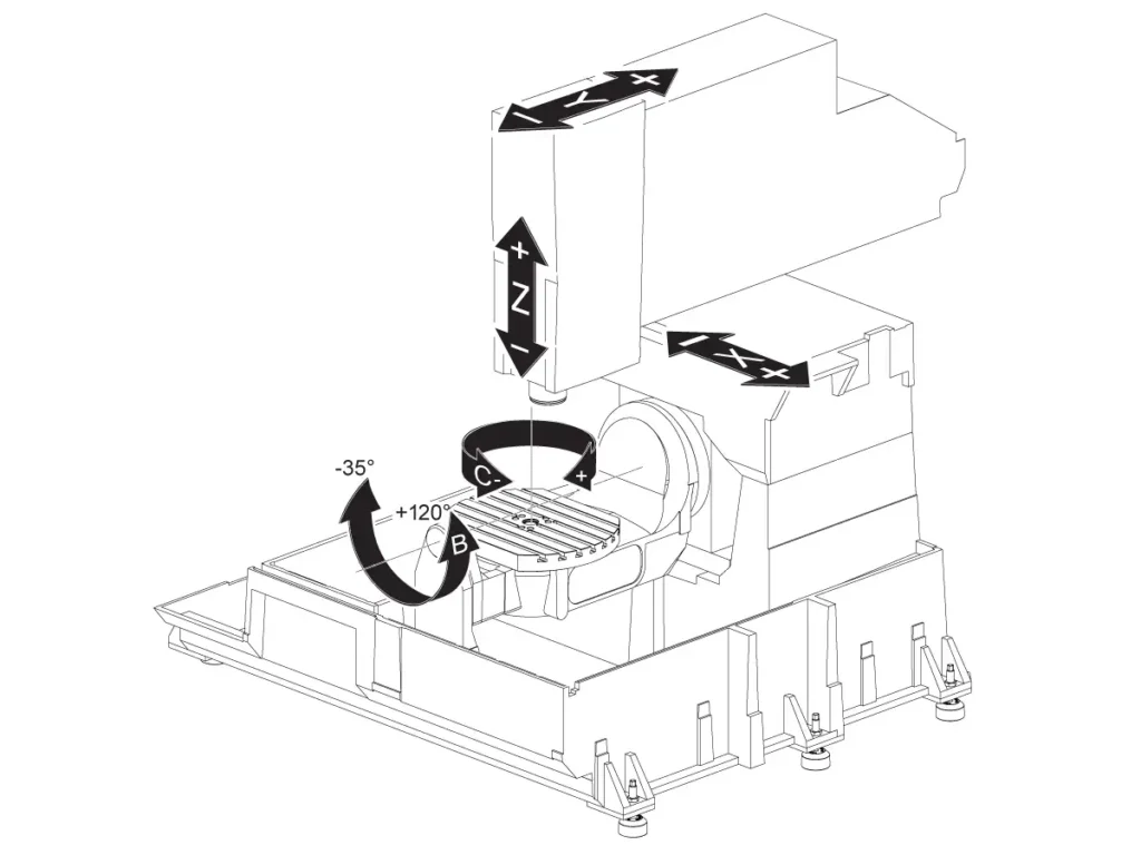
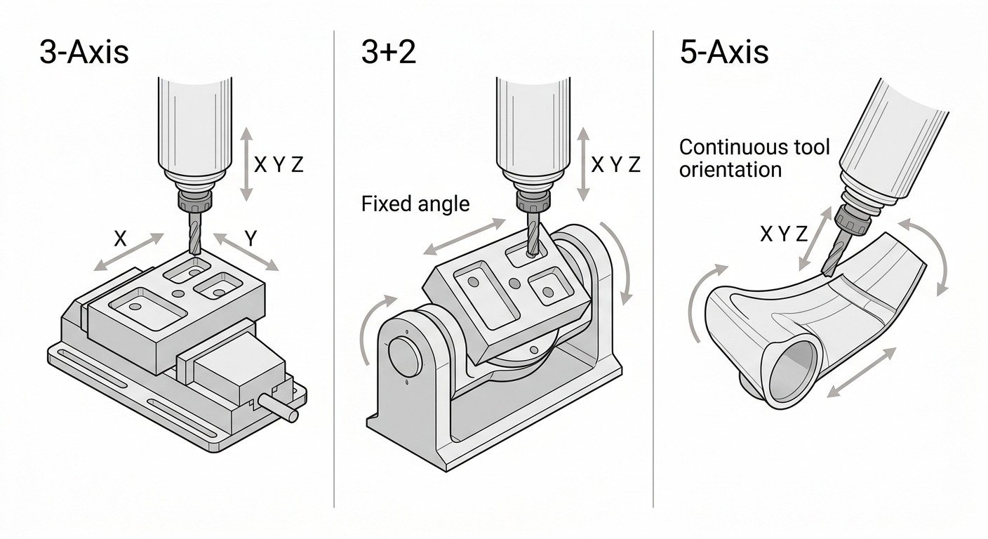
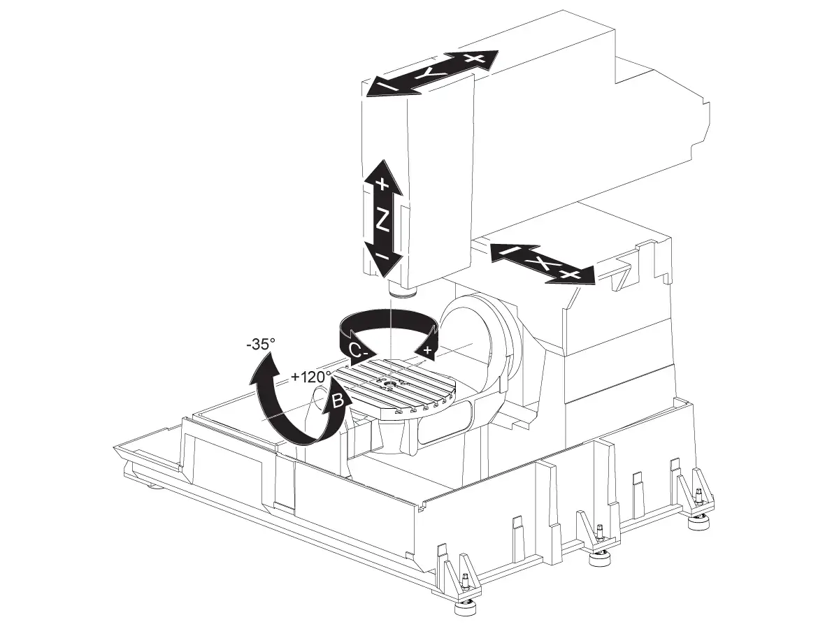
A five-axis machine typically provides three linear axes and two rotary axes, although the arrangement varies by machine configuration. Not every operation requires all axes to move simultaneously.
Indexed 3+2 Machining for Fixed-Angle Features
Indexed 3+2 machining positions the workpiece or tool at a selected angle before cutting with the linear axes.
It is often suitable for angled holes, inclined surfaces, and features located on multiple sides of a component.
This approach can reduce manual repositioning while avoiding continuous rotary-axis movement during cutting.
Simultaneous Five-Axis Machining for Complex Contours
Simultaneous five-axis machining coordinates linear and rotary movements during cutting.
This is useful when the tool must continuously change its orientation to follow complex surfaces.
Impellers and similarly contoured components are established applications. Their changing surface geometry may make fixed-angle cutting less practical.
The additional flexibility also requires careful control of toolpaths, machine kinematics, and collision clearance.
| Decision Factor | 3-Axis Machining | Indexed 3+2 Machining | Simultaneous 5-Axis Machining |
|---|---|---|---|
| Geometry | Accessible prismatic features | Multi-face and angled features | Complex changing contours |
| Tool orientation | Fixed during cutting | Multiple indexed angles | Continuously adjustable |
| Setup requirements | Additional fixtures may be needed | Can reduce reclamping | Can reduce reclamping |
| Programming | Generally simpler for basic parts | Requires indexed planning | More complex tool-axis control |
| Cost considerations | Efficient for simple geometry | May reduce multi-face setup effort | Can justify complexity for demanding geometry |
| Main limitation | Restricted approach directions | Fixed orientation during each cutting operation | Greater programming and verification demands |
A component may use conventional, indexed, and simultaneous toolpaths within the same manufacturing plan. The best approach is the one that satisfies the geometry efficiently and reliably.
Match Material, Tolerance, Surface Finish, and Inspection to Function
Material selection and quality specifications directly influence machining difficulty. Engineers should distinguish the ability to create a component's geometry from the ability to deliver its final functional dimensions and surface condition.
Account for Material-Dependent Machining Behavior
Aluminum alloys often support efficient milling, but thin features can still experience deflection or distortion.
Stainless steels require attention to grade-dependent machinability, cutting heat, and possible work hardening.
Titanium alloys introduce heat-management and tool-wear challenges because of their relatively poor thermal conductivity. Stable cutting strategies are particularly important when machining expensive stock.
Engineering plastics present different concerns, including thermal expansion and sensitivity to clamping forces.
Material selection should reflect the component's performance requirements, with machining behavior considered during design.
Separate Shape Creation, Functional Finishing, and Verification
Creating the basic geometry does not necessarily complete every functional requirement.
Precision bores, bearing seats, sealing surfaces, threads, and mating faces may need dedicated finishing operations or additional inspection.
Engineers should identify which features require tight dimensional control rather than applying restrictive tolerances across the entire component.
A close-fitting bore may require careful finishing and measurement, while an external clearance surface may not need the same level of control.
Surface roughness and dimensional tolerance are also separate specifications. A component can meet its dimensional requirements while having an unsuitable surface condition for its intended function.
Inspection provides the final confirmation.
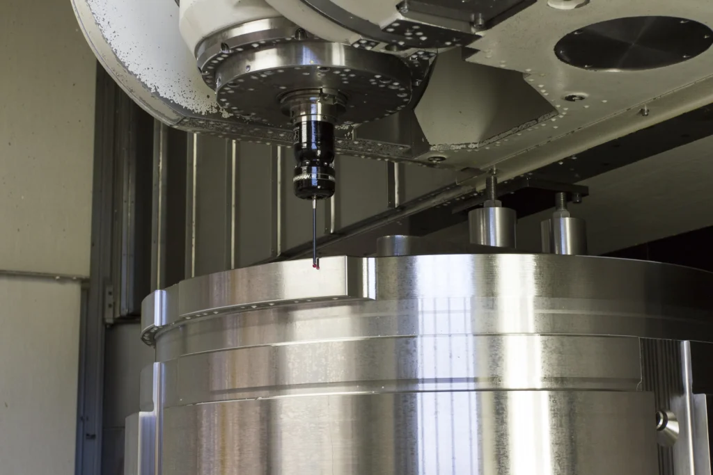
Coordinate Measuring Machines (CMMs) can verify dimensional and geometric characteristics when suitable measurement methods are used. In-process probing can support setup checks and machining control, but it does not automatically replace final acceptance inspection.
Rotary-axis alignment and positioning errors can also influence the machining result, even when a component remains in one fixture. Machine calibration and measurement planning must therefore reflect the required part accuracy.
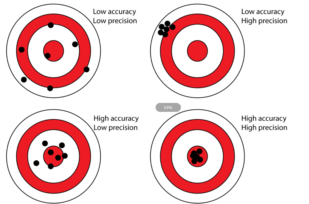
Machine accuracy and finished-part acceptance should not be confused. ISO 10791-6 addresses machine kinematic testing, while ISO 10791-7 addresses accuracy testing with finished test pieces. Neither establishes a universal production tolerance for every component.
Final verification must reflect the drawing requirements, measurement capability, and condition of the finished part.
Evaluate Cost and Lead Time Across the Complete Manufacturing Route
Design changes reduce CNC machining costs when they eliminate unnecessary work across the manufacturing process.
A five-axis machine may have a higher operating cost per hour than simpler equipment. For suitable components, savings from reduced setup transfers, improved access, or fewer secondary operations may offset that expense.
The relevant comparison is total manufacturing cost per accepted component, not machine hourly rate alone.
Important cost drivers include:
- Raw material: Grade, stock dimensions, availability, and material removal.
- Programming: CAM preparation, toolpath development, and verification.
- Workholding: Fixture design, setup preparation, and repeated positioning.
- Machining: Cutting time, tool selection, tool wear, and material-removal requirements.
- Quality control: Inspection, measurement planning, and possible corrective work.
- Finishing: Surface treatment and other required secondary operations.
Production quantity also matters. Programming and fixture preparation may represent a substantial portion of a prototype's cost, while machining time and tool wear become increasingly important during repeated production. Reusing a validated program and fixture may also distribute initial preparation costs across a larger quantity.
Reducing Lead Time Without Compromising Production
CNC machining lead time reduction requires more than faster cutting.
The full delivery schedule includes engineering review, material procurement, programming, fixture preparation, machining, inspection, finishing, and production scheduling.
A design with accessible geometry and clear specifications can reduce manufacturing uncertainty.
For example, simplifying a difficult pocket may shorten programming and machining work. Yet the overall delivery date may remain unchanged if material procurement or outside finishing is the main bottleneck.
Engineers should therefore review manufacturability and production readiness together.
The most valuable improvements are those that remove avoidable operations without introducing new quality risks.
Check Manufacturability Before Sending the Design for Quotation
A practical DFM review helps engineers identify production challenges before finalizing a five-axis CNC design.
Before submitting a component for quotation, confirm the following:
- Critical features are accessible to appropriate cutting tools.
- Internal radii, pockets, and wall geometry are functionally justified.
- Suitable locating and clamping surfaces are available.
- Important datum relationships are clearly defined.
- Material specifications match the intended application.
- Tight tolerances are limited to features that require them.
- Surface-finishing and inspection requirements are identified.
- CAD models and technical drawings communicate the necessary information.
- Production quantities and delivery expectations are provided.
Manufacturing engineers can then evaluate whether geometry changes, alternative toolpaths, or different workholding approaches would improve production.
This review is especially useful before tooling, programming, and material procurement commitments are made.
Frequently Asked Questions
Is five-axis CNC machining cost-effective for a single prototype?
It can be when complex geometry would otherwise require extensive repositioning, specialized fixtures, or multiple machining operations. For simple components, three-axis machining may be more economical. The decision depends on programming, setup, machining, and inspection costs.
What CAD files and drawing details should engineers provide for an accurate five-axis machining quote?
Provide a suitable 3D CAD model, technical drawings, material specifications, critical tolerances, surface-finish requirements, and expected quantities. Identify functional datums and important assembly relationships. These details help the manufacturer evaluate tooling, setups, and inspection requirements.
Should critical tolerances be verified before or after surface finishing?
Verification should reflect the component's manufacturing sequence and final acceptance requirements. In-process inspection can identify problems before finishing, while final inspection may be necessary when coatings or other surface treatments affect critical dimensions. The drawing should clarify whether dimensions apply before or after finishing.
Conclusion
Effective five-axis CNC design starts with understanding how component geometry affects the actual machining process.
Practical tool access, suitable internal radii, stable workholding, and function-based tolerances can reduce avoidable manufacturing complexity. Indexed 3+2 and simultaneous five-axis machining should be selected according to geometry rather than machine capability alone.
Before production, engineers should evaluate the complete manufacturing route, including machining, finishing, and inspection.
BaiChuan Precision Manufacturing provides custom CNC milling services and can review component drawings, material requirements, and production specifications to discuss manufacturability and prepare a project-specific quotation.
References
1. Protolabs. Designing for Machinability.
2. Sandvik Coromant. Milling Closed Pockets or Angles.
3. Sandvik Coromant. Solid Round Tools - Session 11.
4. Autodesk. Avoid Collisions in a Toolpath.
_5. Haas Automation. 5-Axis Machining for Everyone._
6. Gao et al. Machine Tool Calibration. 2023.
7. Renishaw. AxiSet Check-Up.
8. ISO. ISO 10791-6:2014 - Accuracy of Speeds and Interpolations.
9. ISO. ISO 10791-7:2020 - Accuracy of Finished Test Pieces.