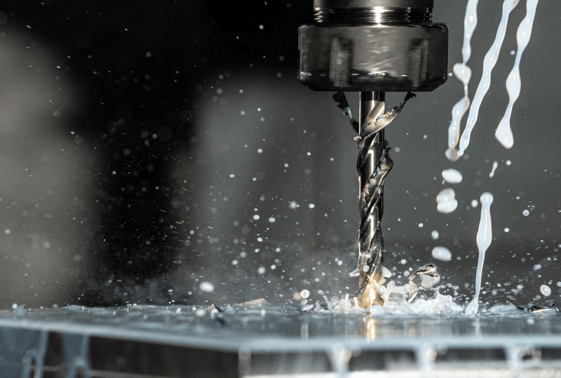
CNC milling is one of the most widely used manufacturing processes in modern engineering. It allows precise shaping of metal and other materials using computer-controlled cutting tools. Engineers rely on CNC milling to produce components for industries such as aerospace, automotive, medical devices, and industrial machinery. When planning a machining strategy, one of the most common decisions is whether a part should be produced using 3-axis or 5-axis milling.
3-Axis vs. 5-Axis CNC Machining
At first glance, both methods may appear similar because they use rotating cutting tools and programmable motion. However, the number of axes significantly affects how a part can be machined. While 3-axis machines are well-suited for many standard components, 5-axis machines offer far greater flexibility when dealing with complex geometry. Understanding the differences between these two approaches helps engineers choose the most efficient method for manufacturing a specific part.
Understanding 3-Axis CNC Milling
3-axis CNC milling is the most widely used machining method in manufacturing workshops. In this setup, the cutting tool moves along three linear directions while the workpiece remains fixed on the machine table. Because the motion is straightforward and well understood, engineers often rely on 3-axis machines for many standard mechanical components.
Although the technology is relatively simple compared with multi-axis systems, it remains highly effective for parts that do not require complex angles or curved surfaces. Many industrial components are still designed specifically so they can be produced efficiently using this traditional milling configuration.
Basic Motion and Operation
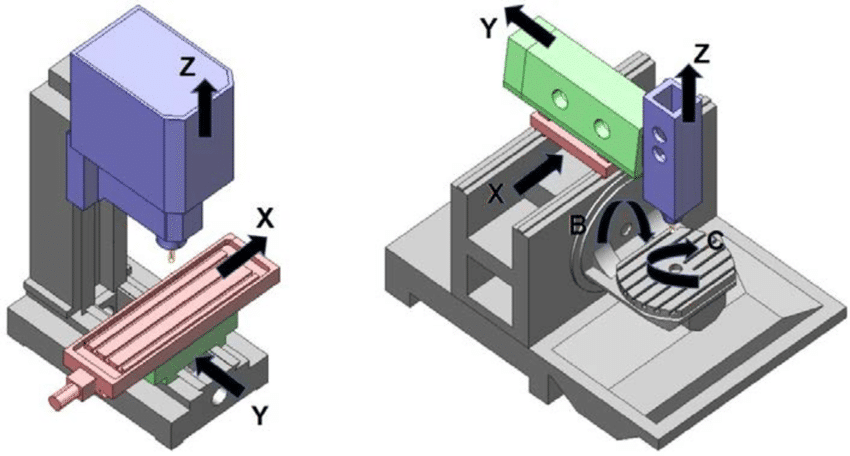
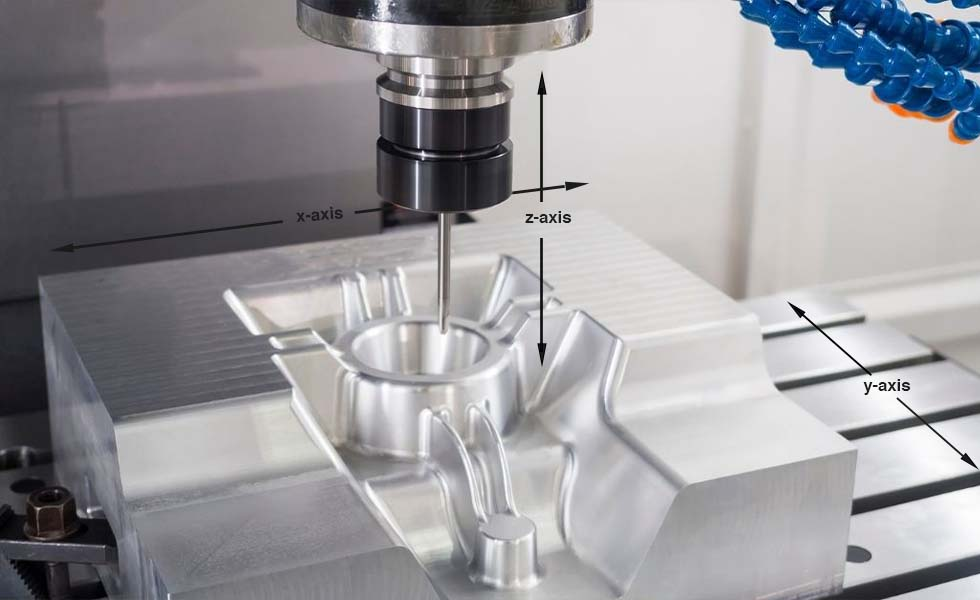
In a 3-axis milling machine, the cutting tool moves in three linear directions that correspond to the X, Y, and Z axes. Each axis controls a specific direction of motion.
- X-axis movement
This motion moves the cutting tool from left to right across the workpiece. It is commonly used when machining slots, long edges, or horizontal profiles.
- Y-axis movement
The tool moves from front to back relative to the operator. This direction allows the machine to create pockets, contours, or internal features across the surface of the material.
- Z-axis movement
This controls the vertical position of the cutting tool. The tool moves up and down to remove material at different depths.
In most cases, the cutting tool approaches the workpiece from above. The workpiece remains fixed in a vise or fixture while the tool moves along these three directions to remove material layer by layer.
For example, consider a rectangular aluminum plate used as a mounting base for an electric motor. The part may require drilled holes, a central pocket, and several threaded features. A 3-axis machine can easily produce these features by moving the tool across the surface and gradually cutting to the required depths.
Common Applications
Because of its straightforward motion, 3-axis machining is typically used for components with relatively simple geometry. Many industrial parts fall into this category, especially those used in mechanical assemblies.
You will often see 3-axis milling used for components such as:
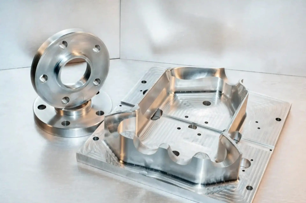
- Flat plates and brackets
Structural plates, mounting brackets, and support frames are common examples. These parts often require drilling, slotting, and basic pocketing operations.
- Mounting components
Machine bases and fixture plates often include multiple holes and shallow cavities. A 3-axis machine can handle these features efficiently.
- Machine housings
Many housings used in pumps, gearboxes, or industrial equipment have flat surfaces and drilled holes that can be machined from one direction.
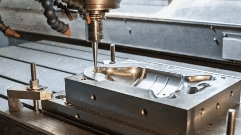
- Mold bases
In mold manufacturing, the base plates for injection molds or die casting tools are often machined using 3-axis equipment before additional features are added.
For instance, a fixture plate used on an assembly line might contain dozens of precision holes for locating pins and clamps. A 3-axis milling machine can drill and machine these features with high accuracy in a single setup.
Advantages
One reason 3-axis machining remains so common is its practicality. Many workshops rely on these machines because they provide a reliable balance between cost, capability, and productivity.
Several benefits make 3-axis milling attractive for many engineering projects:
- Lower machine cost
Compared with multi-axis machines, 3-axis mills are significantly less expensive to purchase and maintain. This makes them accessible to small and medium-sized manufacturing shops.
- Simpler programming
CAM programming for 3-axis machining is generally easier. Toolpaths are straightforward because the tool approaches the workpiece from one primary direction.
- Well-suited for standard components
Many mechanical parts are designed with flat surfaces and perpendicular features. These geometries align well with the capabilities of 3-axis machines.
- Wide availability
Because the technology has been widely adopted for decades, most manufacturing facilities already have 3-axis machines available.
In many production environments, engineers intentionally design parts so they can be manufactured using 3-axis machining. Doing so reduces production costs and simplifies the manufacturing process.
Limitations
Despite its advantages, 3-axis machining does have several limitations. These become more noticeable as the geometry becomes more complex.
Several challenges arise when working with intricate designs:
- Multiple setups may be required
When features exist on several sides of a part, the workpiece must often be repositioned between operations. Each repositioning step increases production time and introduces potential alignment errors.
- Deep cavities are difficult to machine
When cutting deep pockets or narrow cavities, the tool must extend further from the spindle. This can reduce tool stability and affect surface quality.
- Angled features are harder to produce
Features such as angled holes, curved surfaces, or complex contours may require specialized fixtures or multiple machining steps.
For example, imagine a mechanical component that contains angled channels on several faces. Producing these features with a 3-axis machine would require rotating the part several times and re-aligning it for each operation.
As part geometry becomes more demanding, these limitations often encourage engineers to explore more advanced machining approaches. One of the most powerful alternatives is 5-axis CNC milling, which significantly expands the range of possible tool movements.
Understanding 5-Axis CNC Milling
As engineering designs become more complex, traditional machining approaches often reach their limits. Components used in aerospace, medical devices, and advanced machinery frequently contain curved surfaces, angled features, and intricate internal structures. Producing these parts efficiently requires greater flexibility in how the cutting tool approaches the material. This is where 5-axis CNC milling becomes valuable.
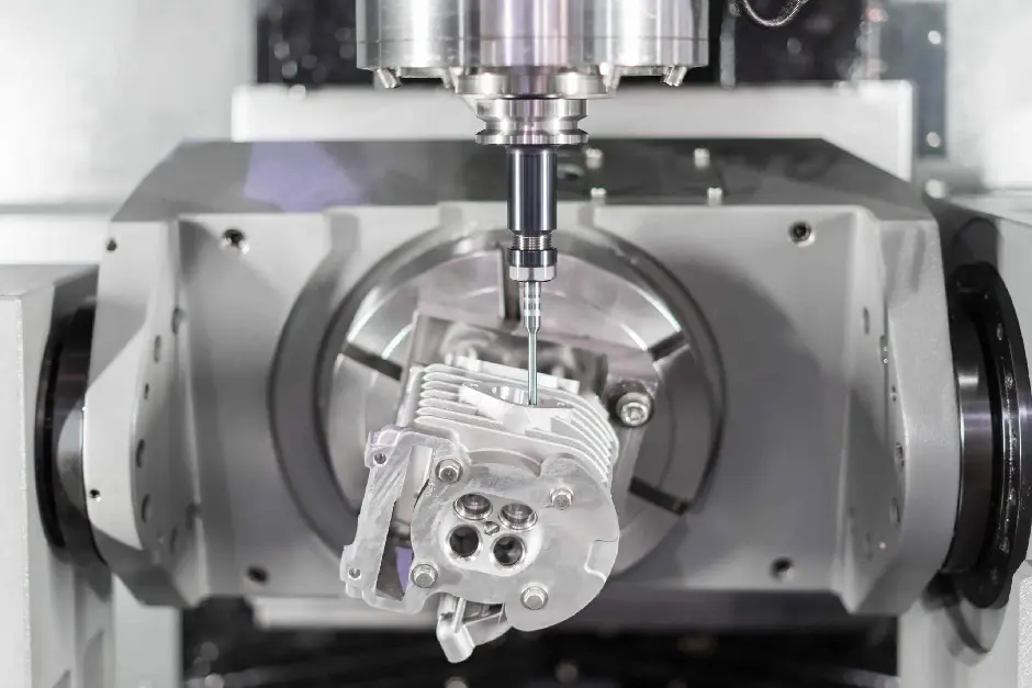
A 5-axis machine expands the capability of traditional milling by allowing the cutting tool or the workpiece to rotate during machining. Instead of approaching the part from only one direction, the tool can reach the surface from many different angles. This capability allows engineers to machine complex shapes that would otherwise require numerous setups on a 3-axis machine.
Additional Axes Explained
A 5-axis milling machine still uses the same three linear movements found in a traditional mill. The difference is the addition of two rotational axes that allow the cutting tool to tilt and rotate relative to the workpiece.
The primary motions involved are:
- X-axis movement
Controls left to right movement of the tool across the workpiece. This motion is used for cutting profiles and positioning the tool along the horizontal plane.
- Y-axis movement
Moves the tool from front to back across the material. This direction allows the machine to create pockets, channels, and internal features across the surface.
- Z-axis movement
Adjusts the vertical position of the tool. The cutting tool moves downward to remove material and upward when repositioning between toolpaths.
In addition to these three linear directions, 5-axis machines add two rotational movements.
- A-axis rotation
Rotates the workpiece or tool around the X-axis. This motion allows the cutting tool to approach the material at different tilt angles.
- B-axis rotation
Rotates around the Y-axis. Depending on the machine design, some systems use a C-axis rotation around the Z-axis instead.
These additional movements allow the tool to maintain an optimal cutting angle while moving across complex surfaces. This capability becomes particularly useful when machining sculpted shapes or curved profiles.
How 5-Axis Machining Works
In a typical 5-axis machining process, the machine continuously adjusts the orientation of the cutting tool while removing material. Instead of stopping the machine to reposition the part, the control system automatically rotates the tool or the workpiece during the operation.
This dynamic movement allows the tool to follow complex surfaces more accurately. Because the machine maintains the correct tool angle, it often produces smoother surfaces and more consistent cutting conditions.
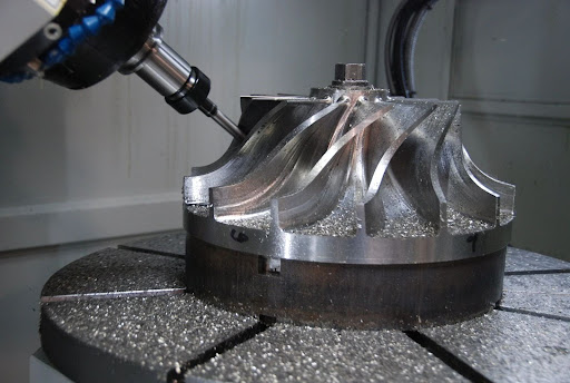
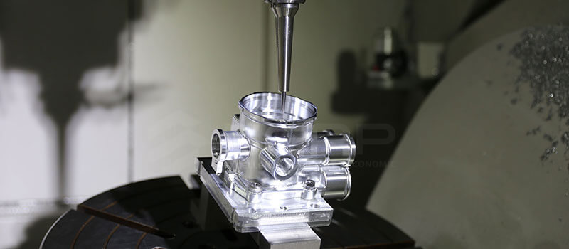
Consider the example of a turbine blade used in an aircraft engine. The blade contains twisted aerodynamic surfaces that change angle along its length. Producing this geometry on a 3-axis machine would require multiple setups and specialized fixtures. A 5-axis machine can approach the blade from different directions during a single operation, allowing the curved surfaces to be machined more accurately.
Another example can be found in orthopedic medical implants. Many implants contain organic shapes designed to match the natural contours of the human body. A 5-axis machine allows the cutting tool to follow these curves smoothly, improving both precision and surface quality.
Advantages
The ability to adjust tool orientation during machining provides several important benefits for engineers and manufacturers.
- Machining complex geometry
Curved surfaces, sculpted profiles, and multi-angle features become much easier to produce. Components such as impellers, turbine blades, and aerospace brackets often rely on 5-axis machining.
- Reduced setups
Many parts that previously required several repositioning steps can now be machined in a single setup. This reduces alignment errors and simplifies the production process.
- Improved surface finish
Because the cutting tool can remain closer to its optimal angle, the cutting action becomes smoother. This often results in better surface quality, particularly on curved surfaces.
- Shorter machining cycles
Fewer setups and more efficient toolpaths can significantly reduce total machining time for complex components.
For example, an aerospace impeller with multiple twisted blades may require five or six setups on a traditional machine. A 5-axis system can machine the entire part in one continuous operation, reducing both labor time and production complexity.
Challenges
While 5-axis machining offers powerful capabilities, it also introduces additional complexity in both equipment and operation.
- Higher machine cost
Multi-axis machines require more advanced mechanical systems and control software. As a result, their purchase price and maintenance costs are significantly higher than those of 3-axis machines.
- More complex programming
Toolpath planning for 5-axis machining requires advanced CAM software and experienced programmers. Engineers must carefully control tool orientation, collision avoidance, and machining strategy.
- Skilled operators are essential
Operating a 5-axis system requires deeper technical knowledge. Operators must understand tool dynamics, machine kinematics, and advanced machining strategies.
For many workshops, the decision to invest in 5-axis equipment depends on the type of parts they produce. When a project involves complex geometry or tight machining tolerances, the advantages of 5-axis machining often justify the additional investment.
Understanding these capabilities helps engineers evaluate how each machining method performs under real manufacturing conditions. The next step is to examine the key differences between 3-axis and 5-axis milling across several important engineering factors.
Key Differences Between 3-Axis and 5-Axis Milling
Both 3-axis and 5-axis CNC milling rely on the same fundamental machining principle. A rotating cutting tool removes material from a fixed workpiece according to programmed toolpaths. The difference lies in how the tool approaches the part and how many directions of motion are available during machining.
These differences influence several important factors in manufacturing. Engineers often compare the two methods based on machining complexity, setup requirements, and surface quality. Understanding these aspects helps determine which method is better suited for a particular component.
Machining Complexity
One of the most noticeable differences between the two technologies is the type of geometry they can handle efficiently.
3-axis machining
3-axis milling performs best when parts contain straightforward shapes and features that can be accessed from one direction. In these situations, the tool can move across the surface without needing to tilt or rotate.
You will typically see 3-axis machining used for parts such as:
- Prismatic components
These parts contain flat faces, straight edges, and right angles. Examples include fixture plates, mounting brackets, and machine bases.
- Flat surfaces with drilled holes
Many structural parts require holes, slots, or shallow pockets that can be machined directly from the top surface.
- Straight channels and pockets
Components with simple internal cavities or rectangular pockets are ideal for this machining approach.
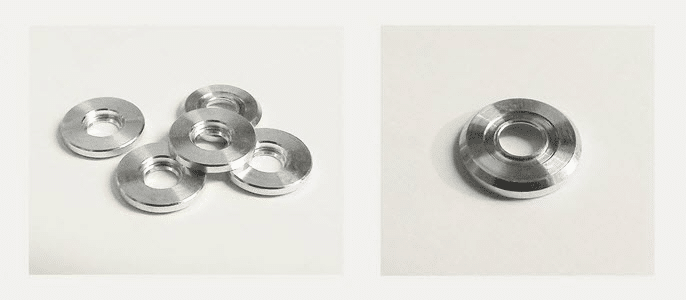
A good example is a CNC aluminum fixture plate used in assembly lines. The plate may contain dozens of drilled holes and shallow pockets, all of which can be produced efficiently with standard 3-axis toolpaths.
5-axis machining
5-axis milling becomes valuable when the geometry of a part extends beyond flat surfaces and straight features. The additional rotational axes allow the cutting tool to approach the workpiece from multiple directions.
Parts that benefit from 5-axis machining often involve:
- Curved and sculpted surfaces
Components such as turbine blades or aerodynamic panels require the cutting tool to follow complex curves.
- Multi-angle features
Some designs include angled holes, sloped faces, or surfaces that cannot be accessed from a single vertical direction.
- Organic or freeform shapes
Medical implants and high-performance automotive components frequently contain smooth, flowing geometries that demand flexible tool orientation.
An aerospace impeller offers a clear example. The blades twist and curve around the central hub, creating surfaces that require the cutting tool to approach the part from several angles during machining.
Setup Requirements
Another major difference between these machining approaches involves how the part is positioned during manufacturing.
3-axis machining setups
When features appear on multiple faces of a component, the workpiece often needs to be repositioned during the machining process. Each repositioning step involves removing the part from the fixture, rotating it, and aligning it again on the machine table.
This workflow may involve several steps:
- The part is first machined from the top surface.
- The operator flips the workpiece to access another face.
- Additional features are machined after realigning the part.
For instance, imagine a part that contains features on five different sides. Producing those features on a 3-axis machine would likely require several setups. Each setup adds extra time and introduces a small risk of alignment error.
5-axis machining setups
A 5-axis machine can access multiple faces of the workpiece without physically repositioning it. The machine simply rotates the tool or the part to reach the desired angle.
This capability improves both efficiency and accuracy.
- Several sides of a component can be machined during a single setup.
- Alignment remains consistent because the part stays fixed in one fixture.
- Production time decreases because manual repositioning is eliminated.
In aerospace manufacturing, this advantage becomes particularly important. A structural bracket with features on multiple faces can often be machined entirely in one setup using a 5-axis machine.
Surface Quality
Surface finish is another area where differences between the two technologies become noticeable.
Surface quality in 3-axis machining
When machining curved surfaces with a 3-axis machine, the cutting tool may not always remain at the most effective angle relative to the surface. This limitation can lead to less efficient cutting conditions.
In practice, engineers may observe:
- Slightly rougher surface textures on complex curves
- Higher tool wear when machining deep or angled features
- Additional finishing operations to achieve the desired surface quality
While these issues are manageable, they can increase production time for parts that contain complex surfaces.
Surface quality in 5-axis machining
A 5-axis machine can maintain a more favorable cutting angle as the tool moves along the surface. This flexibility improves cutting efficiency and often produces smoother results.
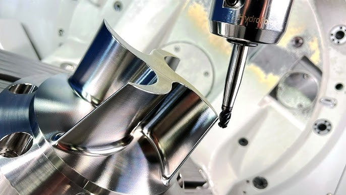
a Perfect Surface Finish | DVF 5000 5 Axis CNC Machine
Several benefits become noticeable:
- Improved surface finish
The cutting tool maintains better contact with the surface, which reduces visible tool marks.
- Longer tool life
Because the cutting angle remains more stable, cutting forces are distributed more evenly across the tool.
- Higher machining efficiency
Toolpaths can follow curved surfaces more naturally, reducing unnecessary movements.
Medical implants illustrate this advantage well. Orthopedic components such as knee or hip implants require smooth, curved surfaces to function correctly within the human body. 5-axis machining allows manufacturers to produce these surfaces with high precision and minimal finishing work.
These differences highlight how each machining method performs in real manufacturing environments. The next step is to examine situations where the simpler 3-axis approach still offers the most practical solution.
Conclusion
Both 3-axis and 5-axis CNC milling play important roles in modern manufacturing. 3-axis machining remains the most practical choice for many standard components with flat surfaces, simple pockets, and straight holes. It offers lower equipment costs, simpler programming, and reliable performance for high-volume production. For workshops producing brackets, plates, housings, and other prismatic parts, 3-axis milling continues to be an efficient and economical solution.
5-axis machining becomes valuable when part geometry becomes more complex. Curved surfaces, angled features, and multi-face components can often be produced in a single setup, improving accuracy and reducing overall machining time. Although the equipment and programming are more demanding, the capability it provides is essential for industries such as aerospace, medical devices, and advanced engineering. In practice, the right choice depends on part complexity, production volume, and budget considerations. Engineers who understand these factors can select the machining approach that delivers the best balance between cost, precision, and efficiency.