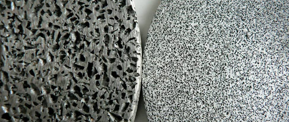
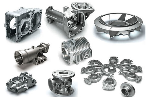
Porosity in die casting refers to the presence of small voids or cavities trapped inside or on the surface of a cast component. These voids form during the metal filling and solidification stages and are often invisible to the naked eye. While porosity is common in high-pressure die casting, its presence directly affects the structural integrity, appearance, and reliability of the final part.
Porosity is considered a critical quality issue. In demanding applications such as automotive, aerospace, and industrial equipment, even minor porosity can lead to part rejection or premature failure. This article explains what porosity is, why it occurs, the different types found in die casting, and proven methods manufacturers use to prevent it through better design and process control.
What Is Porosity in Die Casting
Porosity in die casting is one of the most common and challenging defects faced by manufacturers. It occurs when voids form inside the metal or appear on the surface of a cast part during filling and solidification. These voids may be microscopic or large enough to affect performance, depending on how and why they form.
At its core, porosity is a result of trapped gases, metal shrinkage, or interrupted metal flow. Because die casting operates at high speed and high pressure, even small process variations can introduce porosity that is difficult to predict or fully remove.
Simple definition of porosity
Porosity is the presence of unwanted empty spaces within a die-cast component. These spaces may contain gas or simply be empty cavities created as the metal solidifies. In practical terms, porosity means the metal is not fully dense in certain areas.
For example, a die-cast aluminum housing may appear solid from the outside but contain internal voids that weaken threaded holes or sealing surfaces.
How porosity forms during the die casting process
Porosity forms mainly during two stages of the process:
- Metal filling
As molten metal enters the die cavity at high velocity, air and gases can become trapped if they are not properly vented. This trapped gas later appears as gas porosity.
- Solidification and cooling
As the metal cools, it shrinks. If there is not enough molten metal feeding the shrinking areas, voids form. This leads to shrinkage-related porosity, often located in thicker sections.
In real production environments, these mechanisms often overlap, making the root cause harder to isolate.
Difference between surface porosity and internal porosity
Porosity can be classified based on where it appears in the part.
- Surface porosity
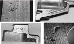
This type appears as small pits or blisters on the surface. It is usually visible after machining or surface finishing and can affect coating adhesion or cosmetic quality.
- Internal porosity
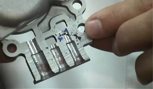
Internal porosity is hidden beneath the surface and is typically detected through X-ray or pressure testing. It is more dangerous because it can reduce strength, cause leaks, or lead to failure under load.
For instance, internal porosity in a hydraulic valve body may pass visual inspection but fail during pressure testing.
Why is porosity difficult to eliminate completely?
Porosity cannot be fully eliminated in most die casting processes due to several inherent limitations:
- High injection speeds increase the risk of air entrapment
- Complex part geometries restrict smooth metal flow
- Rapid cooling limits feeding during solidification
- Production pressures prioritize speed over perfect filling conditions
Because of these factors, the goal in die casting is not total elimination of porosity but controlling it to levels that do not affect function, safety, or service life. This is why process optimization and early design decisions play a critical role in porosity management.
Common Types of Porosity in Die Casting
Porosity in die casting does not appear in a single form. Different mechanisms during filling and solidification create different porosity patterns, each with its own impact on part quality and performance. Understanding these types helps manufacturers identify root causes more accurately and apply targeted prevention methods instead of broad process changes.
Gas porosity
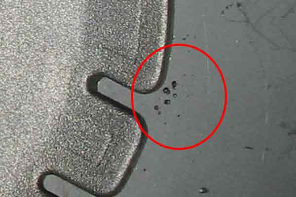
Gas porosity occurs when gases become trapped inside the molten metal during injection and remain there as the metal solidifies. These gases may come from air in the die cavity, moisture on the die surface, lubricants, or dissolved gases in the melt itself.
Gas porosity often appears as small, round voids and is commonly found near the surface of the part. In aluminum die casting, for example, gas porosity can cause blistering after heat exposure or painting, leading to cosmetic defects and coating failures.
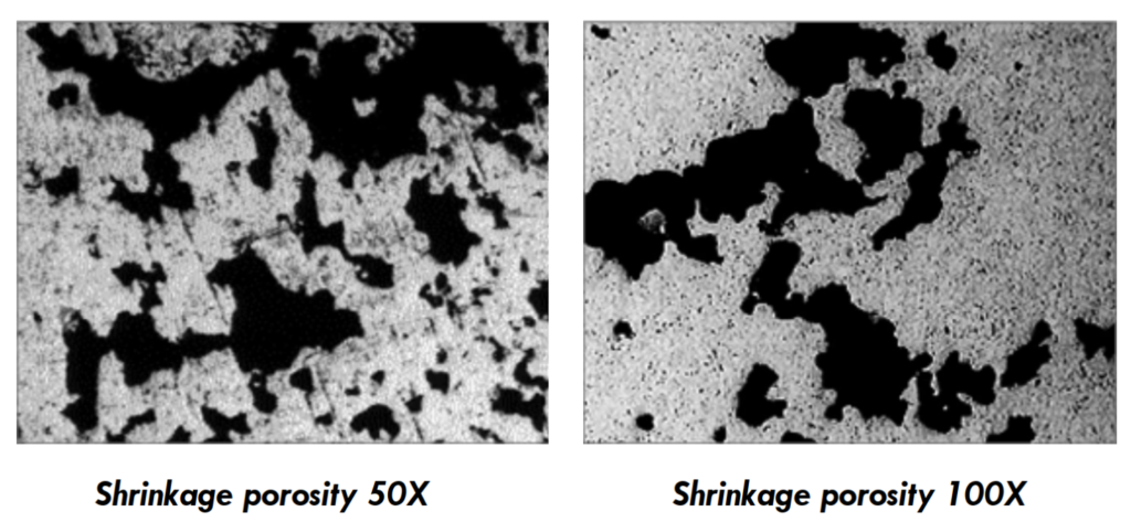
Shrinkage porosity
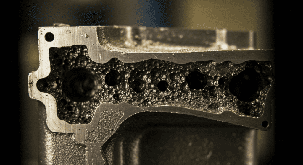
Shrinkage porosity forms when molten metal contracts during solidification and is not adequately fed with additional liquid metal. This type of porosity is usually irregular in shape and concentrated in thicker sections of the casting.
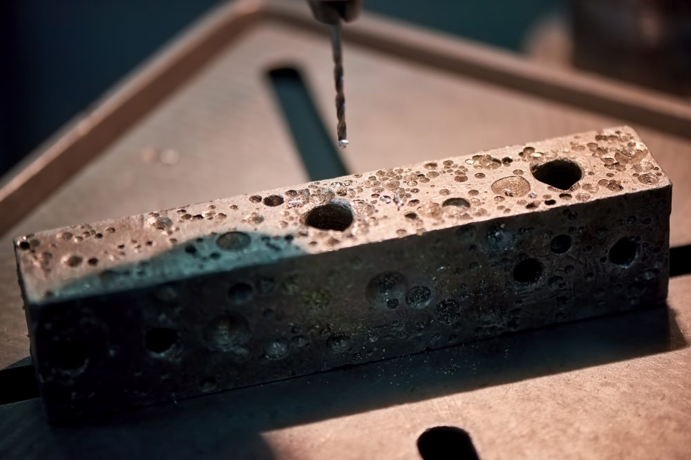
Shrinkage Porosity in Die Casting
A typical example is a structural bracket with varying wall thickness. If the thicker area solidifies last without sufficient metal feeding, internal voids develop. These voids reduce load-bearing capacity and can cause cracks under stress.
Air entrapment
Air entrapment is closely related to gas porosity but is driven mainly by poor metal flow behavior. When molten metal enters the die cavity too fast or with turbulent flow, air becomes trapped in pockets and corners.
This type of porosity is often associated with sharp changes in wall thickness, poorly positioned gates, or insufficient venting. In pressure-tight components such as pump housings, air entrapment can result in leakage even when the surface finish appears acceptable.
Solidification-related porosity
Solidification-related porosity develops due to uneven cooling rates within the die. Areas that cool too quickly may freeze off metal flow paths, preventing proper feeding of adjacent regions that are still solidifying.
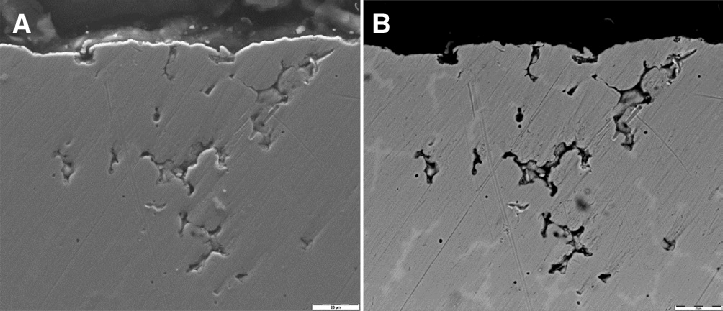
Surface and subsurface interdendritic porosity formed during solidification
This type is frequently seen near ribs, bosses, or intersections where thermal gradients are difficult to control. For example, a die-cast gearbox cover may show porosity near reinforced ribs because these features alter heat flow and metal feeding patterns.
How each type affects part performance differently
Each porosity type influences the final component differently:
- Gas-related porosity tends to affect surface quality and pressure tightness
- Shrinkage porosity mainly reduces mechanical strength and fatigue resistance
- Air entrapment increases the risk of leakage and internal cracking
- Solidification-related porosity compromises dimensional stability and local strength
Because these effects vary, treating all porosity as a single defect often leads to ineffective solutions. Successful die casting operations focus on identifying the dominant porosity type and adjusting design, process parameters, or inspection methods accordingly.
Main Causes of Porosity
Porosity in die casting rarely comes from a single source. In most cases, it develops from a combination of design limitations, process conditions, and material quality. Identifying the dominant cause requires looking at the entire casting system rather than isolated parameters.
Die design issues
Die design plays a decisive role in how molten metal flows, fills, and solidifies. Poorly designed runners, gates, and flow paths can create turbulence and dead zones where air and gases remain trapped.
Several design-related factors contribute to porosity:
- Unbalanced metal flow that causes uneven filling of the cavity
- Abrupt changes in wall thickness that disrupt smooth solidification
- Poor gate placement that forces the metal to change direction suddenly
For example, a housing with thick bosses fed through a narrow gate often shows shrinkage porosity in those bosses because the metal supply is restricted during solidification.
Improper venting and vacuum problems
Effective venting allows air and gases to escape before the cavity fills with metal. When vents are undersized, blocked, or poorly located, trapped air has nowhere to go.
Porosity linked to venting and vacuum issues often results from:
- Inadequate vent depth or length
- Clogged vents caused by soldering or debris buildup
- Vacuum systems that activate too late or fail to maintain sufficient pressure
In high-pressure die casting of automotive components, weak vacuum performance frequently leads to gas porosity near sealing surfaces, even when other process parameters appear stable.
Melt quality and trapped gases
The condition of the molten metal strongly influences porosity formation. Contaminants, oxides, and dissolved gases increase the likelihood of void formation as the metal solidifies.
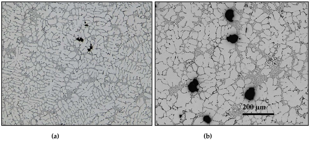
Porosity Formation in Aluminum-Based Alloys
Melt-related contributors include:
- Excess hydrogen or other dissolved gases in aluminum alloys
- Oxide films formed during improper handling or excessive agitation
- Recycled material with inconsistent cleanliness
A common example is increased porosity after introducing a higher percentage of return scrap without adjusting melt treatment practices.
Injection speed and pressure imbalance
Injection parameters determine how smoothly and completely the cavity fills. Incorrect speed or pressure settings can introduce turbulence or leave areas underfilled during critical stages.
Porosity linked to injection control is often associated with:
- Injection speeds that are too high, leading to air entrapment
- Speeds that are too low, causing premature solidification
- Insufficient intensification pressure during final solidification
For thin-walled electronic enclosures, even small deviations in shot profile can shift porosity from harmless internal areas to functional surfaces.
Temperature control
Both melt temperature and die temperature affect metal flow and feeding behavior. When temperatures fall outside the optimal range, porosity becomes more likely.
Temperature-related influences include:
- Melt temperature that is too low, reducing fluidity
- Excessively high melt temperature, increasing gas absorption
- Uneven die temperature creates inconsistent cooling rates
Inconsistent die heating often explains why porosity appears in the same location, cycle after cycle.
Alloy composition and contamination
Different alloys respond differently to solidification and gas absorption. Alloying elements, impurities, and trace contaminants all affect porosity sensitivity.
Key considerations include:
- Alloy formulations with wide freezing ranges
- Presence of iron, sodium, or other impurities beyond specification
- Moisture contamination introduced during storage or handling
For example, certain aluminum alloys used for structural parts are more prone to shrinkage porosity and require tighter process control compared to cosmetic-grade alloys.
Understanding these causes allows manufacturers to move beyond trial-and-error adjustments and focus on targeted improvements that reduce porosity at its source.
Effects of Porosity on Die Cast Parts
The presence of porosity directly influences how a die-cast component performs in service. While some porosity may be acceptable in non-critical areas, uncontrolled or excessive porosity often leads to functional problems, higher rejection rates, and long-term reliability concerns. The impact becomes more severe as performance requirements increase.
Reduced mechanical strength
Porosity interrupts the continuity of the metal structure, reducing its ability to carry a load. Internal voids act as stress concentrators, making parts more susceptible to cracking and fatigue failure.
Several performance issues arise from this condition:
- Lower tensile and yield strength compared to fully dense material
- Reduced fatigue life under cyclic loading
- Higher risk of fracture in thin or highly stressed sections
For example, porosity in suspension or mounting brackets can lead to early failure when subjected to vibration and repeated loading.
Poor pressure tightness
Pressure tightness is essential for components such as pump housings, valve bodies, and fluid control parts. Porosity that connects to the surface creates leak paths that compromise sealing performance.
In practice, this often leads to:
- Failure during pressure or leak testing
- Inconsistent sealing behavior under operating pressure
- Field failures caused by slow fluid or gas leakage
Even small interconnected pores can cause rejection in parts designed for hydraulic or pneumatic systems.
Surface defects and finishing problems
Surface porosity affects both appearance and downstream finishing processes. Small surface voids may not be visible in the raw casting but become evident after machining, painting, or plating.
This type of porosity commonly results in:
- Pits and blisters after coating or anodizing
- Uneven surface texture that affects cosmetic quality
- Increased rework or scrap during final inspection
In consumer-facing products such as appliance housings, visible surface porosity often leads to rejection despite acceptable structural performance.
Impact on machining, coating, and welding
Porosity complicates secondary operations by creating unpredictable material behavior. During machining, voids can cause tool chatter, edge breakage, or dimensional inaccuracies.
Manufacturers often encounter:
- Poor thread strength in tapped holes
- Coating adhesion failures due to trapped gases
- Difficulty achieving sound welds near porous regions
For instance, porosity near a machined sealing face may only appear after final machining, resulting in costly scrap at a late production stage.
Long-term durability and failure risks
Over time, porosity can accelerate degradation mechanisms such as corrosion and fatigue. Voids allow moisture, chemicals, or gases to penetrate deeper into the material, increasing the rate of damage.
This leads to:
- Faster corrosion initiation and propagation
- Reduced resistance to thermal cycling
- Unexpected failure after extended service life
In structural and safety-related applications, these long-term effects make porosity control a key reliability concern rather than a cosmetic issue.
Understanding these effects highlights why porosity must be addressed early in design and process planning. Prevention is far more effective and economical than correcting failures after production.
Methods to Prevent Porosity in Die Casting
Preventing porosity requires a disciplined approach that combines good design practices, stable process control, and consistent material quality. Since porosity often develops from multiple interacting factors, effective prevention focuses on reducing risk at every stage of the die casting process rather than relying on corrective actions after defects appear.
Optimizing die and gate design
Well-designed dies promote smooth metal flow and controlled solidification. Proper runner layout and gate placement reduce turbulence and help feed areas that are prone to shrinkage.
Key design considerations that support porosity reduction are:
- Balanced runner systems that deliver metal uniformly
- Gate locations that minimize abrupt flow direction changes
- Gradual wall thickness transitions that support proper feeding
For example, relocating a gate closer to a thick boss can significantly reduce shrinkage porosity by maintaining metal pressure during solidification.
Proper venting and vacuum systems
Efficient venting allows air and gases to escape before the cavity fills completely. When paired with vacuum assistance, venting becomes even more effective in reducing gas-related porosity.
Successful venting strategies focus on:
- Vents positioned at the final fill locations
- Adequate vent depth to release air without metal flash
- Vacuum systems that activate early and maintain stable pressure
In high-integrity automotive castings, vacuum-assisted die casting is often used to meet strict pressure-tightness requirements.
Controlling melt cleanliness and degassing
Clean molten metal reduces the likelihood of gas and oxide-related porosity. Melt handling practices play a critical role in maintaining metal quality from the furnace to the shot sleeve.
Effective melt control typically involves:
- Regular degassing to reduce dissolved gases
- Skimming and filtering to remove oxides and inclusions
- Controlled use of return scrap to maintain consistency
For aluminum die casting, proper hydrogen control through degassing has a measurable impact on reducing internal porosity levels.
Adjusting injection parameters
Injection speed and pressure must be carefully matched to part geometry and alloy behavior. Stable and repeatable shot profiles reduce turbulence and ensure adequate feeding during final solidification.
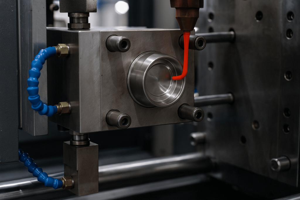
Injection Speed and Packing Pressure Impact Mold Quality
Process adjustments often focus on:
- Smooth transition from slow shot to fast shot phases
- Injection speeds that fill the cavity without excessive air entrapment
- Sufficient intensification pressure to compensate for shrinkage
In thin-walled electronic housings, fine-tuning the shot profile often shifts porosity away from functional areas.
Temperature management strategies
Consistent temperature control supports predictable metal flow and solidification. Both melt temperature and die temperature must remain within defined limits.
Effective temperature management involves:
- Maintaining melt temperature within the alloy’s optimal range
- Uniform die heating to reduce thermal gradients
- Local cooling or heating to control solidification timing
Poor temperature balance is a common reason why porosity appears in repeatable locations on otherwise stable processes.
Process monitoring and quality control practices
Continuous monitoring helps detect conditions that lead to porosity before defects occur. Data-driven process control allows faster response and more consistent quality.
Strong quality systems rely on:
- Real-time monitoring of shot parameters
- Regular inspection of vents and vacuum performance
- Statistical process control to track trends over time
Facilities that combine process monitoring with periodic X-ray inspection often achieve more predictable porosity control and lower scrap rates.
By applying these prevention methods together, manufacturers can significantly reduce porosity risk and achieve stable production without sacrificing productivity.
Conclusion
Porosity in die casting occurs due to a combination of metal flow behavior, solidification dynamics, material quality, and process control limitations. While it cannot be completely eliminated in most high-pressure die casting operations, its impact can be managed through informed design decisions, stable processing conditions, and consistent monitoring. Understanding the different types of porosity and their causes allows manufacturers to address problems at the source rather than reacting to defects after production.
Effective porosity control relies on prevention rather than correction. Optimized die design, proper venting and vacuum systems, clean melt practices, and disciplined process control help balance quality requirements with production efficiency. When these elements work together, manufacturers can achieve reliable part performance while controlling costs and maintaining competitive output rates.