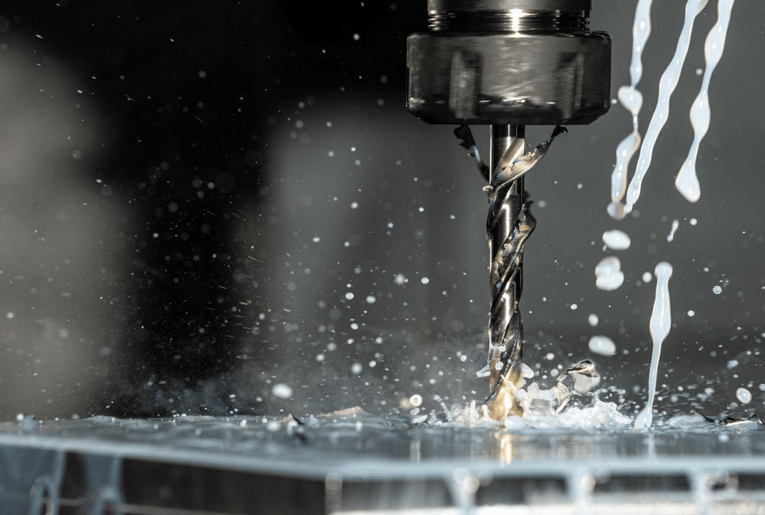
Thin-walled components are parts where one or more wall sections are significantly thinner relative to the overall size of the component. These features are common in aerospace, medical, automotive, and precision industrial applications, where weight reduction, airflow, or compact design is critical. While CNC machining allows these parts to be produced with high accuracy, thin walls introduce a unique set of challenges that do not exist in more rigid geometries.
thin-walled parts by CNC milling
The most common issues when machining thin-walled parts include deformation during cutting, vibration-induced chatter, and loss of tolerance after the part is released from the fixture. This article focuses on proven machining strategies that help control distortion, maintain accuracy, and preserve part integrity.
What is Distortion in Thin-Walled Machining
Before any cutting strategy or fixture design is considered, it is important to understand what makes thin-walled parts behave differently during machining. Distortion is not a random outcome. It is the predictable result of how thin material reacts to cutting forces, heat, and stress release. When these factors are not accounted for early, even a well-programmed CNC process can produce inaccurate parts.
What Defines a Thin-Walled Component
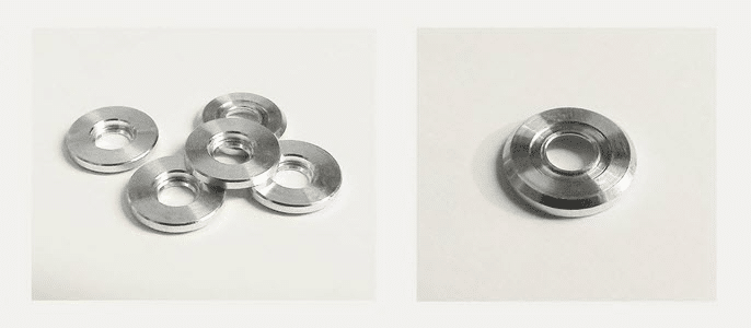
A thin-walled component is generally defined by a wall thickness that lacks sufficient stiffness to resist machining forces. While there is no universal thickness threshold, problems typically begin when the wall thickness becomes small relative to its height or unsupported length. For example, a 2 mm wall on a tall aerospace rib behaves very differently from a 2 mm wall on a short, boxed structure.
Thin walls are common in parts such as turbine housings, electronic enclosures, medical implants, and lightweight structural frames. In many of these applications, the wall thickness is dictated by functional requirements rather than machinability, leaving little margin for error during cutting.
Why Thin Walls Deform During CNC Machining
Thin walls deform because they cannot absorb cutting forces the same way thicker sections can. As the cutting tool engages the material, lateral forces push the wall away from the tool path. The thinner and taller the wall, the greater the deflection.
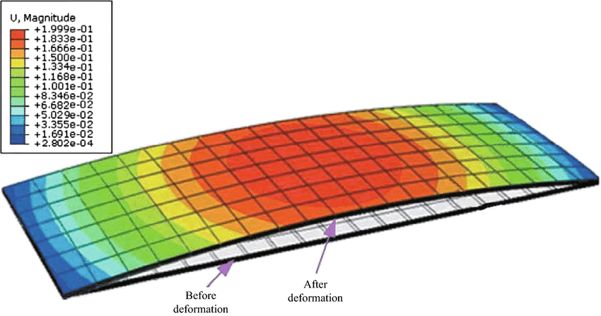
Machining distortion in a thin-walled plate
In practical terms, this means the tool may cut less material than programmed during roughing, then remove more material than expected during finishing. I have seen cases where a wall measured within tolerance while clamped, but shifted out of tolerance by several tenths of a millimeter once the part was unclamped. This behavior is not caused by programming errors, but by elastic deformation during machining.
Effects of Cutting Forces, Vibration, and Thermal Buildup
Three primary factors contribute to distortion in thin-walled parts:
- Cutting forces that push or pull the wall during engagement
- Vibration and chatter that amplify wall movement
- Heat buildup that causes localized expansion
When cutting forces fluctuate, the wall flexes repeatedly, which can lead to uneven material removal. Vibration makes this worse by introducing dynamic loads that the wall cannot dampen. Heat adds another layer of complexity. Thin sections heat up quickly and cool unevenly, which can alter dimensions even after machining is complete.
For example, when machining a thin aluminum enclosure at high spindle speeds without adequate chip evacuation, localized heating can cause the wall to expand during cutting and shrink afterward, resulting in undersized features.
Common Distortion Problems in Thin-Walled Parts
Distortion usually appears in predictable forms. The most common issues include:
- Wall deflection during cutting, leading to uneven thickness
- Tapered walls caused by progressive deflection along the tool depth
- Spring-back after unclamping, where the wall returns to a different shape
- Loss of flatness or parallelism in adjacent features
These issues often become visible only during finishing or final inspection. By that stage, correcting them may require reworking the entire part or scrapping it altogether.
Importance of Planning Before Material Removal Begins
Effective thin-wall machining starts long before the first toolpath is generated. Planning must account for how material removal will change the stiffness of the part at every stage. Removing too much material too early can destabilize the remaining structure and make later operations unpredictable.
A common mistake is fully roughing all pockets before addressing thin features. In contrast, a planned approach may leave additional stock on thin walls, allowing the surrounding material to support them until the final stages. This type of sequencing reduces stress release and improves dimensional consistency.
Understanding distortion at this level sets the foundation for all subsequent decisions, from toolpath sequencing to workholding and inspection. Without this awareness, even advanced machining strategies struggle to deliver reliable results.
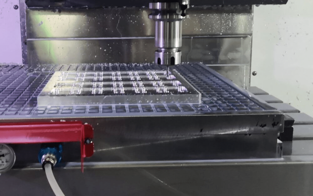
Toolpath Sequencing for Stability and Stress Control
Once distortion mechanisms are understood, toolpath sequencing becomes one of the most effective ways to control them. The order in which material is removed has a direct impact on part stiffness, internal stress release, and dimensional stability. Poor sequencing can weaken the part too early, while a well-planned sequence maintains support until the final stages.
Roughing Versus Finishing in Thin-Walled Parts
Roughing and finishing must be clearly separated when machining thin walls. Roughing operations should focus on removing bulk material while preserving structural strength. Finishing should be reserved for the final passes, once the part is adequately supported and stresses are largely relieved.
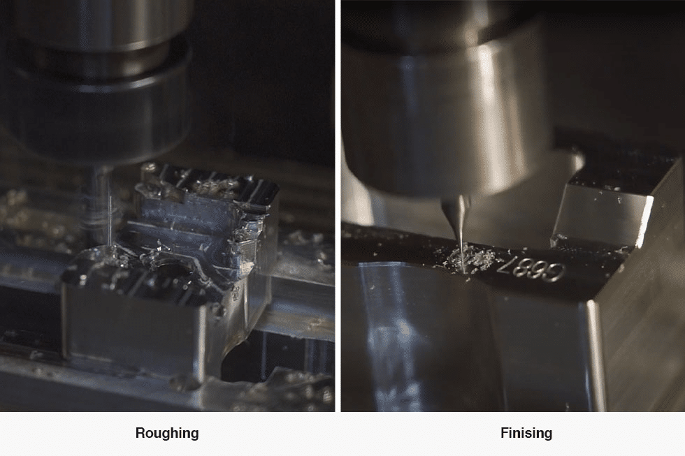
Roughing vs. Finishing in CNC Machining for Perfect Parts
In practice, this often means leaving more stock on thin walls than on thicker features. For example, leaving an extra 0.3 to 0.5 mm on a thin aluminum wall during roughing can significantly reduce deflection during finishing. This additional stock acts as temporary stiffness rather than wasted material.
Machining from Thicker Sections Toward Thinner Areas
A reliable sequencing strategy is to machine from the most rigid sections toward the least rigid ones. Thicker regions provide natural support and help absorb cutting forces as adjacent material is removed.
For instance, when machining a pocket surrounded by thin ribs, it is more stable to rough the pocket first while the ribs remain thick. The ribs can then be brought to the final thickness in later operations. This approach reduces the risk of ribs vibrating or bending during early machining stages.
Balanced Material Removal to Reduce Internal Stress
Uneven material removal can release internal stresses asymmetrically, causing the part to warp. Balanced removal helps distribute stress changes more evenly across the component.
This does not require removing equal material everywhere, but it does require avoiding aggressive cuts on one side while leaving the opposite side fully supported. Alternating passes on opposing walls or machining symmetric features in stages can significantly reduce distortion in larger thin-walled frames.
Use of Semi-Finishing and Rest Machining
Semi-finishing plays an important role in thin-wall stability. By introducing an intermediate step between roughing and finishing, the part is allowed to gradually adapt to reduced stiffness.
Rest machining is particularly useful when complex geometry leaves uneven stock after roughing. Cleaning up leftover material with light, targeted passes prevents sudden force spikes that can occur during full finishing cuts. This approach is commonly used in aerospace components where thin webs connect thicker structural nodes.
Avoiding Full-Depth Cuts Near Final Wall Thickness
Full-depth cuts close to the final wall thickness should be avoided whenever possible. These cuts concentrate cutting forces over a long engagement area, increasing deflection and vibration.
Instead, multiple shallow passes with consistent step-downs produce more predictable results. Although this increases cycle time slightly, it often prevents costly rework. In high-precision parts, the time saved by avoiding scrap far outweighs the added machining time.
Thoughtful toolpath sequencing transforms thin-wall machining from a trial-and-error process into a controlled operation. When stiffness is preserved and stresses are released gradually, the part remains stable throughout machining, setting the stage for accurate finishing and reliable inspection results.
Reducing Radial Engagement and Cutting Forces
After toolpath sequencing, the next major factor influencing distortion is how aggressively the tool engages the material. Thin-walled parts are highly sensitive to cutting forces, and even small increases in tool pressure can cause noticeable deflection. Reducing radial engagement is one of the most effective ways to maintain control during machining.
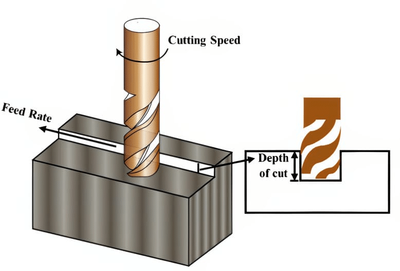
Cutting Parameter Optimization
Importance of Low Radial Engagement in Thin-Walled Features
Radial engagement directly affects lateral cutting forces. High engagement pushes the wall sideways, while low engagement allows the tool to cut with less resistance. In thin sections, reducing radial engagement helps the wall maintain its shape during cutting.
In practical terms, this means avoiding wide step-overs near thin walls. For example, when finishing a 1.5 mm aluminum wall, using a 5 to 10 percent tool diameter step-over can significantly reduce deflection compared to a conventional 40 percent step-over.
High-Speed Machining and Adaptive Clearing Strategies
High-speed machining strategies are particularly effective for fragile geometries. Adaptive clearing maintains a consistent tool load by adjusting tool engagement dynamically. This prevents sudden force spikes that can bend thin walls.
Adaptive strategies are commonly used in titanium and aluminum aerospace parts where thin ribs must be machined accurately. By maintaining a constant chip load, the tool cuts smoothly, and the wall experiences less vibration and force variation.
Smaller Step-Overs and Controlled Axial Depths
Combining small step-overs with controlled axial depths creates a stable cutting environment. While deeper axial cuts are acceptable in rigid areas, thin walls benefit from shallow axial engagement.
A balanced approach often includes:
- Light radial engagement to reduce lateral force
- Moderate axial depth to maintain cutting efficiency
- Consistent chip thickness throughout the pass
This combination allows material to be removed predictably without overstressing the wall.
Tool Selection for Reduced Tool Pressure
Tool geometry plays a critical role in minimizing cutting forces. Sharp tools with high helix angles reduce cutting resistance and improve chip evacuation. Tools designed for finishing thin features often produce cleaner cuts with less pressure on the wall.
For example, switching from a general-purpose end mill to a high-helix finishing tool can noticeably reduce chatter when machining thin stainless steel enclosures. Tool wear must also be monitored closely, as dull tools increase cutting force and heat.
Managing Heat to Prevent Thermal Distortion
Heat buildup can cause thin walls to expand during machining and contract afterward, leading to dimensional errors. Controlling heat is just as important as controlling cutting forces.
Effective methods include using appropriate coolant flow, ensuring chips are evacuated quickly, and avoiding prolonged tool contact in one area. In high-precision work, even short dwell times at the end of a toolpath can create localized heating that affects wall thickness.
By reducing radial engagement and carefully managing cutting forces and heat, thin-walled parts remain stable throughout machining. This approach not only improves accuracy but also extends tool life and produces more consistent surface quality.
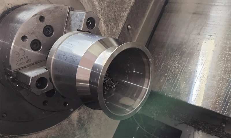
Workholding Strategies for Fragile Geometries
Even with optimized toolpaths and reduced cutting forces, poor workholding can undermine the entire machining process. Thin-walled parts are especially vulnerable to distortion caused by excessive or uneven clamping. Effective workholding must secure the part while allowing it to behave naturally under cutting loads.
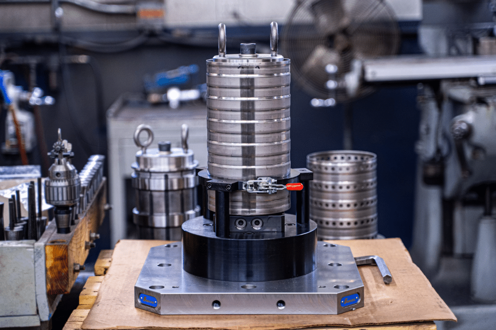
CNC Workholding for Thin-Walled Parts
Risks of Over-Clamping Thin-Walled Components
Over-clamping is a common cause of hidden distortion. Excessive clamping force can deform thin walls during machining, only for the part to shift shape once it is released. This often leads to parts that measure correctly in the fixture but fail inspection afterward.
Typical problems caused by over-clamping include:
- Permanent wall deformation near clamping points
- Loss of parallelism after unclamping
- Localized dents or pressure marks
These issues are frequently misattributed to cutting parameters when the root cause is fixture design.
Use of Soft Jaws and Custom Fixtures
Soft jaws allow the clamping surface to match the part geometry more closely, distributing force over a larger area. This reduces localized stress and improves part stability.
Custom fixtures are often justified for thin-walled production parts, especially in aerospace and medical applications. For example, a contoured fixture supporting the outer profile of a thin housing can prevent wall collapse while still providing access for internal machining.
Vacuum Fixtures for Uniform Support
Vacuum workholding is particularly effective for flat or shallow thin-walled components. Instead of point clamping, vacuum fixtures apply a uniform holding force across the surface.
Vacuum systems work well for parts such as thin plates, covers, and electronic enclosures. However, they require careful sealing and clean surfaces to maintain a consistent holding force throughout the operation.
Supporting Thin Walls Without Restricting Movement
Thin walls need support, but they should not be fully constrained. Over-restraining the part can lock in stress and lead to distortion once machining is complete.
Effective support strategies include:
- Backing thin walls with sacrificial material during roughing
- Using temporary supports that are removed before finishing
- Supporting internal features with expandable mandrels or inserts
These methods provide stability while still allowing the part to relax naturally.
Machining in Multiple Setups to Reduce Stress
Multiple setups can help distribute machining stress more evenly. By dividing operations across setups, no single stage removes too much material at once.
For example, roughing internal pockets in one setup and finishing external thin walls in another allows the part to stabilize between operations. This approach is common in precision housings where dimensional accuracy is critical.
Verifying Stability Before Final Finishing
Before final finishing passes, part stability should be verified. This may include lightly probing critical surfaces or performing a low-force test pass to observe deflection.
Taking the time to confirm stability at this stage often prevents final tolerance issues. In thin-walled machining, small adjustments to clamping or support can make the difference between a conforming part and a rejected one.
Proper workholding completes the foundation for distortion control. When the part is securely supported without excessive constraint, cutting strategies can perform as intended and deliver consistent, accurate results.
Inspection and Verification of Thin-Walled Parts
After machining is complete, inspection plays a critical role in confirming whether distortion has been successfully controlled. Thin-walled parts can appear accurate during machining but shift subtly once released from the fixture. A structured inspection approach helps detect these issues early and ensures consistent quality.
Inspection and Verification of Thin-Walled Parts
Measuring Wall Thickness Without Inducing Deformation
Measuring thin walls requires care, as excessive probing force can deform the part and produce misleading readings. Contact-based tools must be used with controlled force, especially on unsupported features.
Common practices include:
- Using low-force micrometers or calipers designed for thin sections
- Supporting the wall during measurement to prevent bending
- Avoiding repeated measurements at the same location
In high-precision work, even slight pressure from a standard caliper can alter the reading on a thin aluminum wall.
In-Process Inspection to Detect Early Distortion
In-process inspection allows distortion to be identified before the part reaches its final form. Checking dimensions after key machining stages helps determine whether the part is reacting as expected.
For example, probing a thin rib after semi-finishing can reveal early deflection trends. If variation is detected at this stage, toolpaths or support methods can be adjusted before final finishing, reducing the risk of scrap.
Probing and Non-Contact Measurement Methods
On-machine probing is widely used to verify critical dimensions without removing the part from the fixture. Probing allows immediate feedback and reduces the influence of unclamping-related distortion.
Non-contact methods such as laser scanning or optical measurement are especially useful for very thin or flexible features. These techniques eliminate measurement force entirely and are often used in aerospace and medical manufacturing, where tolerance requirements are strict.
Comparing Nominal and Actual Geometry During Machining
Comparing measured values to nominal geometry after each critical step provides insight into how the part is behaving under stress. Deviations that increase progressively often indicate cumulative distortion rather than isolated errors.
This comparison is particularly valuable in complex thin-walled structures, such as lattice-reinforced housings, where localized distortion may not be obvious until it affects adjacent features.
Final Inspection and Quality Validation
Final inspection should confirm not only dimensional accuracy but also overall part stability. Measurements should be taken after the part has fully relaxed, preferably after a short period at room temperature.
Best practices include:
- Verifying wall thickness, flatness, and parallelism
- Inspecting critical features in their free state
- Documenting inspection results to refine future processes
Consistent inspection feedback closes the loop between machining strategy and real-world performance. For thin-walled parts, this feedback is essential for continuous improvement and long-term process reliability.
Conclusion
Successfully machining thin-walled parts without distortion requires a disciplined and deliberate approach at every stage of the process. Distortion is largely controlled through proper planning, thoughtful toolpath sequencing, reduced cutting forces, and workholding methods that support the part without over-constraining it. When each decision is made with part stiffness and stress behavior in mind, thin-walled features can be machined accurately and repeatably.
Equally important is inspection, which validates whether these strategies are working as intended. In-process checks and careful final measurement help identify subtle deformation before it becomes a quality issue. When machining strategy and inspection work together, thin-walled components can meet tight tolerances consistently, even in demanding applications.