Resistance welding (RW) encompasses a range of fusion welding techniques that achieve coalescence through a mix of heat and pressure. The heat is produced at the junction which has to be welded by electrical resistance to current flow. The main elements of resistance welding are displayed in the figure below for the most popular method in the group, a resistance spot-welding operation. Workparts to be welded (often sheet metal parts), two opposing electrodes, a way to press the parts between the electrodes, and an AC power source that can apply a controlled current are the components. In spot welding, the process creates a fused zone between the two components known as a weld nugget.
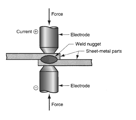
Resistance welding doesn't require shielding gases, flux, or filler metal like arc welding does, and the electrodes that carry the electrical power are non-consumable. RW is categorized as fusion welding since the faying surfaces melt virtually invariably when heat is applied. There are certain exceptions, though. In order to prevent fusion, certain resistance heating-based welding techniques employ temperatures lower than the melting points of the base metals.
The resistance welding process involves several key variables, such as electrode properties, welding current, electrode force, and current duration. Resistance welding is an effective and quick welding process since it requires a current that might be ten to one hundred times larger than that of arc welding, although the actual welding time is usually less than a second.
Power Source and Heat Generation in RW
In resistance welding (RW), the circuit resistance, the current flow, and the length of the current application all affect the heat energy required for welding. The following mathematical expression represents this relationship:
H = I2 Rt
where �� is the heat generated in joules (to convert to Btu, divide by 1055); �� is the current in amperes; �� is the electrical resistance in ohms; and �� is the time in seconds.
Resistance welding processes frequently involve very high currents (5000 to 20,000 A) with relatively low voltages (usually below 10 V). In most procedures, the current duration (t) is small; for example, in a standard spot-welding operation, it might last 0.1 to 0.4 seconds. Since the resistance in RW is very low (around 0.0001 V) and the squared part in the equation above magnifies the effect of current, a large current is employed. The combination of the resistances of the workpieces, the electrodes, the contact resistances between the electrodes and the workpieces, and the contact resistance of the feeding surfaces results in resistance in the welding circuit. Therefore, heat is produced in each of these electrical resistance zones. Since the preferred site of the weld is at the faying surfaces, it is optimal for them to have the biggest resistance in the sum. Using metals like copper, which have extremely low resistivities, reduces the resistance of the electrodes. In order to disperse the heat produced there, the electrodes are frequently cooled with water. The workpart resistances are determined by the part thickness and the resistivities of the base metals. The size, shape, and contact areas of the electrode, as well as the surface conditions (such as the electrode's scale and the cleanliness of the work surfaces), determine the contact resistances between the electrodes and the parts.
Ultimately, surface finish, hygienic conditions, contact area, and pressure all affect the resistance at the faying surfaces. There shouldn't be any impurities to keep the contact surfaces apart, such as paint, oil, or dirt.
Pressure is just as important to resistance welding success as heat. In resistance welding (RW), the main purposes of pressure are to press the faying surfaces together to achieve coalescence once the correct welding temperature has been reached and to force contact between the two work surfaces and the electrodes before the current is applied.
Advantages and Disadvantages of Resistance Welding
Resistance welding is a common option for industrial applications because of its many benefits. Its efficiency and speed, which enable large production rates, are two main advantages. Filler metals are not needed for the process, and because the heat is localized, there is less chance of adjacent components bending. Resistance welding is also excellent for automation, which makes it perfect for large-scale manufacturing. Because the heat can be precisely regulated, the resulting welds are robust, exact, and precise. This approach is also more cost-effective because it requires less finishing work and less energy than many others, and it is safer than many others because it emits no fumes or sparks.
Resistance welding does, however, have several disadvantages. Some operations may find it difficult to obtain the necessary equipment because it is often costly and specialized. It restricts the kinds of metals that can be welded by only working with materials that have a high electrical resistance. Due to the confined heat, large pieces are difficult to weld, and accurate component alignment is essential to prevent weak joints. Heat-induced uneven expansion or contraction of materials can lead to distortion, which can potentially be a problem. Resistance welding is still a useful technology in many manufacturing contexts, despite these difficulties.
Major Resistance Welding Processes
The three major resistance welding processes of commercial importance are resistance spot welding (RSW), resistance seam welding (RSEW), and projection welding (RPW).
Resistance Spot Welding (RSW)
Resistance Spot Welding (RSW) is the most common method in its class and is used extensively in the mass manufacturing of appliances, cars, metal furniture, and other sheet metal products. The economic significance of resistance spot welding becomes clear when one considers that the average car body has approximately 10,000 spot welds and that the annual production of automobiles reaches tens of millions worldwide.
Resistance spot welding (RSW) is a method of RW in which opposing electrodes fuse the faying surfaces of a lap joint at a single location. This method is applied to sheet metal components that have a thickness of 3 mm (0.125 in) or less when an airtight assembly is not needed. A sequence of spot welds is used to join the components. Although round electrodes are the most frequent electrode form, square, hexagonal, and other shapes can also be employed, the electrode tip determines the size and shape of the weld spot.
The resulting weld nugget is usually between 5 and 10 mm (0.2 and 0.4 in) in diameter, and the base metals are slightly beyond the nugget where the heat-affected zone extends. The weld's strength should be comparable to the surrounding metal if it is produced correctly. The following figure illustrates the steps involved in a spot-welding cycle.
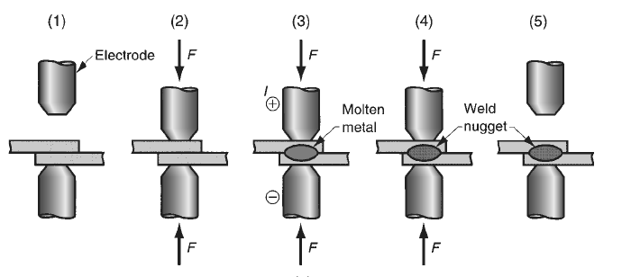
Two primary categories of materials are utilized to make RSW electrodes: alloys based on copper and compositions of refractory metals, like copper and tungsten. The greater wear resistance of the second group is well-known. In spot welding, as in most production processes, the tooling gradually ages with use. The electrodes are made with internal water-cooling passages if possible. Spot welding can be done with a variety of tools and techniques due to its extensive industrial use. The apparatus consists of portable spot-welding guns as well as press- and rocker-arm style spot-welding machines. The rocker-arm spot welders include an upper electrode that is movable and may be lifted and lowered to facilitate loading and unloading work. The lower electrode remains stationary. The upper electrode is fixed to a rocker's arm—thus the name—whose motion is managed by the worker's foot pedal.
Force and current throughout the welding cycle can be controlled by programming in modern equipment. Spot welders with presses are meant for heavier jobs. A vertical press driven by hydraulic or pneumatic power produces a straight-line motion for the upper electrode. Larger forces can be used thanks to the press action, and complicated welding cycles can typically be programmed using the controls. The task is brought to the preceding two machine types, which are both stationary spot welders. It is challenging to transfer and position the part into stationary machinery for massive, heavy tasks. Portable spot-welding guns come in a range of sizes and combinations to suit these situations. Two opposed electrodes held within a pincer mechanism make up these devices. Because each item is lightweight, either an industrial robot or a human worker may grasp and operate it. Flexible electrical cables and air hoses are used to link the cannon to its own power and control source. If necessary, a water hose can also be used to supply water cooling for the electrodes. Spot welding car bodies is a common task for mobile spot-welding guns in auto assembly factories. Although humans still operate some of these guns, industrial robots are now the technology of choice.
Resistance Seam Welding (RSEW)
Resistance Seam Welding (RSEW) is a technique that produces a sequence of overlapping spot welds along a lap joint by employing rotating wheels rather than stick-shaped electrodes as in spot welding. This procedure, which is shown in the figure below, is frequently employed in the production of sheet metal containers, car mufflers, and gasoline tanks because it produces airtight joints. Although spot welding and RSEW are essentially identical, RSEW involves additional complexity because of the wheel electrodes and the continuous aspect of the operation.
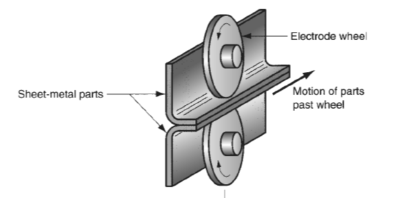
The continuous operation in RSEW means that the seams must be along a straight or uniformly curved line, as sharp corners and discontinuities can pose challenges. Additionally, warping of the parts is a greater concern, necessitating fixtures to hold the workpieces in place and minimize distortion.
The application of the weld current and the motion of the electrode wheels in RSEW determine the distance between the weld nuggets. In the most popular technique, called continuous motion welding, the appropriate spacing between spot welds is achieved by periodically pulsing the current as the wheels revolve at a constant speed. Overlapping weld areas are typically the result of this configuration. On the other hand, a process known as roll spot welding allows gaps to appear between the weld spots if the current frequency is decreased. Alternatively, a continuous weld seam can be achieved by maintaining a constant welding current. The figure below shows these variations.

Another RSEW variation is intermittent motion welding, in which each spot weld is produced by the electrode wheel stopping on a regular basis. The spacing between the weld areas is determined by the wheel's movement between stops, resulting in patterns resembling those in Figures (a) and (b) above.
While electrode wheels are used in place of stick-shaped electrodes, seam-welding machines are similar to press-type spot welders. During RSEW, cooling is frequently required for the workpiece as well as the electrode wheels. Water is usually directed onto the top and underside of the workpiece surfaces in the vicinity of the electrode wheels to accomplish this cooling.
Resistance Projection Welding (RPW)
Resistance projection welding (RPW) is a resistance welding process where coalescence occurs at small, predetermined contact points on the parts to be joined. These contact points can be projections, embossments, or localized junctions that are built into the parts themselves. For instance, when joining two sheet-metal components together, the top component may be constructed with recessed edges that come into first contact with the bottom component, as shown in the Figure below. The cost reductions from welding can balance the embossing procedure, despite the appearance of it adding to the part's cost.
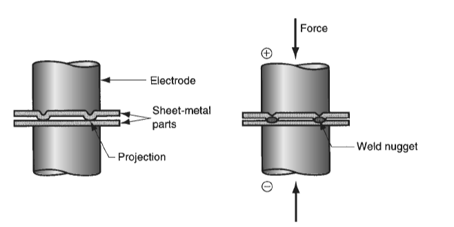
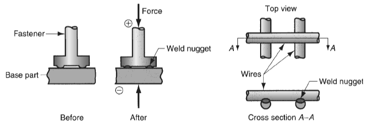
Resistance projection welding comes in two variations, which are depicted in the figure below. One variation allows RPW to permanently link fasteners with shaped or machined projections to a sheet or plate, making future assembly procedures easier. For the fabrication of welded wire items like shopping carts, stove grills, and wire fences, another version known as cross-wire welding is employed. The round wires' touching surfaces act as projections in this process, helping to localize the resistance heat needed for welding.
Other Resistance Welding Operations
In addition to the main resistance welding procedures that were previously covered, the following alternative methods fall under this category and should also be acknowledged: flash welding (FW), upset welding (UW), percussion welding (PEW), and high-frequency resistance welding (HFRW).
Flash Welding (FW)
Flash welding (FW) is predominantly used for butt joints. The process entails bringing the surfaces that need to be welded close together and heating them to the point of melting using electric current. Depending on the degree of surface contact, this process involves arcing, sometimes referred to as flashing. FW is therefore occasionally included in the arc-welding group. The surfaces are forced together to produce the weld after heating, which frequently calls for additional machining to guarantee consistent joint dimensions. FW is used in high-speed, economical processes including connecting wire ends in wire drawing and butt welding steel strips in rolling mills.
Upset welding (UW)
Similar to FW, upset welding (UW) combines the heating and pressing phases into a single process cycle. In contrast to FW, UW heats just by electrical resistance at the contacting surfaces—arcing not included. Upon reaching a temperature below the melting point, the faying surfaces coalesce under increased pressure, which causes the materials at the contact region to become disturbed. While UW shares several applications with FW, such as joining wire, pipes, and tubes, it is not exactly a fusion-welding technique like some of the others mentioned.
Percussion welding (PEW)
Similar to FW, percussion welding (PEW) uses incredibly short weld cycles—between one and ten milliseconds—in its operation. When electrical energy is abruptly released between surfaces that need to be joined, rapid heating results. The components are then fused together by applying a percussion force. For electronic applications where compact size and adjacent components that are sensitive to heat are essential, PEW's localized heating is perfect.
High-Frequency Resistance Welding (HFRW)
High-frequency alternating current is used in High-Frequency Resistance Welding (HFRW) to heat the metal surfaces before an upsetting force is applied to finish the weld. This technique, which operates at frequencies ranging from 10 to 500 kHz, guarantees that the skin effect of the high-frequency current concentrates the heat at the weld joint. In a comparable procedure called High-Frequency Induction Welding (HFIW), an induction coil is used to create current instead of making direct electrical contact. For continuous welding tasks, like joining the longitudinal seams of metal pipes and tubes, HFRW and HFIW are suitable. These techniques are useful for a variety of industrial processes due to their capacity to produce consistent, high-quality welds in high-speed manufacturing situations.
References
Groover, M.P., 2010. Fundamentals of Modern Manufacturing: Materials, Processes, and Systems. 4th ed. Hoboken, NJ: John Wiley & Sons, Inc.


