The desire for perfect 90° corners in metal parts creates massive engineering headaches. Sharp corners become stress concentration points, leading to part failure, scrapped components, and production delays.
Sharp corners in CNC machining should generally incorporate a minimum radius of 1/3 the wall thickness to prevent stress concentration. For optimal results, internal corners should have a radius equal to or greater than the cutting tool diameter, while external corners can achieve sharper definitions with proper tooling.
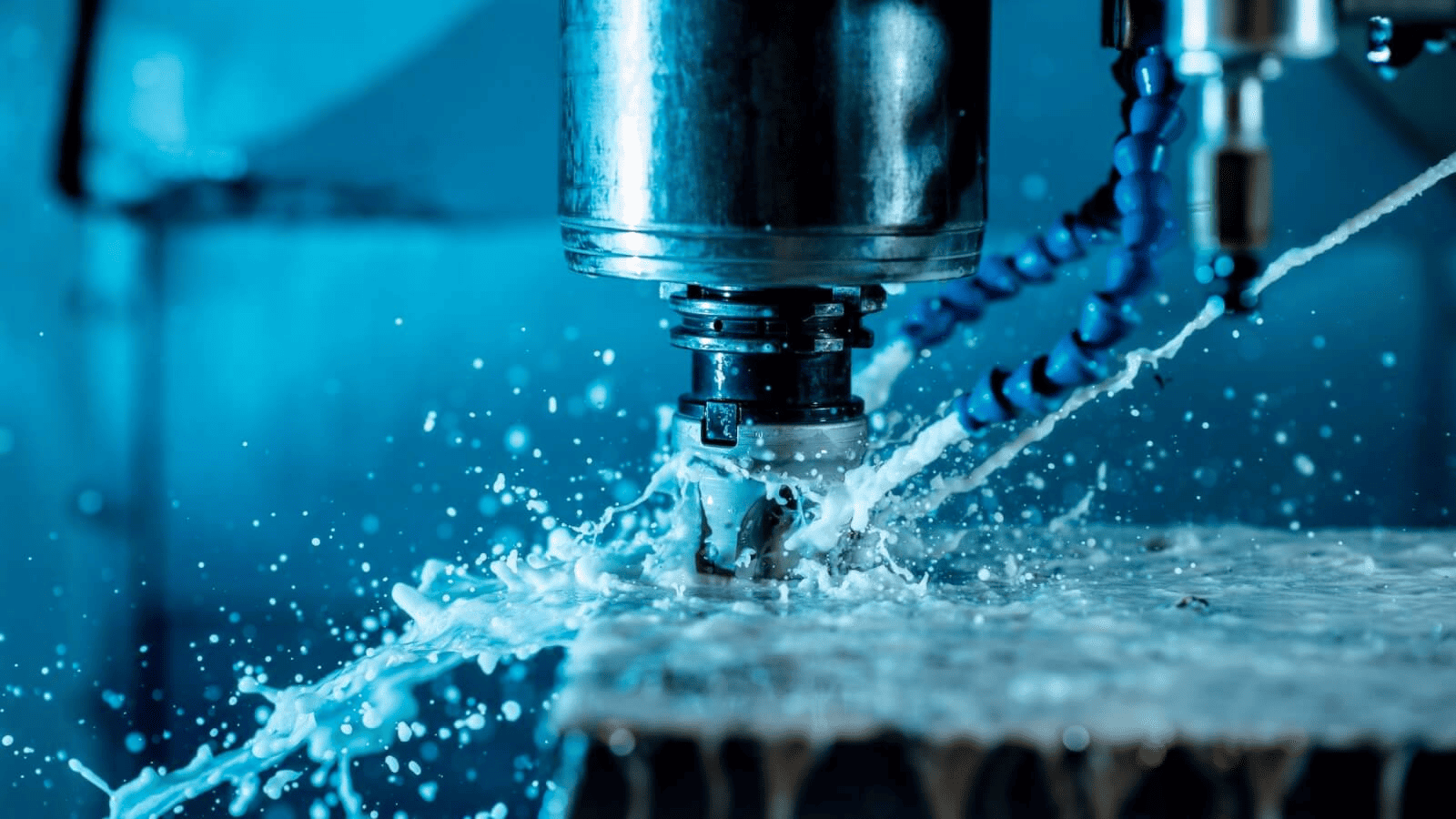
CNC-machined part showing proper corner design
When designing parts for CNC machining, corner design might seem like a minor detail, but it can make or break your project. I've seen countless engineers spend weeks perfecting complex features only to have their parts fail because they neglected proper corner design. Let's explore the critical aspects of corner design that will save you time, money, and frustration.
Why Do Sharp Corners Lead to Stress Concentration in Metal Components?
The sharp 90° corner you've specified in your CAD model is causing part failures during testing. Your production timeline is in jeopardy, and the engineering team is scrambling to understand why supposedly "simple" parts keep breaking.
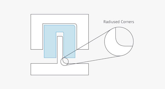
Sharp corners act as stress concentration points where forces converge and multiply, often reaching 3-5 times the nominal stress level. Adding appropriate radii distributes these forces over a larger area, dramatically reducing peak stress and preventing crack initiation. For most applications, a minimum corner radius of 1/3 the wall thickness serves as a good starting point.
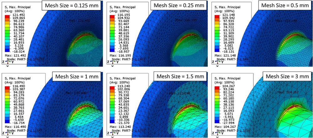
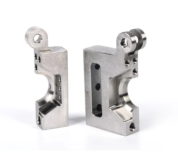
FEA analysis showing stress concentration at a sharp corner
To understand why sharp corners are so problematic, we need to examine the physics of stress distribution in materials. When force is applied to a component with a sharp corner, the stress doesn't have sufficient area to disperse, creating what engineers call a stress singularity point.
This concentration effect follows an inverse square relationship—as the radius approaches zero (a perfectly sharp corner), the theoretical stress approaches infinity. While real-world materials don't experience infinite stress, the multiplication effect is significant enough to cause premature failure.
In my experience working with automotive components, I've seen parts with sharp internal corners fail at loads just 40% of their designed capacity. By implementing a radius equal to the wall thickness, we increased load-bearing capacity by over 200% in critical applications.
The mathematical relationship between corner radius and stress concentration is described by the stress concentration factor (Kt):
| Corner Radius Ratio (r/t) | Approximate Kt Value | Stress Multiplication |
|---|---|---|
| 0 (sharp corner) | Theoretically infinite | >5x nominal stress |
| 0.1 | 3.0 | 3x nominal stress |
| 0.3 | 1.8 | 1.8x nominal stress |
| 0.5 | 1.5 | 1.5x nominal stress |
| 1.0 | 1.2 | 1.2x nominal stress |
Where r is the corner radius and t is the wall thickness. This table demonstrates why the 1/3 rule works as a practical minimum for most applications.
How Does Material Choice Affect Corner Machining Strategies?
Your aluminum prototype machined perfectly, but switching to stainless steel for production has resulted in tool breakage and poor corner quality. The material change is threatening your launch schedule and budget.
Material properties significantly impact corner machining strategies. Softer materials like aluminum allow for smaller corner radii (down to 0.5mm), while harder materials like stainless steel and titanium require larger radii (1.0-1.5mm minimum) to prevent tool deflection and chatter. Material-specific cutting speeds, feeds, and tool selection are essential for achieving optimal corner quality.
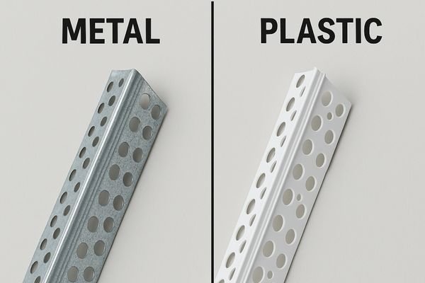
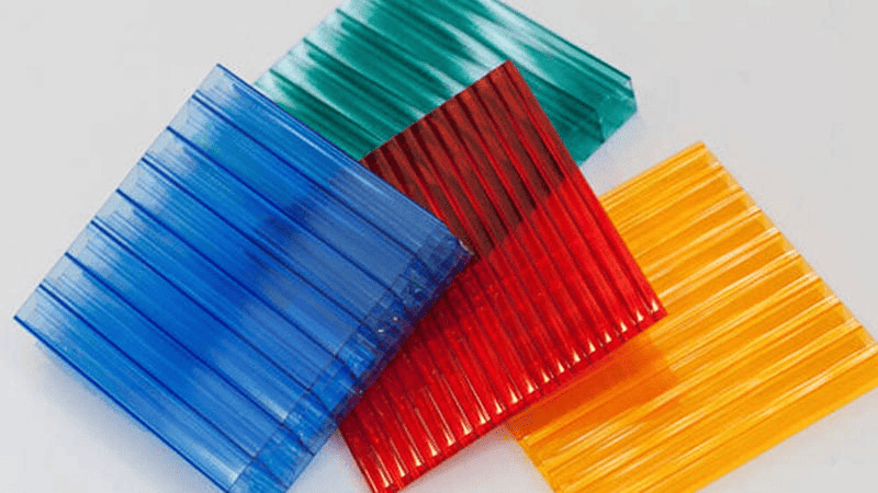
Comparison of corner quality in different materials
Material characteristics dictate numerous aspects of CNC corner machining strategy. Beyond simple hardness measurements, properties like work hardening tendency, thermal conductivity, and microstructure all influence how corners should be approached.
Take titanium alloys, for example. Their poor thermal conductivity causes heat to concentrate at the cutting edge, accelerating tool wear. When machining internal corners in titanium, I've found success using a strategy of progressive corner roughing with decreasing tool sizes, maintaining a higher engagement angle to distribute cutting forces. This approach extends tool life by up to 300% compared to direct corner machining with a single tool.
For work-hardening materials like stainless steel, corner entry strategy becomes critical. Traditional approaches like plunging directly into corners can work-harden the material, making subsequent passes increasingly difficult. Instead, using helical interpolation to gradually engage the corner reduces work hardening and improves surface finish quality.
The relationship between material properties and recommended minimum corner radii:
| Material Type | Hardness Range | Min. Internal Corner Radius | Tool Considerations |
|---|---|---|---|
| Aluminum | 40-95 HB | 0.5-0.8mm | Higher speeds, carbide tools |
| Mild Steel | 120-180 HB | 0.8-1.2mm | Moderate speeds, coated tools |
| Stainless Steel | 150-290 HB | 1.0-1.5mm | Lower speeds, specialized coatings |
| Titanium | 300-400 HB | 1.5-2.0mm | Very low speeds, rigid tooling |
| Hardened Steel | 45-60 HRC | 2.0-3.0mm | CBN or ceramic tools |
These recommendations assume standard machining conditions; specialized setups may achieve tighter corners in specific applications.
What Corner Design Specifications Are Critical for Medical and Semiconductor Applications?
Your vacuum chamber design has been rejected by the customer because internal corner radii don't meet cleanliness requirements, and trapped particles could contaminate sensitive processes. The revision cycle is costing you valuable time and reputation.
For high-purity applications, internal corner design must eliminate potential particle traps. Medical components require minimum radii of 0.5-1.0mm with Ra surface finish values below 0.8μm to prevent bacterial growth. Semiconductor vacuum chambers demand even larger radii (typically 3.0-6.0mm) with electropolishing to achieve particle-free environments. Documentation of corner specifications is essential for regulatory compliance.
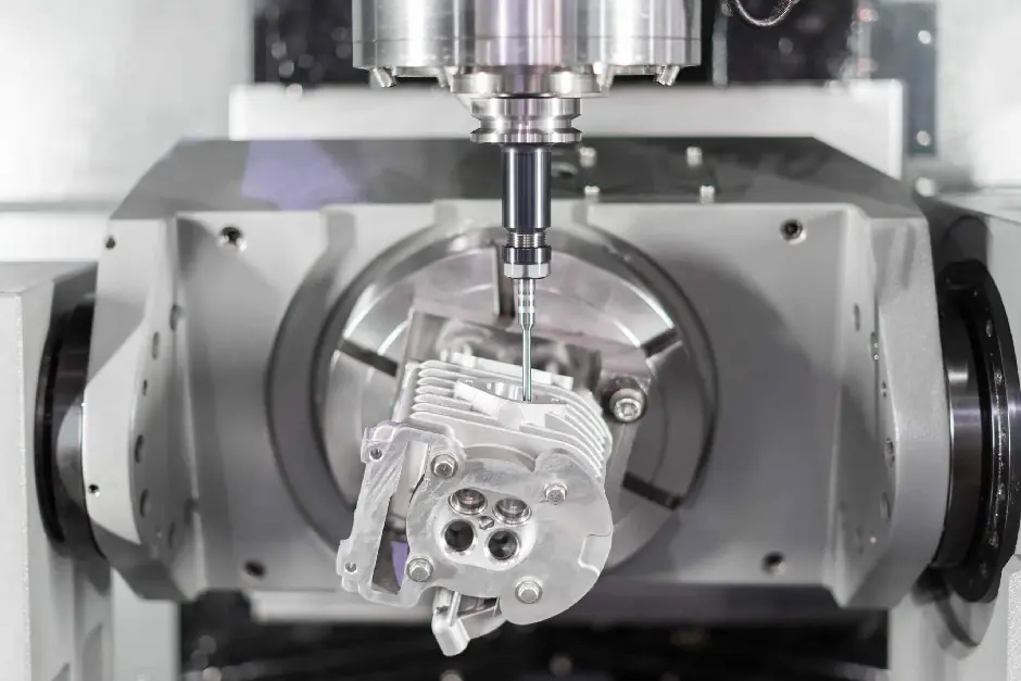
Medical-grade part with optimized corner design
High-precision industries have special requirements for corner design that go beyond basic structural considerations. In medical device manufacturing, corners represent potential harbors for bacteria and contaminants. The FDA's guidance on cleanable design specifically addresses corner geometry as a critical factor in device safety.
When I designed surgical instrument trays, we implemented what we called "flow corners" – specially designed transitions with compound radii that not only distributed stress effectively but also improved cleaning solution flow dynamics. These corners featured primary radii of 3mm with secondary blend radii of 1mm, creating a geometry that allowed cleaning solutions to maintain laminar flow around corners while still being machinable on our 5-axis systems.
In semiconductor applications, corner design affects both cleanliness and gas flow dynamics. Vacuum chambers we produce incorporate corner radii calculated based on the mean free path of gas molecules at operating pressures. This approach minimizes virtual leaks and turbulence, creating more stable process conditions.
Key corner design specifications for specialty applications:
| Application | Primary Concern | Recommended Design | Validation Method |
|---|---|---|---|
| Medical Implants | Biocompatibility | Minimum 0.5mm radius, mirror finish | SEM examination |
| Surgical Instruments | Cleanability | Compound radii, 1-3mm primary | Dye penetration testing |
| Pharmaceutical Equipment | Bacterial prevention | 3mm+ radii, electropolished | Riboflavin testing |
| Semiconductor Chambers | Particle generation | 6mm+ radii with progressive blends | Particle counting |
| Optical Components | Light interaction | Application-specific geometry | Interferometry |
These specifications must be balanced against functional requirements, but maintaining these minimum standards ensures compliance with industry expectations and regulatory requirements.
Conclusion
Proper corner design in CNC machining is a critical balance between engineering principles and manufacturing constraints. By following material-specific guidelines and understanding application requirements, you'll achieve components that perform reliably while remaining cost-effective to produce.