Introduction
A thread is, by definition, a helical ridge that has been carved using a machining technique that advances uniformly with each spindle revolution. On various surfaces of a cylinder or cone, the helical ridge has a consistent section. It can develop on the surface of a nut (internal) or a screw or bolt (external). The main job of a thread is to couple two mechanisms together. When you consider the cap on your water bottle, a wonderful image of threads will come to mind.
A tight water seal is created by the coupling of the cap and bottle top. As a result of the connection, motion is transmitted. The motion can therefore be used to achieve mechanical benefits.
Important Terms Used in Threading
The terminology indicated below are those used in threads, as seen in the diagram below.

- Major diameter. -It is the internal or exterior screw thread's maximum diameter. This diameter designates the screw. It is often referred to as the nominal or outer diameter.
- Minor diameter. -It is the internal or exterior screw thread's smallest diameter.
Additionally known as core diameter or root diameter.
- Pitch diameter. - It is the diameter of a hypothetical cylinder on a cylindrical screw thread, whose surface would pass through the thread at positions where the width of the thread and the width of the intervals between the threads would be equal. Another name for it is an effective diameter.
- Pitch. - It is the separation between a point on one thread and its comparable position on the next. Between equivalent positions in the same axial plane, this is measured in the axial direction.
- Lead. - It measures the separation between two identical locations on the same helix. It can alternatively be explained as the distance a screw thread moves axially during a nut rotation. In the case of single-start threads, lead is equal to the pitch. It is double the pitch in double-start threads, triple the pitch in triple-start threads, and so on.
- Crest. - The thread's upper surface is what it is.
- Root. - It is the bottom surface that the thread's two neighboring sides have produced.
- The thread's depth. - The perpendicular distance between the crest and root is what it measures.
- Flank. - This area connects the crest and root.
- Thread angle. - It is the angle that the thread's sides cover.
- Slope. - It has a thread pitch that is half that.
Thread Position
Nearly every sensible location for the turned or milled item may accommodate a thread. Everything is fine as long as equipment can get to the place where the thread will go. Even though threading placement seems to have few limitations, it is vital to take the depth of an internal thread into account.
To finish the procedure, we might need to drill through the hole from both sides if the thread depth is more than the tooling's maximum depth. There are three different kinds of holes you may use on turned items to accept internal threads:
- On-axis: Holes that originate at one end and extend straight through the center of a turned component.
- Axial: Holes that begin at one end of a part but do not exactly pass through the middle.
- Radial: openings that rip across the outer arc of a rotated component
Internal Threads
On a concave surface, a screw thread is referred to as an internal (female) machining thread.

A threading tool with a single lip is used to manufacture these kinds of threads.
The standard threading tap is employed in several internal threads. On components produced by CNC machining, a tap is a metal tool used to cut internal threads. To screw a piece of work together, you need an internal thread. On internal threads, thread cutting can be done manually or mechanically using taps. To cut an internal thread, you'll need the following equipment:
- Twist drill
- 900 countersinks
- Internal tap
- versatile tap wrench (for hand taps)
- Box column drilling or by hand (for machine taps)
- eye protection
The diameter of the hole that you require must first be determined. The correct tap must also be used during cutting, which is another crucial step. In terms of nominal sizes, internal machining taps are categorized. A punch is used to center the thread before cutting it. In order to drill a core hole, use the twist drill next. In order to chamfer the core hole, the 900 countersink is used. Once the tap is in the tap wrench and inserted into the core hole, the thread may now be cut.
External Threads
The term "screw thread" is also used to describe an exterior thread. Screws, plug gage, bolts, and studs are some examples of frequent external threads.

For sections that may be turned, an external thread may run the whole length of the component. Lathe threading is particularly efficient for external threads. Using a circular die, you may alternatively cut by hand. Typically, a fixed die stock contains the die. Manufacturers use circular dies in place of internal threads. Hexagonal square dies are also available. For interlocks, these kinds of dies work well. They support the restoration of cases and the transportation of dead to difficult locations. You can cut an external thread using the tools listed below:
- Round die and rod
- File
- Die stock
- Vise
- Flat-tip screwdriver
- Cutting spray
The circular rod's edges must first be filed. Then, at 450, chamfer the rod. The chamfer should be a tiny bit larger than the thread's depth. The circular die may then be securely fixed using a clamp. To cut the thread, the rod has to be under a lot of pressure. Cutting sprays aid in enhancing the surface quality of the component while increasing its lifespan.
Alternatives to Threading: Inserts
For most metal components, threading is the ideal method of creating a solid connection during element assembly. This band is insufficient for weak materials like plastic and aluminum however. In this situation, inserts are useful. Plastic components with specific coil inlays will provide extended application life. This makes it possible to use strong threads on porous materials. At essence, you may plan a hole in the desired area and add inserts later. For the installation of your insert, we shall grind the hole.
Infeed Methods
The motion from one pass to the next is referred to as infeed. There are three fundamental approaches to feeding threads:
- The radial infeed
- the compound or flank infeed
- the modified compound (flank) infeed
Radial Infeed
If the conditions allow it, radial infeed is one of the more popular threading techniques. It is used in conjunction with a perpendicular cutting action that reduces the diameter. The Z-axis start point does not change when the X-axis is defined for each threading pass diameter. For soft materials, like brass, specific grades of aluminum, etc., this infeed technique is appropriate. In tougher fabrics, it could harm the thread integrity and is not advised. Both insert edges are operating concurrently as a natural result of a radial infeed action. Due to the opposing orientation of the insert edges, chips form at both edges simultaneously, leading to issues that can be linked to high temperatures, a lack of coolant access, and tool wear issues. A compound infeed technique will typically fix the issue if the radial infeed produces a thread of subpar quality.
The Compound or Flank infeed
The compound infeed approach, sometimes referred to as the flank infeed method, operates according to a distinct principle. Trigonometric calculations are used to move the location for each pass to a new Z-position instead of feeding the threading tool perpendicularly toward the part diameter. This method produces a threading pass where the majority of the cutting occurs at one edge. Since just one insert edge does the majority of the work, the tool's life is increased since the heat produced may drain away from the edge of the tool while the cutting chips curl away. For the majority of threads, the compound threading technique allows for a heavier pass depth with fewer passes. In order to reduce rubbing, compound infeed can be modified by leaving a 1-to-2-degree gap on one edge. The threading insert's angle will help to keep the thread at the desired angle.
Threading Operations
Cutting the threads of pieces makes screwed connections possible. Internal threads are necessary for connections with full screws. For many of these connections, complementary external threads are also required as a counterpart. A key working skill for single-piece manufacturing is the ability to cut threads. Additionally, it is required for repairs. The following are CNC machining methods for thread cutting:
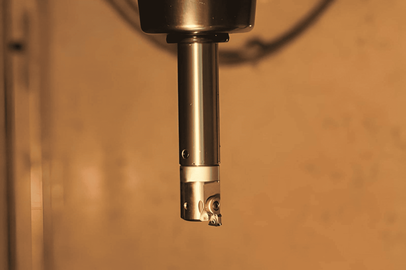
i. Milling

This technique makes use of a milling cutter that rotates. The cutter's design follows the intended thread shape. CNC machine shops utilize either a single cutter or a number of cutters.
All of the cutting edges are present in one plane with single cutters. On the many cutters, however, there are numerous rows of annular cutting teeth. To cut the threads, a hob can also be used. The cutter's teeth in this scenario will be arranged in a helix. Threads can be created internally or externally by precision cnc milling. The milling technique produces threads that are highly accurate. When the thread's pitch is too coarse for a die, this approach is preferred. Many machinists believe cnc precision milling to be more efficient than lathe threading. The most effective way to create pieces like lead screws is by milling. The quick manufacturing and excellent precision are to blame for this. Additionally, milled items can be finished in just one or two passes.
ii. Lathe Threading
Thread cutting on a lathe is a significant threading procedure. A workpiece that has undergone this technique will have a helical ridge. The portion of the helical ridge on the part is uniform. Using a threading toolkit, threading a lathe requires many cuts. Using a lathe machine to tap is one of the most used techniques. Clamping the workpiece in the lathe chuck is done by the machinist. For smaller and bigger taps, a dead center or a spring loader center, both of which clamp to the tailstock, is then employed. The tap is then turned using the handle that comes next. Utilizing a die handle is an additional typical technique. For cutting exterior threads on a lathe, it is a great option.

Conclusion
A thorough grasp of production procedures is necessary to produce parts of the highest quality.
The cutting of threads by machines is a crucial step in the production process. It may appear a bit hard, but it is not a good idea to give up on the concept.
If you have any unique insights on thread processing, please leave a comment, we will reply to you as soon as possible.