
Have you ever reamed or drilled material to a specific depth? If yes, then you would be familiar with the holes as well. In engineering, different types of machining operations are used and the most common is hole-making.
Out of all the engineering operations, almost 20% involve the use of holes in the manufacturing industry. Whether you have to state the diameter or put a specific mark on a material, a hole is a perfect way to do that.
In this article, you’ll learn how holes are used in engineering drawings and what are its different types. So, let’s dive into the article!
What are Holes in Engineering?
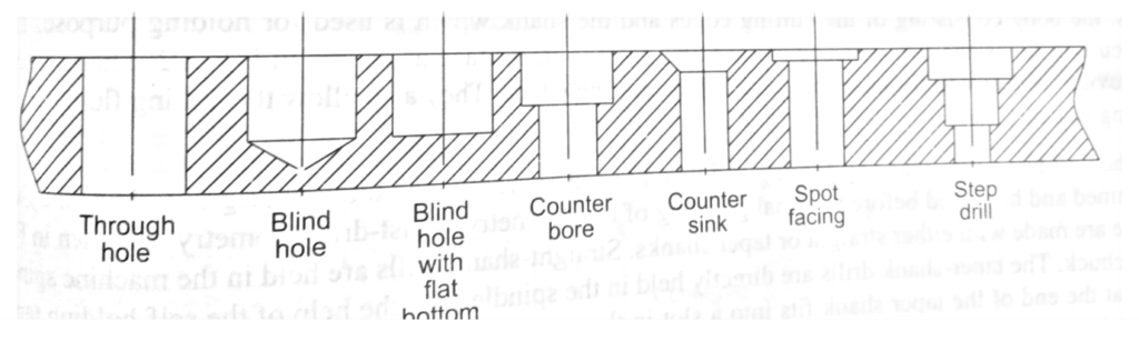
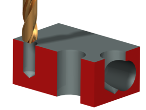
In engineering, a hole is a circular feature created by a rotating cutting tool. In this field, the hole can be either a through hole or a blind hole. A through hole is a complete hole that you can see on both sides of the object, while a blind hole is only milled or drilled to get a specific depth. One can not see a blind hole from the other side of the object.
Moreover, the hole has the same diameter and geometry as its cutting tool. However, most of the holes in engineering have the same basics, yet they can be different from each other. The reason why they are different is that they all are used for a specific purpose, and the change in geometry and diameter can affect their usage.
What Features to Consider while Creating Holes?
To know which type of tool is required to create a specific hole, it is important to understand the features one is looking for. The three major parameters are discussed as under:
1. Depth
As discussed earlier, a blind hole is a hole that has a specific depth. It can have a flat bottom or pointed end due to the ending point of the tool. Moreover, the depth of the hole entirely depends upon the length of the cutting tool.
- Diameter
The diameter of any hole depends upon the tool that creates it. Holes can have different diameters. There are standard available sizes from which one can select the preferred one. The sizes vary from 0.0019 inches to 3 inches. Apart from this, there are other standard sizes available, including letter, metric, fractional, and number sizes.
Moreover, One can also create a custom size if there is a need for a non-standard diameter. However, if the budget is low, it is recommended to opt for a standard-sized tool as custom sizes can cost more.
3. Tolerance
The accuracy of the hole depends upon various factors, including the tolerance of the hole. Some of them are the vibration and sharpness of the tool or the chips buildup of the material.
The tolerance of the hole will determine the type of process of the hole making. The reason why tolerance plays an important role in the hole-making process is some processes are specified for tight tolerance holes.
What are the Various Types of Holes in Engineering?
In general, machining or manufacturing industries rely on the use of holes for various purposes. Therefore, hole-making is not restricted to only a specific hole. It has a broad range and consists of different types for different operations.
There are twelve types of holes, and three of them are most commonly used. Let’s have a look at them below.
1. Simple Hole
Definition
As shown by the name, a simple hole is simply a circle that is cut out in the shape of the material or object. The circle or block is then used for various engineering purposes. For instance, you can use it for fastening or connecting the parts of the material.
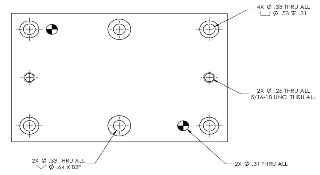
Callout Symbol
To make the hole drawings more convenient, different callout symbols are taken for different types of holes. Similarly, the callout symbol for the simple hole is a diameter ‘Ø symbol. Look at the image below to illustrate it better.

Use
Now, you are familiar with the name of the simple hole and its symbol as well. However, the question is how you can use it in the field of engineering and other manufacturing processes. Here are the most common uses of the simple hole that shows its importance:
- It helps in creating various hole features in the model
- You can specify the location of any object
- It assists in measuring the dimensions of a material
2. Blind Hole
Definition
Just like a simple hole, the blind hole also has its use in manufacturing work. Although it is a type of hole but differs from other types by not completely going through the material. What does it mean to not go into the material?
It simply means you can mile or drill the blind hole only to a specific depth without interrupting the other sides of the object under construction. Hence, it does not break through the workpiece and contains one open end and the other end closed.
Callout Symbol
The blind hole does not have a specific callout symbol. You can specify it with the diameter or depth of the workpiece used.
Use
Being the widely used type of hole in engineering, the blind hole has various applications in the manufacturing industry. Some of them are as:
- It helps in measuring the residual stresses of an object.
- Different machines like CNC milling use blind holes for operating the thread milling cycle.
- Conventional tapping, threading, and interpolation also involve the use of blind holes.
3. Through Hole
Definition
Unlike a blind hole, a through hole has the ability to completely go through the workpiece or material. It is most commonly used in electronic components and is known by the term thru-hole in the engineering industry.
Callout Symbol
The callout symbol of the through hole is similar to that of a simple hole which is the diameter ‘Ø symbol. It simply means if you have a 10-diameter hole in the material, it will be shown as ‘’Ø10 Through’’ in the drawings.
Use
Through hole has an important use in electronic components such as drilling or PCBs etc. Moreover, through-hole components are highly effective to handle the environmental stress of an object.
4. Interrupted Hole
Definition:
An interrupted hole is a type of hole that is “interrupted” by another feature. In other words, the “other feature” crosses the hole. Therefore, it is known as an interrupted hole. For this hole, machiners use a new hole-making tool that creates a sequence of coaxial holes.
However, the coaxial holes are followed by gaps in the material. Thus, the gap brokes the coaxial hole sequence. There are two moves that the tool performs at a time: the cutting and non-cutting moves. This cycle repeats till the end of the hole.
5. Spotface Hole
Definition
A spotface hole is a hole in which a specific region of the material is faced. It gives a smooth and flat surface. It is similar to the counterbore hole. However, it is shallow.
The difference between a spotface hole and a counterbore hole is that the spotface hole has a flat surface, while at the bottom, the counterbore hole has a shoulder-type surface.
Callout Symbol
The callout symbol for the spotface hole is the counterbore symbol with “SF” written inside it.
Use
In Engineering, a spotface hole is known to provide a flat and accurate surface. If casting is used to make a component, it will not have a smooth surface. Due to this reason, a spotface hole is drilled to make sure that the rough surface is connected correctly and smoothly.
6. Counterbore Hole
Definition
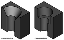
A counterbore hole is a cylindrical type of hole that has a flat bottom. It opens another coaxial hole. In other words, this hole has a larger hole above it which is linked to it. The counterbore hole is necessary because it is a standard screw hole.
Callout Symbol
The callout symbol for the counterbore hole is “⌴.“ This symbol has the diameter and depth figure.
Use
The counterbore holes are used for the socket-head screws. These holes are made when the screw has to be below the surface and not above it. Moreover, for PCBs, counterbore holes are more appropriate to use.
7. Countersink Hole
Definition
A countersink hole is a simple hole having a conical shape above it. A countersunk hole matches the angle and surface of the screw and lets the screw fit and sit below the surface. It is the opposite of the counterbore hole. It requires a lot of calculations and accuracy to drill this hole than the counterbore hole.
Callout Symbol
The callout symbol for a countersink hole is like a conical shape “⌵.”
Use
In engineering, the countersink hole is used to place a countersink screw or bolt. As the counterbore hole, countersink holes allow the screw to remain beneath the surface.
8. Counter Drill Hole
Definition
A counter drill hole is similar to a countersink hole. However, this hole has a recess on top of it. Both the counter drill and countersink holes have the same center. Nonetheless, their drilling depth is different from each other.
For the counter drill holes, it is crucial to set out the depth and diameter of the counter drill.
Callout Symbol
The symbol of the counter drill hole is the same as the countersink symbol “⌵.“ However, it has more depth than the countersink hole.
Use
As countersink holes, counter drill holes are also used for countersink screws or bolts. Moreover, these holes are also for PCBs.
9. Tapered Hole
Definition
A tapered hole is a type of hole that has a different diameter at the start and a different diameter at the end of the hole. Typically, this hole is wider from the top and narrow at the bottom.
Callout Symbol
The callout symbol of the tapered hole is a triangle that is wider from one side and narrow from the other side. It also has a line that passes through the triangle.
Use
In engineering, tapered holes have multiple uses, mostly they are used to protect the cutting tools or tool holders. Apart from this, another common usage of this hole is for bolt gathering in mechanical systems.
10. Screw Clearance Hole
Definition
A screw clearance hole is a hole that has a wider diameter as compared to the screw thread so that it can go through it without any difficulty. It has enough space to let the thread of the bolt or screw pass but not the head of the bolt or screw.
Callout Symbol
The callout symbol for a screw clearance hole is a hole with a “/” in between the hole to denote the diameter.
Use
These screw clearance holes are used when a part requires a bolt or screw to go through it. To use a screw clearance hole, it is crucial to pick the correct size. To calculate the size of the hole, add the diameter of the screw head and the screw and divide the total by two.
Moreover, to create a screw clearance hole, CNC milling machines are usually preferred.
11. Tapped Hole
Definition
A tapped hole is a hole that has threads cut inside its surface. These cuts are made through the process of tapping. The process of drilling is done before the screw is placed.
Callout Symbol
The callout symbol for this type of hole depends on the standard in which it is used. If the holes have metric standards, the diameter symbol would be “M.” This means that for an M8 bolt, the symbol would also be “M8.” For other threads, such as a UNF thread, the diameter symbol would also be “UNF.”
Use
Tapped holes are specifically designed to have a grip over threaded components. For instance, bolts, screws, and threaded rods.
12. Threaded Hole
Definition
Threaded holes are holes that have threads in them. They have a close resemblance to the tapped holes. However, their making procedure is different from each other. The major distinction between these two holes is that the tool, as well as the surface, are different.
The process of thread creates thread outside of a hole, whereas the process of tapping creates thread inside the hole.
Callout Symbol
The callout symbol for this type of hole is a hole with a “/” in the center of it. However, if the threaded holes are in metric, the symbol would be “M.” with this, the threaded depth is listed.
Use
Threaded holes are essential in machinery’s fastened parts. They are easy to use in CNC machines. When all the major elements are added, then the treads are placed in the machinery.
Frequently Asked Questions
● What is Hole Callout?
A tool used for measuring the diameter or dimensions of a hole is generally known as a hole callout. It was first made by Hole Wizard and is widely used in engineering drawings. From measuring the depth of the object to changing its dimensions, a hole callout has various applications in the manufacturing industry.
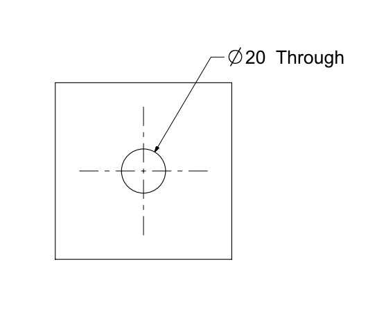
● How are Holes Shown in Engineering Drawings?
When showing holes in engineering drawings, two major factors play a vital role. The diameter and the depth of the hole. For instance, a simple hole has a diameter of 20 that goes completely into the material. You can represent it as ‘’Ø20 Through’’ and it will show up like the one shown in the figure below:
Moreover, you can also use a section view or a bottom view in order to see the hole clearly.
However, the bottom section might show different variations in different types of machine operations. This is because the shape of the bottom depends on the tool used in the hole-making operation. Following are some common bottom shapes for different hole processes:
- For drilling, the drill tip angle will determine the shape of the bottom of the hole and it will be in the form of a circular cross-section.
- During boring, the zero tip angle determines the shape of the bottom and it will be flat.
● What is a Tooling Hole?
The most important part of the Printed Circuit Board (PCB) is the tooling holes. Mounting holes or tooling holes are circular mechanical openings that find their use in design fabrication and PCB.
Tooling holes align the shape and dimension of the PCB by holding it from the bottom and through the top. In the manufacturing industry, these holes are crucial for the perfect alignment or security of the board.
Conclusion
The use of holes in engineering or the mechanical industry is mandatory for the perfect arrangement of the materials. Without hole-making operations, you cannot get the desired shape or diameter of the object under construction. Whether you are new to the field or have worked previously, the discussed-above things will be highly helpful in doing your next machining task with holes.