Gears are an essential component in machinery and play a crucial role in transmitting power and motion from one component to another. They are widely used in various applications, such as automotive transmissions, machine tools, and robotics. Gears can be classified based on different parameters, such as their shape, application, manufacturing process, and operation.
One of the most common classifications of gears is based on their configuration and application. This classification considers the arrangement of the gears and their intended use in each application. Understanding the different types of gear and their classifications is crucial in selecting the appropriate gear for a specific application. In this article, we will explore the different types of gears and their classification based on their configuration and application.

Types of Gears:
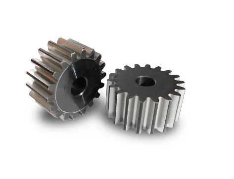
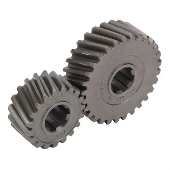
Spur Gears: Spur gears are the simplest and most common type of gear. They have straight teeth that run parallel to the gear axis, making them efficient at transmitting power but prone to noise and vibration. Spur gears are used in various applications, such as power transmission, speed reduction, and motion control. They are also available in different sizes and materials, making them suitable for a wide range of applications.
There are several types of spur gears, including:
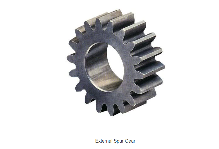
External Spur Gears:
External spur gears have teeth on the outer circumference of the gear and mesh with teeth on a mating gear. They are the most common type of spur gear and are used in many mechanical systems, including industrial machinery, automotive transmissions, and household appliances.
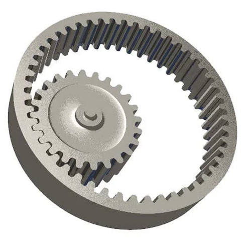
Internal Spur Gears:
Internal spur gears have teeth on the inside diameter of the gear and mesh with teeth on a mating gear. They are used in applications where space is limited or where the gear needs to be hidden from view, such as in clocks and watches.
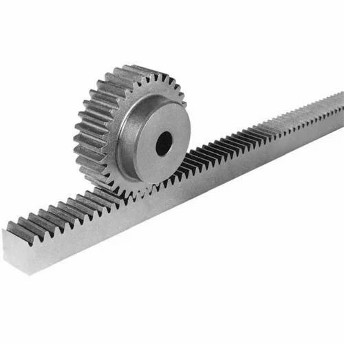
Rack and Pinion Gears:
Rack and pinion gears are a type of spur gear system that converts rotary motion into linear motion. The rack is a straight bar with teeth along one edge, while the pinion is a spur gear that meshes with the teeth on the rack. Rack and pinion gears are commonly used in steering systems, elevators, and machine tools.
Idler Spur Gears:
Idler spur gears are used to change the direction of rotation or to provide a neutral gear position in a gear train. They have no effect on the overall gear ratio and are often used in automotive transmissions and other power transmission systems.
Compound Spur Gears:
Compound spur gears are two or more spur gears mounted on the same shaft or parallel shafts. They provide a higher gear ratio than a single spur gear and are used in applications where high torque and speed reduction are required, such as in heavy machinery and construction equipment.
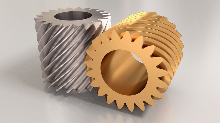
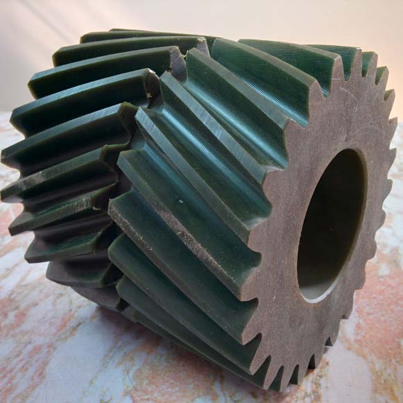
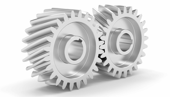
Helical Gears: Helical gears have teeth that are angled along the gear axis, providing smoother and quieter operation than spur gears. Helical gears are used in applications where low noise and high-speed operation are necessary, such as automotive transmissions and industrial machinery. They also have higher load-carrying capacity than spur gears due to their wider tooth contact area.
There are several types of helical gears, including:
Parallel Helical Gears:
Parallel helical gears have teeth that are cut at an angle and run parallel to the axis of rotation. They are used in applications where the input and output shafts are parallel to each other and where a high gear ratio is required.
Double Helical Gears (Herringbone):
Double helical gears, also known as herringbone gears, have two sets of teeth that are cut at an angle in opposite directions, providing smoother and quieter operation than parallel helical gears. They are used in applications where high torque and low noise are required, such as in heavy machinery and wind turbines.
Skew Gears:
Skew gears, also known as crossed helical gears, have teeth that are cut at an angle and run at an angle to the axis of rotation. They are used in applications where the input and output shafts are not parallel to each other and where a high gear ratio is required. Skew gears are commonly used in the aerospace industry for applications such as helicopter transmissions and turboprop engines.
Helical Rack and Pinion Gears:
Helical rack and pinion gears are a type of helical gear system that converts rotary motion into linear motion. The rack is a straight bar with teeth along one edge, while the pinion is a helical gear that meshes with the teeth on the rack. Helical rack and pinion gears provide smoother and quieter operation than straight rack and pinion gears and are used in applications such as automotive steering systems and CNC machines.
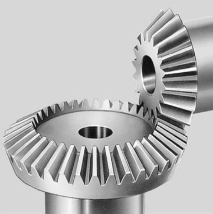
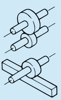
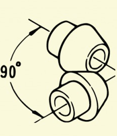
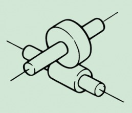
Bevel Gears:
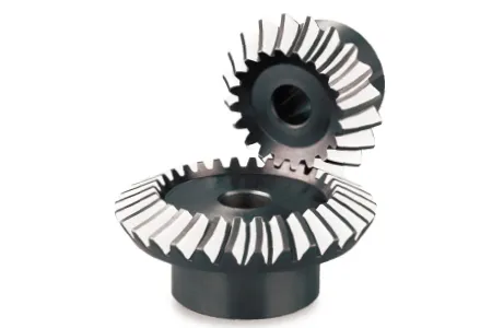
Bevel gears have conical-shaped teeth that intersect at an angle to transmit power between two intersecting shafts. Bevel gears are used in applications where the direction of motion needs to be changed by 90 degrees, such as in differential gears of vehicles and steering systems of ships.
There are several types of bevel gears, including:
Straight Bevel Gears:
Straight bevel gears have teeth that are cut straight and taper towards the gear axis. They are the simplest and most common type of bevel gear and are used for low-speed and low-torque applications. Straight bevel gears have a high degree of efficiency, making them suitable for high-precision applications.
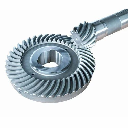
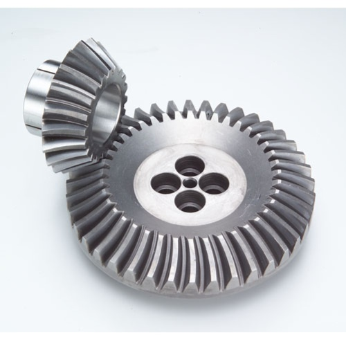
Spiral Bevel Gears:
Spiral bevel gears have teeth that are cut at an angle and spiral around the gear axis. They provide a smoother and quieter operation than straight bevel gears and are used in high-speed and high-torque applications, such as in heavy machinery and aircraft engines. Spiral bevel gears have a lower degree of efficiency than straight bevel gears but are more durable and require less maintenance.
Zerol Bevel Gears:
Zerol bevel gears have teeth that are curved and taper towards the gear axis. They are similar to straight bevel gears but have a larger tooth contact area, providing a higher load capacity and smoother operation. Zerol bevel gears are commonly used in differential gearboxes and automotive transmissions.
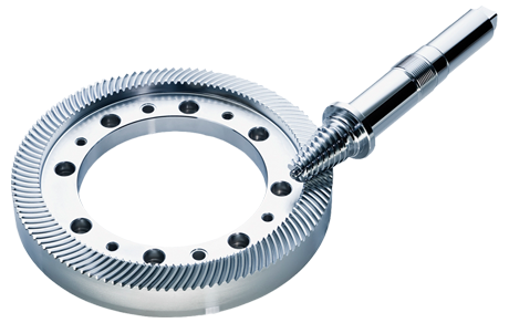
Hypoid Bevel Gears:
Hypoid bevel gears have teeth that are cut at an angle and are offset from the gear axis, providing a high torque transmission capability. They are commonly used in automotive differentials, where the drive shaft and axle shaft intersect at a right angle. Hypoid bevel gears have a low degree of efficiency due to the offset teeth but provide high torque capacity and a compact design.
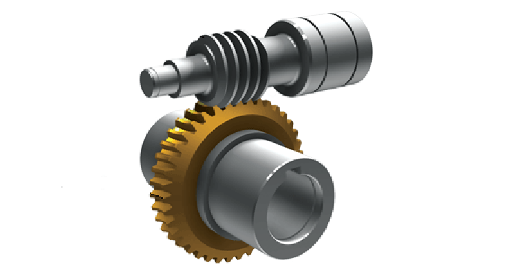
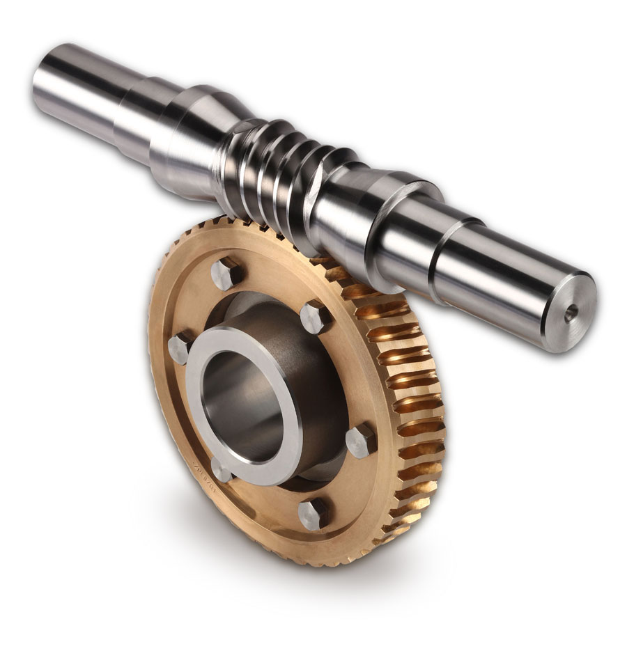
Worm Gears:
Worm gears consist of a cylindrical gear (worm) that meshes with a worm wheel. Worm gears are used in applications where high reduction ratios are required, such as in conveyor systems and elevators. They also provide a self-locking feature, which prevents back-driving of the system.
There are several types of worm gears, including:
Single Enveloping Worm Gears:
Single enveloping worm gears have a single thread worm and a gear with an enveloping tooth profile. The worm and gear mesh at a right angle, and the worm rotates the gear as it turns. Single enveloping worm gears are used in applications where high gear reduction is required, such as in machine tools and conveyor systems.
Double Enveloping Worm Gears:
Double enveloping worm gears have a double-threaded worm and a gear with an enveloping tooth profile. The worm and gear mesh at a right angle, and the worm rotates the gear as it turns. Double enveloping worm gears provide higher torque capacity and smoother operation than single enveloping worm gears and are used in applications such as robotics and aerospace.
Non-throated Worm Gears:
Non-throated worm gears have a cylindrical worm and a gear with straight teeth. The worm and gear mesh at a right angle, and the worm rotates the gear as it turns. Non-throated worm gears are used in applications where low noise and high efficiency are required, such as in packaging machinery and printing presses.
Non-Circular Worm Gears:
Non-circular worm gears have a worm with a non-circular cross-section and a gear with a complementary shape. The worm and gear mesh at a right angle, and the worm rotates the gear as it turns. Non-circular worm gears are used in applications where high gear reduction and variable speed ratios are required, such as in machine tools and robotics.
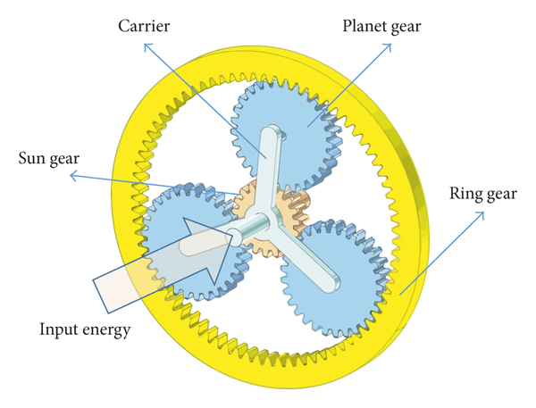
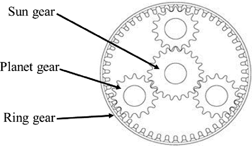
Planetary Gears:
Planetary gears consist of a sun gear, planet gears, and ring gear that rotate around a common axis. Planetary gears are used in applications where high torque and high reduction ratios are required, such as in automatic transmissions of vehicles and robotics.
There are several types of planetary gears, including:
Simple Planetary Gears:
Simple planetary gears consist of a sun gear, planet gears, and ring gear. The sun gear is located in the center and the planet gears revolve around it while engaging with the ring gear. Simple planetary gears are used in a variety of applications such as automotive transmissions, electric drills, and winches.
Compound Planetary Gears:
Compound planetary gears are similar to simple planetary gears, but they have multiple planet gear sets that share the same sun and ring gears. Compound planetary gears are used in applications where high torque and gear reduction ratios are required, such as in heavy machinery and wind turbines.
Harmonic Drive Gears:
Harmonic drive gears, also known as strain wave gears, consist of a flexible ring with internal teeth that is deformed by an elliptical cam mounted on a central shaft. The motion of the elliptical cam creates a wave-like motion that is transferred to a rigid outer ring, which has external teeth that mesh with a set of planet gears. Harmonic drive gears are used in applications such as robotics and space exploration.
Hypoid Planetary Gears:
Hypoid planetary gears are similar to simple planetary gears, but they have a hypoid offset that allows the input and output shafts to be at an angle to each other. Hypoid planetary gears are used in automotive applications such as rear-wheel drive differentials.
Classification of Gears:
Gears can also be classified based on their configuration and application. Here are some of the most common classifications of gears based on their configuration and application:
Parallel Axis Gears:
These gears have parallel axes and are the most commonly used gears in power transmission applications. Examples include spur gears, helical gears, and double helical gears (also known as herringbone gears).
Intersecting Axis Gears:
These gears have intersecting axes and are used in applications where power needs to be transmitted at a right angle. Examples include bevel gears and hypoid gears.
Non-parallel and Non-intersecting Axis Gears:
These gears have non-parallel and non-intersecting axes and are used in applications where power needs to be transmitted at a specific angle. Examples include worm gears and cross-helical gears.
Rack and Pinion Gears:
This configuration is used when linear motion is needed. The rack is a flat-toothed bar that meshes with a gear, known as the pinion.
Cycloidal Gears:
These gears are used in applications where high gear reduction ratios are required. They have a unique tooth profile that enables smooth and quiet operation.
Planetary Gears:
These gears have a central sun gear and one or more planet gears that rotate around it. They are commonly used in automotive transmissions, robotics, and other high-torque applications.
Spindle Gears:
These gears are used in machine tools for transmitting power between the spindle and the lead screw.
Design Tips:
Designing gears requires careful consideration of various factors such as tooth profile, material selection, lubrication, and manufacturing tolerances. Here are some design tips for gears:
Tooth Profile: The tooth profile of the gear should be selected based on the application requirements such as load-carrying capacity, speed, and noise level. The most common tooth profiles are involute and cycloidal.
Material Selection: The material selection for gears should be based on the application requirements such as load, speed, temperature, and wear resistance. Common gear materials include steel, cast iron, bronze, and plastics.
Lubrication: Gears require adequate lubrication to reduce wear and noise. The lubricant selection should be based on the application requirements such as load, speed, and temperature.
Manufacturing Tolerances: The manufacturing tolerances for gears should be carefully controlled to ensure proper gear function and performance. The gear geometry, tooth profile, and material properties should be considered when selecting the manufacturing tolerances. Tighter tolerances may be required for high-precision applications, while looser tolerances may be acceptable for less critical applications.
Gear Teeth Alignment: Proper gear teeth alignment is critical for smooth and efficient gear operation. Misalignment can result in increased wear, noise, and vibration, and may even cause gear failure. The gear teeth alignment can be checked using a gear alignment tool, which measures the gear mesh backlash, runout, and center distance.
Gear Teeth Hardening: The gear teeth should be hardened to increase wear resistance and prolong the gear life. The most common methods of gear teeth hardening include induction hardening, carburizing, and nitriding.
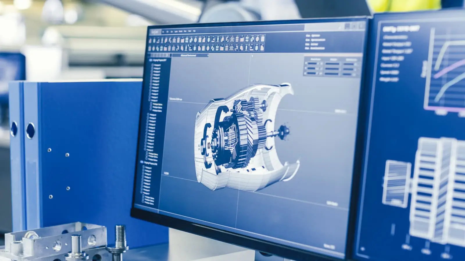
Gear Design Software: Gear design software can be used to optimize gear design and performance. The software can analyze gear geometry, tooth profile, material properties, and manufacturing tolerances to ensure proper gear function and performance.
Conclusion:
Gears are essential components in many mechanical systems and come in various types and configurations. The gear type and configuration should be selected based on the application requirements such as load, speed, noise, and efficiency. Proper gear design and manufacturing are critical for ensuring smooth and efficient gear operation.
Gear design software can be used to optimize gear design and performance, while gear alignment tools can be used to check gear teeth alignment. With proper gear design and manufacturing, gears can provide reliable and efficient power transmission in a wide range of applications.
For more information contact us at www.bccncmilling.com.
FAQS:
Here are some frequently asked questions on gears and sprockets:
What is the difference between a gear and a sprocket?
A gear is a cylindrical component with teeth on its circumference that meshes with another gear to transmit power and motion. A sprocket is a wheel with teeth that meshes with a chain to transmit power and motion.
What is a gear ratio?
A gear ratio is the ratio of the number of teeth on the driving gear to the number of teeth on the driven gear. It determines the speed and torque of the output shaft in relation to the input shaft.
What is a sprocket ratio?
A sprocket ratio is the ratio of the number of teeth on the driving sprocket to the number of teeth on the driven sprocket. It determines the speed and torque of the output shaft in relation to the input shaft.
How do you select the right gear or sprocket for an application?
The selection of the right gear or sprocket depends on several factors, such as the desired speed and torque, the application requirements, and the available space. It is important to consider these factors and consult a gear and sprocket expert to select the best option.
What are some common applications of gears and sprockets?
Gears and sprockets are used in various applications, including automotive transmissions, machine tools, robotics, bicycles, and conveyor systems. They are also used in industrial and manufacturing equipment to transmit power and motion between components.