1.0 What is plasma
When the gas is heated to roughly 2000 °C, the gaseous molecules break into atoms. Around 3000 °C is the temperature at which the atoms become ionized. Plasma describes this gaseous state.
In its early stages, plasma gas for machining was used to cut stainless steel, aluminum, and other nonferrous metals instead of using an oxy-flame. The process capacity was expanded with the developments to include metallic and non-conductive materials.
1.1 How Does a Plasma Cutter Work?
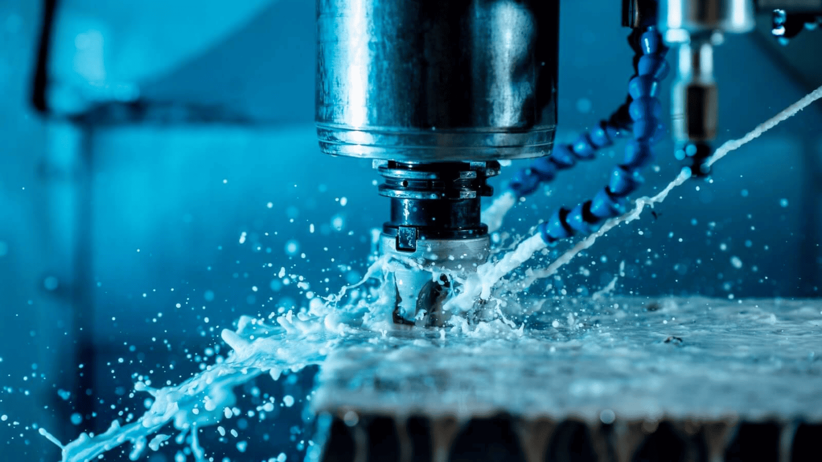
Thermal cutting is a technique used in the plasma cutting procedure. This indicates that it melts the metal rather than physically cutting it. The fundamental workings of the system never change. Compressed air or other gases, including nitrogen, are used in plasma cutters. These gases are ionized to produce plasma. Normally, when compressed gases come into contact with an electrode, they ionize to increase pressure. A stream of plasma is forced towards the direction of the cutting head as the pressure increases. A stream of plasma is produced by restricting the flow with the cutting point. This is then applied to the workpiece.
The workpiece is wired to the ground through the cutting table since plasma is electrically conductive. The metal melts as the plasma arc comes into touch with it because to the high temperature. The molten metal is also blown away simultaneously by the high-speed gases.

1.2 The Machining System
The Plasma Cutting method is based on the generation of a continuous arc between a water-cooled copper anode and a tungsten cathode. After being introduced at the cathode, gas flows through the anode. A high temperature plasma arc is produced when the temperature in the narrow area of the cathode reaches around 28,000 °C. Under the effect of such a high temperature, the substance melts and vaporizes quickly. The machining debris is subsequently washed away by an ionized gas stream. In compared to other traditional techniques such as turning, the material removal rate in the Plasma cutting process is significantly higher. Plasma cutting machining systems include the following components: plasma jet, plasma arc, air plasma, and shielded plasma.
Plasma Arc
The arc is created at the plasma torch's back electrode. The struck arc then advances to the conducting specimen. Temperatures of around 33,300 °C are generated. Damage to the electrode and the workpiece material occurs as a result of the double arcing effect that occurs between the workpiece and the nozzle. High heat transfer rates are achieved when heat is transferred from the anode to the workpiece.
Because of its higher efficiency, the Plasma Cutting technique is utilized for metal cnc machining services. The Plasma Cutting is not reliant on the chemical interaction that occurs between the work metal and the gas. The Plasma Cutting technique is also suited for any electrically conductive materials that cannot be processed using oxy-fuel gas cutting.

Plasma Jet
The plasma torch emits plasma, an ionized gas. The temperature of the jet is extremely high, at about 1600 °C. The jet that is released is called a plasma jet. The anode of the torch is cooled using cooling water. Water doesn't successfully participate in the material removal process since it absorbs a lot of heat from the anodic plasma torch. Non-conductive materials can be machined using the plasma jet technology even if they are challenging to do so. Oxy-fuel gas cutting cannot be used to mill electrically conductive materials.
Air Plasma
The Plasma Cutting method uses compressed air as the machining gas. Under the effect of the plasma arc's high temperature, the air disintegrates into its component parts.
Due to oxygen's ability to react with ferrous materials, the machining speeds are increased. The primary problem with plasma cutting is that the surface oxidizes heavily.
Hafnium zirconium or hafnium copper are utilized as substitutes for tungsten as an electrode material. Electrically conductive materials like copper, stainless steel, and aluminum might be machined using the air plasma.
Shielded Plasma
Here, water takes the role of the shield gas. Water forms a radial jacket all around the plasma burner. The cooling impact provided by water reduces the cut quality and cutting zone breadth. The reducing rates, however, remain unchanged. Gas-shielded plasma: When cutting various materials, helping gases are necessary in order to produce cuts of the appropriate quality. An outer shield gas, such nitrogen or argon, is supplied around the nozzle to shield the helping gases from the environment. Depending on the material being machined, a certain shielding gas will be employed. When cutting aluminum, stainless steel, or other non-ferrous metals, hydrogen is frequently employed. For mild steel, you can use air or oxygen.
Material Removal Rate
The workpiece surface's absorption of thermal energy from the plasma jet is what causes the removal of material. The plasma torch blows away the melted and vaporized metal. The material of the workpiece being machined will determine how machinable the procedure is. Additionally, the type of shield and machining gases employed in the process affects the pace at which maximum temperature is transferred, which in turn affects how machinable the process is. The speed of machining diminishes as metal thickness increases. To remove the molten metal from the machining zone, a greater gas flow rate is necessary together with an increase in power.
2.0 Tips for Better Results with Plasma Cutting
When selecting and utilizing a plasma cutter, performance might be improved if you take a few recommendations and best practices into account.
I. Select the appropriate plasma cutter
When selecting a plasma cutter, important parameters to keep in mind are output power, cutting speed and duty cycle. Consider the jobs you undertake most frequently while selecting your computer.
II. Prior to cutting, trace the route.
Without pressing the trigger, follow the route you wish to cut. To ensure you have sufficient movement freedom to create a continuous cut while making long cuts, rehearse your motions before pressing the trigger. Inconsistencies in the cut edge are frequently the consequence of stopping and beginning in the same spot, which is challenging. The material you will be working with can also be used to cut a design. In this manner, you may be certain that your cruising speed and settings are perfect.
III. Examine the consumables
The quality of the cut will be compromised if the tip or electrode is worn out or broken. So be sure to frequently check your consumables. Throw away the tip hole if it's crooked or has splash marks on it. Discard the electrode tip if it develops a pit. Consumables deteriorate with every cut, but conditions like moisture in the air supply, cutting materials that are too thick, or outdated technology speed up this process. For the greatest possible cut quality, it is advised to switch the tip and electrode at the same time. The consumable holder shouldn't be tightened too much. To generate an arc, the internal components must actually move. Therefore, just tighten the cup with your finger.
IV. Observe the moving speed
With metal in particular, cutting more quickly will result in a cleaner cut. Setting the machine to maximum power and varying your operating speed can help you cut through thicker material. Reduce the amperage while working with thinner material and switch to a tip with a lower amperage to produce a narrow kerf. The arc should exit the material at a 15-to-20-degree angle that is perpendicular to the direction of travel if the travel speed is appropriate. It indicates you are travelling too slowly if it drops straight down. You are going too quickly if it sprays back at you. A very clean cut with minimal debris on the cut's underside and little to no deformation of the metal may be achieved by moving at the proper speed and applying the proper amount of heat.

3.0 Applications of Plasma Cutting
Plasma cutters can be either manually operated or mechanically operated. To cut through particular types of metal, manual cutters are generally hand-held. These tools make welding work more convenient because they are often portable, adaptable, and on the smaller side. They generate a lot of cutting amperage, although they're usually employed to trim extra material in light-metal applications.
When combined with cutting tables, mechanical plasma cutters are often substantially bigger than manual plasma cutters. Punching, laser, or robot cutting systems may all be connected with mechanized plasma cutters. The table and portal that are employed determine the size of a mechanized plasma cutter. Since these systems are difficult to maneuver, the layout of the system as well as all of its components should be taken into account before installation. CNC Machining and Manufacturing services also provide combo systems that may be used for both welding and plasma cutting.

4.0 Advantages and Disadvantages of Plasma Cutting
Advantages
The portability of plasma cutting is excellent. The cutter itself may be made so small that it can be used as a portable instrument and is simple to move between job locations. The operation of a plasma cutting torch is also quite simple for brand-new personnel to master. Consequently, the plasma machine cutters have the following benefits to offer.
- A precision beam may draw curves, unusual forms, and several intersecting incisions. Plasma torches may be controlled manually or with the help of a computer to be directed as accurately as you would draw a line with a pencil.
- Additionally, plasma cutters provide rapid and effective cuts. Making a clean split in a piece of working metal using plasma takes just a quarter of the time of other comparable processes. Rapid processing periods reduce the chance of deformation, incorrect cuts, or metal abrasion.
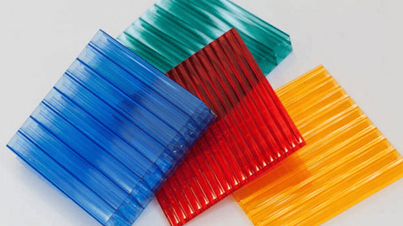
- Plasma cutting is adaptable and works with a variety of materials. With a ratio of 1:2 compared to oxygen cutting, plasma cutting is also more economical and energy-efficient.
- Furthermore, plasma equipment is thought to offer superior value for the money. Plasma torches need little upkeep and almost ever need to be replaced.
- Inert gases are also used in plasma cutting, which makes it considerably safer to use than cutting that uses oxygen. When used or stored, oxygen fuel poses a serious danger of explosion or unintentional ignite. On the other hand, when the torch is really in action, plasma cutting gas is merely transformed into a superheated plasma jet.
- High accuracy and reproducibility may be achieved using CNC machines.
- There are no chemical difficulties or upkeep requirements for the procedure.
- Since the procedure is thought to be clean, there is no longer any need for solvent wiping, ultrasonic cleaning, or grit blasting.
- There is no longer any chance of being exposed to dangerous substances.
Disadvantages
Unfortunately, there are a few disadvantages to plasma cutting.
- For thicker or denser metals, the majority of plasma cutters are ineffective. Plasma can only go down to a depth of around one inch due to its transient nature. You might have to resort to standard industrial sawing or metal milling service if you need to cut through enormous steel pillars or blocks.
- Although plasma cutting reduces ambient heat, it is loud and produces too many pollutants. Ensure that all plasma cutting occurs in a workshop that is well-ventilated and open.
- During the cutting process, plasma is also known for producing extremely brilliant flashes. Make sure you provide safety instructions and appropriate eye protection to any employee who works near or uses the plasma cutter.
- Despite being less expensive per cut than Oxy-fuel, plasma cutting can still be very expensive. If the equipment malfunctions, finding and replacing electrodes may be costly. Additionally, you might need to pay for a professional gas supply. Making the necessary plasma mix may be exceedingly challenging without specialized equipment on hand.
- Heat from the procedure damages and deteriorates the workpiece's surface.
- For extremely thick plates of mild steel, large power is needed.