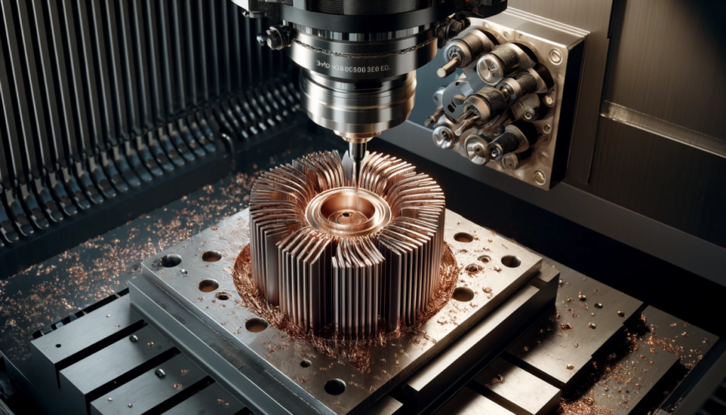
Heat sinks are a critical component in modern electronic and power systems. From high-density PCBs and LED assemblies to EV power modules, telecom infrastructure, and industrial drives, thermal management directly affects performance, reliability, and product lifespan. As power densities continue to increase, effective heat dissipation is no longer optional. It is a core design requirement. Among the available manufacturing methods, CNC milling remains one of the most versatile processes for producing custom aluminum and copper heat sinks, especially in low to medium production volumes or complex geometries.
Design for Manufacturability plays a central role in ensuring these parts perform as intended while remaining cost-effective and practical to produce. A well-designed heat sink not only meets thermal targets but also reduces machining time, material waste, inspection complexity, and lead time.
Material Selection: Aluminum vs. Copper in CNC Milled Heat Sinks
Material choice is the first major design decision in any CNC-milled heat sink project. It affects thermal performance, machining strategy, cost, weight, and long-term reliability. While both aluminum and copper are widely used in thermal management, they behave very differently in production. Selecting the right material requires balancing conductivity with manufacturability and budget constraints.
Thermal Performance Comparison
From a purely thermal perspective, copper outperforms aluminum.
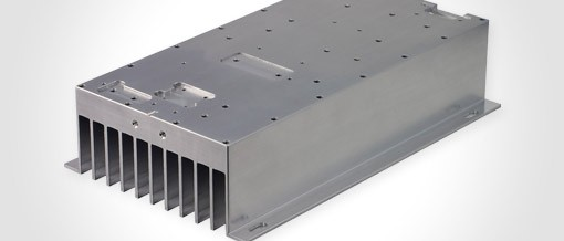
- Aluminum alloys such as 6061 and 6063 offer thermal conductivity in the range of 150 to 200 W per meter Kelvin. This is sufficient for most LED assemblies, telecom enclosures, power supplies, and general industrial electronics.
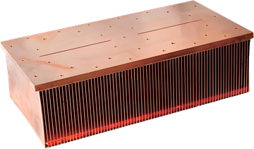
- Copper C110 provides conductivity around 390 to 400 W per meter Kelvin, nearly double that of aluminum. This makes it highly effective in high heat flux zones where rapid heat spreading is critical.
However, conductivity is only one part of the equation. Copper is significantly heavier than aluminum. In applications such as EV battery systems or pole-mounted telecom units, added weight increases structural requirements and transportation costs. Aluminum offers a strong balance between thermal efficiency and lightweight design.
In practice, aluminum is often used for the overall heat sink structure, while copper is strategically placed only where heat concentration is highest. For example, an IGBT module may use a copper insert beneath the semiconductor die to improve heat spreading, while the surrounding fin structure remains aluminum to reduce weight and cost.
Machinability and Manufacturing Impact
Manufacturing behavior differs substantially between these materials.
- Aluminum machines cleanly and efficiently. It allows higher spindle speeds, faster feed rates, and longer tool life. Surface finish is easier to control, and burr formation is typically minimal.
- Copper behaves as a gummy material. It requires lower cutting speeds, generates more heat during machining, and increases tool wear. Burr formation is more common, particularly along thin fins and edges.
These differences directly affect cycle time and production consistency. A heat sink that takes 20 minutes to machine in aluminum may require significantly longer in copper due to conservative cutting parameters and additional deburring operations.
For complex fin geometries, aluminum offers more predictable results. Thin or tall fins in copper are more susceptible to deformation during machining, especially if workholding is not optimized.
Cost Considerations
Material cost and machining time together determine the final part price. Copper typically costs several times more per kilogram than aluminum. When combined with slower machining speeds and higher tool wear, the overall manufacturing cost increases substantially.
Aluminum heat sinks are generally more economical for medium to large surface area designs. Copper becomes justifiable when thermal density is high, and performance margins are tight. In high-power laser drivers or compact inverter modules, where temperature rise must be minimized within a limited space, copper can provide measurable performance gains that offset its cost.
Consider two practical examples:
- An LED housing with deep vertical fins for passive cooling is well-suited to 6063 aluminum. The material supports good thermal performance while allowing efficient milling of multiple fins.
- A high-power IGBT baseplate operating under concentrated heat load may use a copper insert directly under the chip area. The rest of the structure remains aluminum to control weight and cost.
The most efficient designs often combine materials strategically rather than defaulting to full copper construction. Early DFM evaluation at the design stage prevents overengineering and keeps the solution aligned with both performance and manufacturing realities.
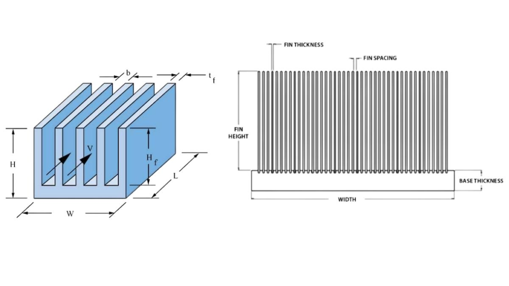
Fin Geometry Design for CNC Milling
Fin geometry has the greatest influence on both thermal performance and machining cost. While simulation tools often push designs toward thinner and taller fins for maximum surface area, those geometries are not always practical for CNC milling. A design that looks optimal in software can quickly become unstable, slow to machine, or prone to scrap on the shop floor.
DFM Guide for CNC-Machined Aluminum Heat Sinks
A well-balanced fin design maintains airflow efficiency while respecting tool limitations, vibration control, and structural integrity.
Fin Thickness and Spacing
The minimum fin thickness should be defined with the cutting tool in mind. CNC milling relies on end mills, and their diameter directly determines the minimum spacing that can be produced reliably.
- For aluminum heat sinks, a practical minimum fin thickness is around 1.0 mm, assuming moderate fin height.
- For copper, 1.2 mm or more is safer due to its softer, more ductile nature and higher burr formation.
- Fin spacing should be equal to or greater than the cutter diameter to avoid excessive tool deflection and rubbing.
Designs adapted from extrusion profiles often specify ultra-thin fins below 0.8 mm. While extrusion can support such dimensions in high-volume production, CNC milling cannot achieve them economically. Attempting to machine extremely thin fins leads to chatter, poor surface finish, and frequent tool breakage.
For example, a prototype LED heat sink originally designed with 0.7 mm fins required repeated rework due to bending during machining. Increasing the fin thickness to 1.5 mm stabilized production while maintaining sufficient airflow.
Fin Height and Aspect Ratio
Tall fins increase surface area but also increase machining risk. As the aspect ratio rises, vibration and tool deflection become more pronounced. This affects dimensional accuracy and surface finish.
From a practical standpoint:
- Depth-to-width ratios beyond 8:1 become increasingly difficult to machine consistently.
- Fin heights above 25 to 30 mm in aluminum require careful tool selection and stable fixturing.
- Copper fins of similar height are more susceptible to deformation due to material softness.
Thermally, there is also a point of diminishing returns. Airflow limitations may prevent effective heat removal from extremely tall fins. In forced-air systems, pressure drop must be considered. In passive systems, natural convection limits effective fin height.
A balanced design might reduce fin height slightly while increasing spacing to improve airflow. In many cases, this approach achieves similar thermal performance with lower machining risk and shorter cycle time.
Tool Access and Cutter Selection
Tool accessibility must be considered early in the design phase. CNC milling cannot produce perfectly sharp internal corners. All internal vertical corners will contain a radius equal to or greater than the cutter radius.
- If a 2 mm end mill is used, the internal corner radius will be at least 1 mm.
- Narrow channels deeper than four to five times the cutter diameter are difficult to machine cleanly.
- Extremely deep and narrow pockets increase tool wear and machining time significantly.
When internal corners are functionally critical, designers should either allow for radii or specify secondary operations, such as EDM, only if absolutely necessary.
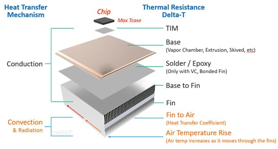
Base Thickness, Flatness, and Mounting Interface Design
The base of a CNC-milled heat sink serves two critical functions. It spreads heat from the source into the fin field, and it provides the mechanical interface to the electronic assembly. While fin geometry drives convection performance, base design determines thermal contact quality and structural stability during machining and operation.
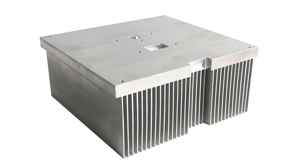
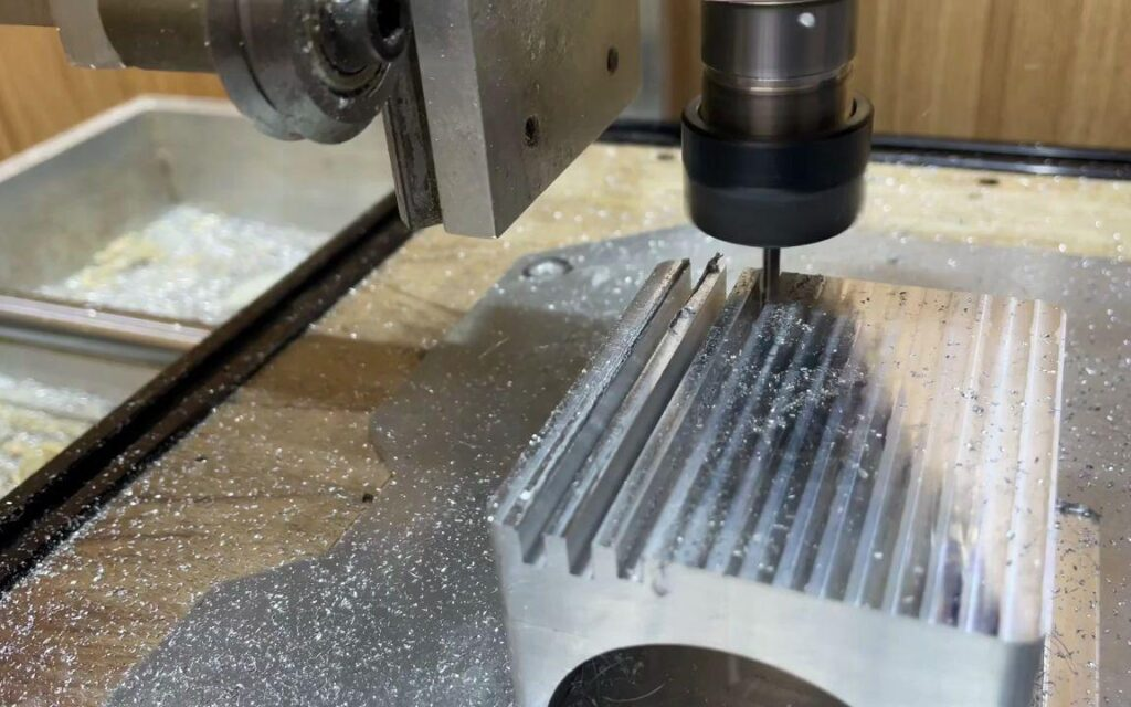
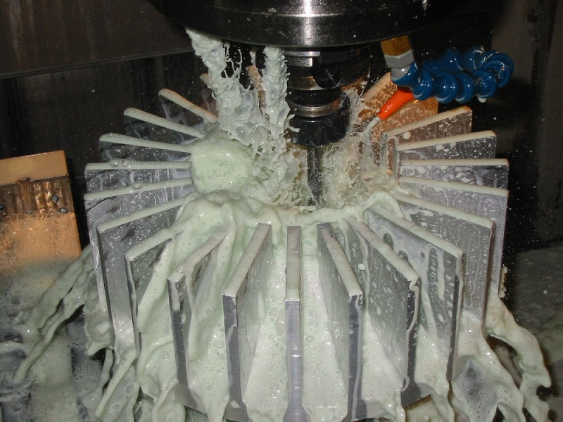
Custom CNC Milled Aluminum Heat Sink
A poorly designed base can warp during machining, compromise flatness, or introduce unnecessary weight and cost. Careful attention to thickness, flatness control, and mounting features ensures both thermal efficiency and manufacturability.
Base Thickness
Base thickness must balance rigidity, heat spreading, and material efficiency.
- If the base is too thin, it may deform during clamping and milling. This leads to residual stress and loss of flatness after release.
- If the base is excessively thick, material cost and machining time increase without proportional thermal benefit.
- For most medium-sized aluminum heat sinks, a base thickness between 5 mm and 12 mm provides adequate stiffness and heat distribution.
For example, in a 200 mm by 150 mm telecom heat sink, increasing the base from 6 mm to 8 mm reduced distortion during machining and improved flatness stability after anodizing. However, increasing it further to 12 mm showed minimal thermal improvement while adding unnecessary weight.
In copper designs, slightly thinner bases may still provide good heat spreading due to higher conductivity. Even so, mechanical stiffness must not be compromised.
Flatness Requirements
Thermal interface materials perform best when the mating surface is flat and uniform. Excessively tight flatness tolerances, however, increase machining and inspection costs.
A practical approach is to define flatness only where it matters.
- Specify tight flatness in the mounting region directly under the heat source.
- Allow standard machining tolerances outside the contact zone.
- Avoid applying global flatness requirements across the entire base unless functionally required.
For instance, a power electronics module may require a flatness of 0.05 mm across the contact pad area measuring 80 mm by 80 mm. There is rarely a need to extend that same tolerance to the full heat sink footprint.
Localizing critical tolerances reduces finishing passes and simplifies quality control while preserving thermal integrity.
Mounting Holes and Counterbores
Mounting features must be positioned with structural and machining constraints in mind. Holes placed too close to thin fins or edges weaken the structure and complicate machining.
Design guidelines that improve reliability:
- Maintain sufficient edge distance between threaded holes and fin structures.
- Avoid drilling into regions with thin cross sections that may deflect.
- Ensure thread engagement depth is appropriate for the material. In aluminum, a thread depth of 1.5 times the nominal screw diameter is often sufficient for standard loads.
As an example, consider a power electronics baseplate with an 8 mm thick aluminum base. The contact pad is machined locally to a finer surface finish, while M4 threaded holes are positioned outside the fin region. This configuration maintains structural integrity and simplifies fixturing during machining.
When counterbores or countersinks are required, designers should confirm that the remaining wall thickness supports the applied clamping force. Over-aggressive material removal around fasteners can create stress concentration and distortion over time.
By approaching base design as both a thermal and mechanical interface, engineers can achieve predictable assembly performance and reduce manufacturing variability.
Tolerances, Surface Finish, and Secondary Processes
Thermal performance alone does not define a successful heat sink. Dimensional control, surface condition, and protective treatments influence assembly quality, long-term reliability, and total manufacturing cost. Overly aggressive specifications can drive up machining time and inspection effort without delivering functional benefit. A disciplined DFM approach aligns tolerances and finishes with actual performance requirements.
Realistic CNC Tolerances
CNC milling is capable of tight precision, but not every feature requires it. Applying strict tolerances across an entire part increases setup time, slows machining, and complicates quality control.
In most heat sink applications:
- General dimensional tolerances of ±0.05 mm to ±0.1 mm are sufficient for non-critical features.
- Mounting hole locations may require tighter positional control when alignment with PCBs or modules is essential.
- Critical interface zones under power devices may justify stricter flatness or thickness limits.
For example, a telecom enclosure heat sink may function perfectly with ±0.1 mm tolerance on fin spacing and outer dimensions, while maintaining ±0.05 mm only in the mounting pad region. Specifying ±0.02 mm across the entire component would significantly increase cost without measurable performance improvement.
Clear differentiation between critical and non-critical features keeps inspection practical and production efficient.
Surface Finish Requirements
Surface finish influences thermal interface performance, corrosion resistance, and cosmetic appearance. However, mirror-level finishes are rarely necessary for functional thermal contact.
For mounting surfaces:
- A roughness value of Ra 1.6 to 3.2 micrometers is typical for good thermal interface material bonding.
- Finer finishes increase machining time and offer diminishing thermal benefit unless specified for a special interface such as direct metal bonding.
For fins and external surfaces, standard machined finishes are generally acceptable unless aesthetics are important for exposed consumer products.
In one industrial inverter project, the initial design specified a highly polished base surface. Testing showed no measurable thermal improvement compared to a standard Ra 1.6 micrometer finish. Relaxing the requirement reduced machining time and simplified inspection.
Surface finish should support function rather than aesthetics unless appearance is a defined requirement.
Post Machining Treatments
Secondary processes enhance durability and environmental resistance. The selected treatment must align with the base material and operating conditions.
For aluminum heat sinks:
- Clear anodizing improves corrosion resistance without significantly affecting dimensions.
- Black anodizing increases surface emissivity, which can enhance radiative heat transfer in passive cooling systems.
For copper components:
- Nickel plating protects against oxidation and maintains surface conductivity.
- In cold plate designs, plating also improves compatibility with thermal interface materials.
As an example, a telecom outdoor heat sink manufactured from 6063 aluminum benefits from black anodizing. The coating protects against weather exposure and improves radiation performance in natural convection environments.
Similarly, a copper cold plate used in a high-power converter may be nickel-plated to prevent surface oxidation during storage and operation.
Selecting appropriate surface treatment at the design stage avoids later modifications and ensures predictable long-term performance.
Machining Strategy and Cost Drivers in CNC Heat Sinks
Even when geometry and material are well selected, the manufacturing strategy ultimately determines cost and lead time. CNC-milled heat sinks are often produced in low to medium volumes, where machining efficiency has a direct impact on pricing. Understanding what drives cycle time allows designers to make small adjustments that significantly reduce production cost.
Design decisions made early in development frequently influence machining complexity more than expected.
Cycle Time Drivers
Cycle time is largely controlled by geometry and material behavior.
Several factors have a measurable effect:
- Fin count and fin depth
A higher number of deep fins increases tool passes and extends machining time. Each additional fin requires repeated slotting operations. Reducing fin density slightly can shorten cycle time without significantly affecting thermal performance.
- Material type
Aluminum supports higher spindle speeds and feed rates. Copper requires slower cutting parameters and more frequent tool changes. The same geometry in copper may take substantially longer to machine.
- Tool changes and setups
Designs requiring multiple tool diameters increase non-cutting time. Similarly, parts that require flipping for machining on multiple sides increase setup effort and alignment checks.
For example, a large aluminum heat sink with 40 fins may require nearly double the machining time compared to a similar design with 25 well-spaced fins. Thermal simulation often shows only marginal performance loss, while manufacturing savings are significant.
Design Simplification Techniques
Simplification does not mean compromising function. It means eliminating unnecessary complexity.
Effective approaches include:
- Reducing excessive fin density when airflow is limited by system constraints. In forced air systems, fan capacity often limits performance more than fin count. Optimizing spacing can improve airflow and reduce pressure drop.
- Standardizing hole sizes and thread types. Using consistent fastener dimensions reduces tool changes and simplifies assembly.
- Avoiding complex undercut pockets beneath fins. Deep pocketing increases machining time and complicates workholding. In many cases, a slightly thicker base provides similar heat spreading performance with simpler machining.
A practical case involved a power supply heat sink initially designed with intricate base pocketing to reduce weight. After reviewing structural and thermal requirements, the design was simplified to a uniform base thickness. The final part was easier to machine and showed a negligible thermal difference.
When to Consider Hybrid Designs
Hybrid construction can offer performance benefits while controlling cost.
One common approach combines:
- An aluminum body for a lightweight structure and efficient fin machining.
- A copper slug or insert is positioned directly beneath the primary heat source to enhance local heat spreading.
This configuration reduces total copper volume while maintaining thermal efficiency where it matters most.
For higher production volumes, alternative manufacturing methods may also become viable. Skived fins or extruded profiles can provide thinner fins at a lower cost per unit when quantities justify tooling investment.
A clear example illustrates the benefit. An original design specified a fully machined copper heat sink for a compact inverter module. After review, the design was revised to use an aluminum body with a copper insert beneath the semiconductor package. The result was a significant reduction in material cost and machining time while meeting thermal targets.
Strategic decisions at the DFM stage ensure that performance objectives are achieved without unnecessary manufacturing expense.
Conclusion
CNC milling provides flexibility and precision for thermal management components, particularly in applications that demand custom geometry or moderate production volumes. When properly designed, aluminum heat sinks deliver an effective balance of thermal performance, weight control, and manufacturing efficiency. Copper remains a valuable option for high heat flux regions where enhanced conductivity justifies its cost and machining complexity.
Strong DFM practices reduce unnecessary cost, improve dimensional stability, and shorten production lead time. By aligning material selection, fin geometry, tolerances, and machining strategy with real manufacturing capabilities, engineers can achieve both thermal reliability and economic efficiency. Close collaboration between design and manufacturing teams remains essential to delivering heat sinks that perform consistently in demanding electronic and power systems.