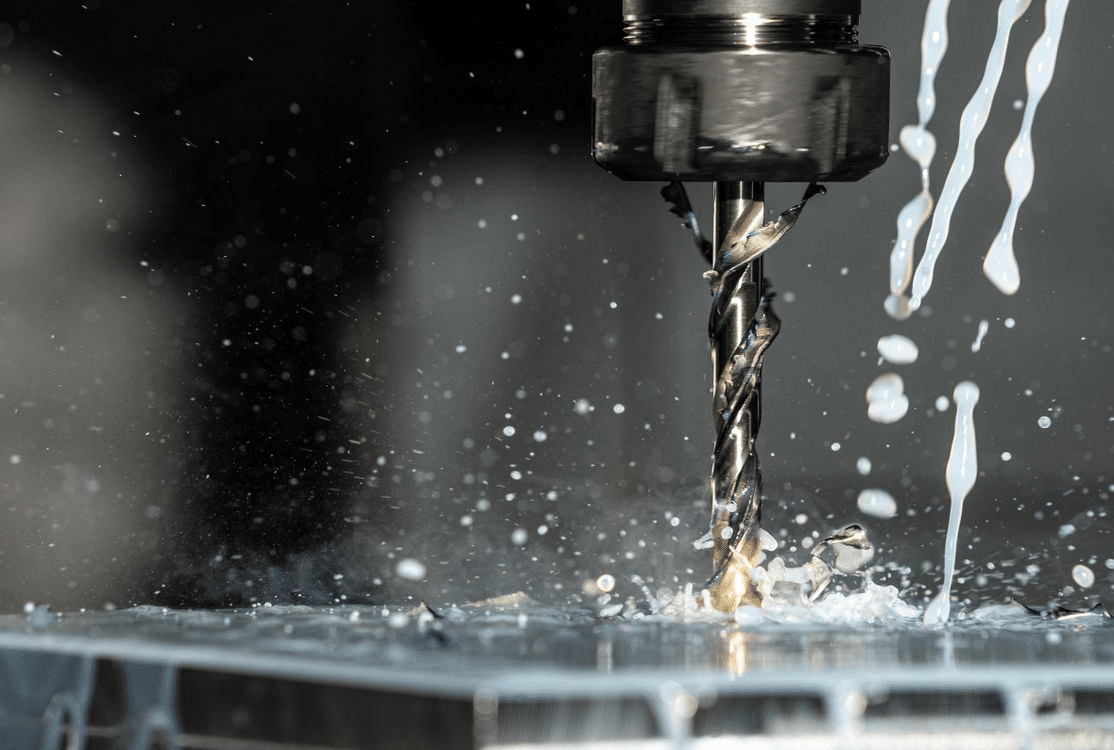
Threaded features are among the most critical elements in CNC-machined components. They enable structural assembly, load transfer, sealing, alignment, and serviceability across nearly every mechanical system. Whether the part is a precision instrument housing or a heavy structural bracket, the reliability of the threaded connection often determines the reliability of the entire assembly.
Threading For CNC Machined Parts
Poorly designed threads can compromise strength, increase production cost, and create unnecessary complications during machining or installation. Common failures in threaded parts include stripping, misalignment, and galling. While these issues may appear during assembly, they are usually rooted in design decisions made much earlier.
Thread Fundamentals for CNC Machining
Before discussing strength or failure modes, it is important to understand how thread geometry and standards affect machining and cost. Thread selection is not only a mechanical decision. It directly influences tool wear, cycle time, inspection effort, and overall production stability.
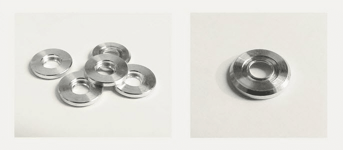
Internal vs. External Threads
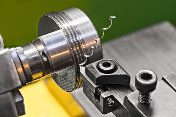
Threads can be cut on the outside of a part or inside a hole. External threads are typically easier to machine and inspect because tools have better access, and chip evacuation is more predictable. Internal threads, especially in blind holes, require greater attention to tool selection, depth control, and chip management.
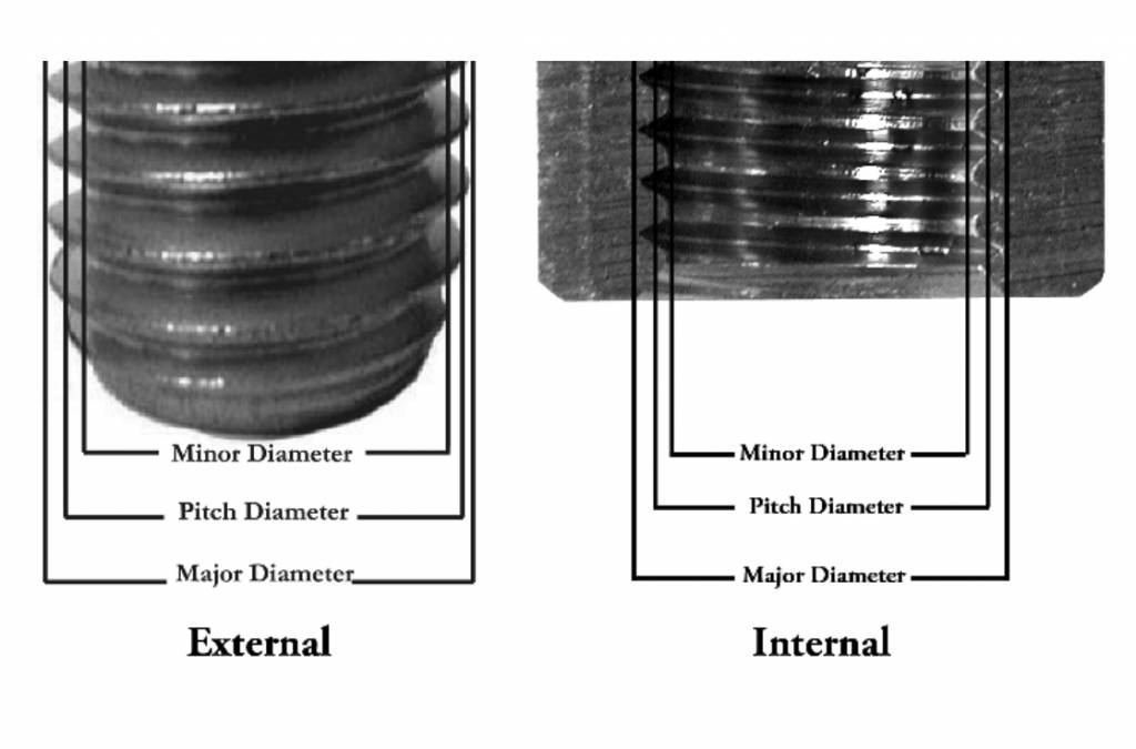
Internal vs. External Threads in CNC Machining
For example, tapping a deep blind hole in stainless steel often increases tool breakage risk. In contrast, cutting an external thread on the same material is usually more stable and easier to control.
Common Thread Standards
Most CNC-machined parts use one of the following standards:
- Unified threads (UNC and UNF)
Common in North America. UNC threads have a larger pitch and are suited for general fastening. UNF threads provide finer pitch and greater tensile strength in the same diameter.
- Metric ISO threads
Widely used internationally. Designations such as M8 × 1.25 indicate nominal diameter and pitch.
Consistency within a product line reduces tooling changes and simplifies assembly. Mixing standards in the same assembly increases both inspection time and the risk of cross-threading.
Thread Geometry and Fit
Key geometric elements include major diameter, minor diameter, and pitch. These define load-carrying capacity and how tightly components fit together.
Thread classes such as 2A and 2B provide standard fits for most applications. Class 3 fits are tighter and intended for precision assemblies, but they increase machining time and inspection requirements.
In many production environments, specifying a tighter class than necessary adds cost without a measurable performance benefit.
Coarse vs. Fine Threads
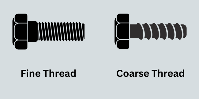
Thread pitch selection affects both strength and manufacturability.
- Coarse threads
Better for softer materials such as aluminum and plastics. They resist stripping and assemble faster. They are also more tolerant of dirt and minor damage.
- Fine threads
Provide greater tensile strength and better resistance to vibration loosening. They are common in high-strength steel applications.
However, fine threads are more prone to galling in stainless steel assemblies and require cleaner manufacturing conditions.
Through Holes vs. Blind Holes
Through holes are easier to machine because chips can evacuate freely. Blind holes require additional drill depth and bottom clearance to prevent tool damage.
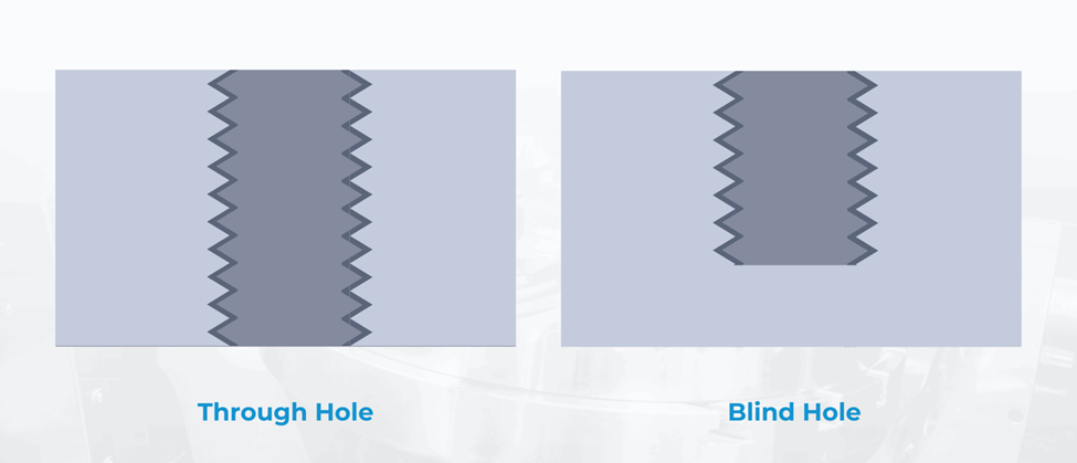
A common design mistake is specifying full thread depth to the bottom of a blind hole. This leaves no space for tap runout and increases scrap rates. Allowing proper bottom clearance improves consistency.
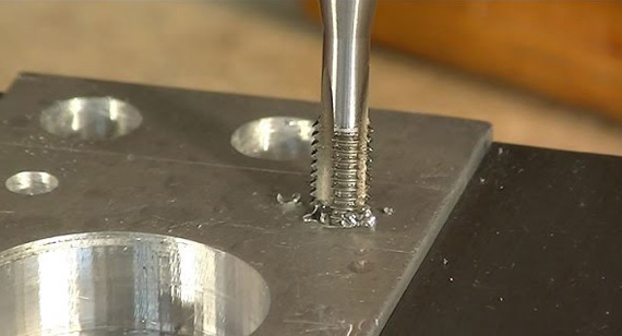
Tapping vs. Thread Milling
Tapping is fast and cost-effective for standard sizes and high-volume production. Thread milling offers better control in harder materials and allows adjustment of thread fit without changing tools.
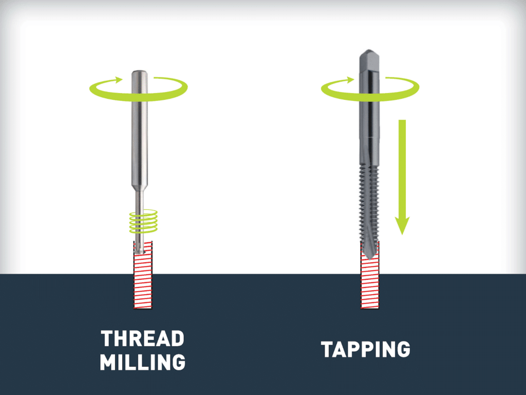
Thread milling is particularly useful in stainless steel or titanium, where tap breakage can halt production. Although slightly slower, it reduces scrap risk in critical components.
Design Insight:
Thread choice directly affects machinability and cost. Coarse threads in aluminum machines quickly and reduce tool wear. Fine threads in hardened steel require slower speeds and increase inspection demands. Selecting standard sizes, reasonable fit classes, and manufacturable hole types improves both part quality and production efficiency.
Designing Threads for Strength and Load
Once the thread form and standard are selected, the next step is ensuring the connection can carry the required load. Many thread failures are not caused by poor machining but by insufficient engagement length, weak surrounding material, or poor geometric support. Designing for strength means understanding how load transfers through the engaged threads and into the parent material.
Determining Thread Engagement Length
Thread engagement length directly affects shear strength. However, adding more thread depth does not indefinitely increase capacity. After a certain point, the fastener will fail in tension before the internal threads shear.
As a practical reference:
- Steel components typically require engagement equal to one nominal diameter. An M10 bolt in steel generally performs well with about 10 mm of engagement.
- Aluminum components often require 1.5 times the nominal diameter to achieve comparable strength.
- Plastics may require two times the diameter or more, depending on material grade and load conditions.
For example, a 1/4 inch bolt threaded only 4 mm into aluminum will often strip under moderate torque. Increasing engagement to 9 or 10 mm dramatically improves reliability without changing bolt size.
Shear Area and Tensile Failure
Thread failure usually occurs in one of two ways. The bolt fractures in tension, or the internal threads shear off. The weaker element fails first.
If the internal material is softer than the bolt, stripping becomes more likely. This is common when high-strength steel fasteners are used in aluminum housings. Proper engagement depth and sometimes the addition of thread inserts are required to balance the load path.
Avoiding Excessive Thread Depth
Over-threading is a frequent design oversight. Designers sometimes specify full thread depth through thick bosses under the assumption that more threads equal more strength. In practice, once optimal engagement is reached, additional depth adds machining time but no structural benefit.
For example, specifying 25 mm of thread engagement for an M8 fastener in steel rarely increases load capacity beyond what 8 mm to 10 mm already provides. The bolt will fail before the threads do.
Wall Thickness and Edge Distance
Threaded holes require adequate surrounding material. Insufficient wall thickness leads to cracking or distortion under load.
Good practice suggests:
- Wall thickness around a threaded hole should be at least 0.5 times the nominal diameter for moderate loads.
- The minimum edge distance from the hole center to a free boundary should generally exceed one diameter.
Placing a threaded hole too close to an edge weakens the component and increases the chance of breakout during tapping or assembly.
Thread Relief and Runout
In blind holes, thread relief at the bottom prevents incomplete threads and reduces stress concentration. Without adequate runout space, the tap compresses material at the bottom, creating inconsistent thread quality.
A typical example is a blind M6 hole drilled only to the exact thread depth. The tap cannot fully form usable threads at the bottom, reducing actual engagement and lowering strength. Providing extra drill depth ensures full thread formation.
Designing threads for strength is not about maximizing dimensions. It is about matching engagement length, material properties, and geometric support to the actual load. When these elements are balanced, the connection performs predictably and avoids premature failure.
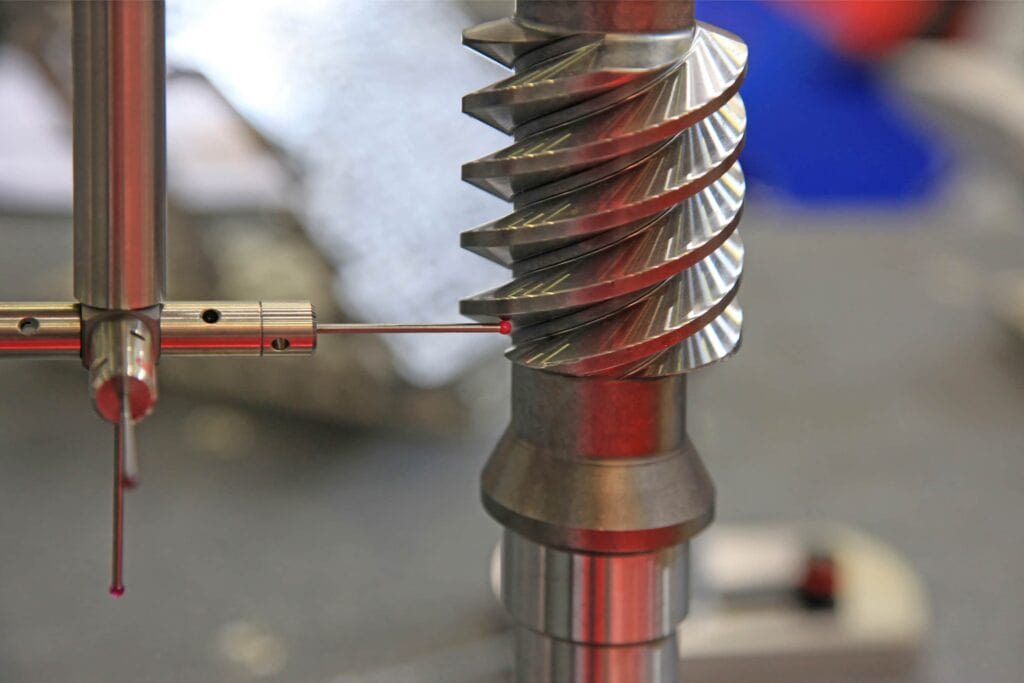
Thread Tolerances, Fits, and Manufacturability
Thread strength alone does not guarantee performance. Fit, tolerance selection, and machining method determine whether the part can be produced consistently and assembled without difficulty. Many production delays originate from drawings that specify tighter tolerances than the application truly requires.
Thread Classes and Fit Selection
Unified threads are commonly specified as 2A or 2B for general use. Class 3A or 3B provides a tighter fit for precision assemblies. While tighter classes reduce looseness, they also increase machining time and inspection effort.
In practice, specifying class 3 threads for a standard enclosure fastener often adds cost without improving function. Class 2 fits are sufficient for most structural and mechanical assemblies. Reserving tighter classes for alignment of critical components keeps production efficient.
Metric threads follow similar principles. Selecting standard tolerance grades rather than custom fits simplifies manufacturing and avoids unnecessary inspection complexity.
Cost Impact of Overly Tight Tolerances
Tight fits reduce clearance between mating threads. This increases the chance of binding, especially after coating or plating. It also requires slower machining speeds and more frequent tool replacement.
For example, a stainless steel component with a tight internal tolerance may pass inspection before anodizing. After coating, the threads can become difficult to assemble because the surface thickness reduces effective clearance. The result is rework or scrapped parts.
Choosing practical tolerance ranges reduces these risks and maintains predictable assembly behavior.
Coating and Surface Treatment Considerations
Surface treatments alter thread dimensions. Designers should account for coating thickness when specifying internal threads.
Consider the following:
- Anodizing increases surface thickness on aluminum, effectively reducing internal thread diameter.
- Zinc plating on steel adds measurable buildup that affects fine threads more than coarse threads.
- Powder coating can significantly alter fit if threads are not masked.
Failing to account for coating thickness often leads to assembly interference. A simple adjustment in thread class or masking specification prevents this issue.
Surface Finish and Thread Performance
Surface roughness influences friction during assembly. Rough internal threads increase torque and elevate galling risk in stainless or titanium components.
Specifying a reasonable surface finish on tapped holes, especially in hard materials, improves consistency. Thread milling often produces smoother finishes compared to tapping in certain alloys.
Designing Blind Holes Properly
Blind threaded holes require additional geometric consideration. Without adequate depth and chamfering, assembly problems are common.
Key design practices:
- Drill deeper than the required thread engagement to allow tap runout.
- Provide a small chamfer at the hole entrance to guide the fastener.
- Leave bottom clearance so the fastener does not bottom out before clamping.
A frequent production issue occurs when a bolt appears fully tightened but is actually bottoming against the hole base. The joint feels secure yet lacks proper clamping force.
When to Choose Thread Milling
Thread milling provides flexibility in adjusting the minor diameter and fit. It is especially beneficial for larger threads, hard materials, and high-value components where tap breakage would be costly.
For example, in aerospace stainless housings, thread milling reduces scrap risk compared to tapping. Although cycle time is slightly longer, overall production reliability improves.
Design Tip
Threads should be designed with the machinist in mind. Standard classes, practical tolerances, adequate blind hole depth, and consideration of coatings lead to repeatable production. A thread that is simple to machine is also easier to inspect and assemble, which ultimately reduces total manufacturing cost.
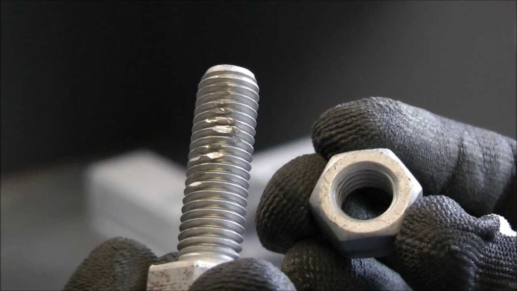
Understanding Galling in Threaded Parts
Even when threads are strong and properly machined, another failure mode can compromise the assembly. Galling is one of the most frustrating and costly problems in threaded connections, particularly in CNC-machined metal parts. It often appears suddenly during installation and can permanently damage both components.
What Galling Is
Galling is a form of adhesive wear. Under pressure and friction, microscopic high points on mating threads weld together. As rotation continues, these junctions tear apart, transferring material from one surface to the other. The result is rough, damaged threads that may seize completely.
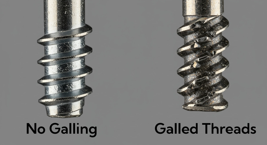
In practice, galling is often first noticed when a bolt suddenly becomes difficult to turn. Within seconds, the fastener can lock in place. Attempting removal usually destroys both the internal and external threads.
Why It Occurs in CNC-Machined Parts
CNC-machined components frequently have clean, smooth metal surfaces with minimal oxide layers. While this improves dimensional accuracy, it can increase metal-to-metal contact during assembly.
Several factors increase the likelihood of galling:
- Tight thread fits
Reduced clearance raises contact pressure between mating surfaces. Fine tolerance stainless threads are particularly vulnerable.
- High friction during installation
Rapid tightening with power tools generates heat and surface adhesion.
- Lack of lubrication
Dry assembly significantly increases metal contact and friction.
- Similar material pairing
A stainless bolt into a stainless housing is a common example. Identical materials have similar hardness and surface chemistry, which promotes adhesion.
Materials Most Prone to Galling
Certain materials are especially susceptible due to their surface characteristics and ductility.
- Stainless steel
Austenitic grades such as 304 and 316 are widely used but highly prone to galling when paired together. - Aluminum
Soft aluminum threads can smear under load, particularly with fine-pitch fasteners. - Titanium
Titanium threads can seize rapidly without lubrication due to strong adhesive tendencies.
For example, assembling a 316 stainless bolt into a 316 stainless blind hole without lubricant often leads to seizure before full torque is reached. This is a frequent issue in marine and food processing equipment.
Real World Failure Scenarios
Galling often results in:
- Seized fasteners that must be drilled out.
- Torn internal threads requiring rework or insertion of thread inserts.
- Damaged external threads on high-cost fasteners.
In production settings, a single galled fastener can scrap an otherwise finished component. In field applications, it can cause extended downtime.
Understanding galling is essential because it is not random. It is a predictable outcome of material pairing, surface condition, and assembly practice. Proper design decisions can significantly reduce its occurrence.
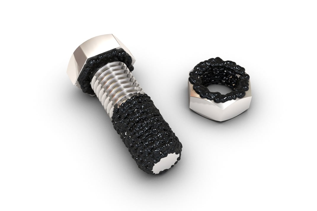
Design Strategies to Prevent Galling
Because galling is predictable, it can be engineered out of most assemblies. Preventing it requires attention to material pairing, thread fit, surface treatment, and assembly control. The goal is to reduce friction, lower contact stress, and avoid similar metal interfaces under high pressure.
Material Pairing
One of the most effective strategies is to avoid mating identical gall-prone materials.
Consider practical combinations:
- Stainless bolt with bronze or brass insert
The softer insert reduces adhesive interaction and protects the primary component.
- Stainless bolt with carbon steel insert
Differing hardness levels lower the risk of material transfer.
- Aluminum housing with steel thread insert
This improves both wear resistance and load capacity.
In marine applications, stainless bolts threaded directly into stainless housings frequently seize. Replacing the internal threads with a bronze insert eliminates recurring failures.
Use of Thread Inserts
Thread inserts, such as Helicoils or solid key locking inserts, provide hardened internal threads and reduce friction between mating components. They are especially valuable in aluminum and magnesium parts where thread stripping and galling can occur together.
Although inserts add cost at the component level, they often reduce warranty claims and field repairs. In aerospace and automotive applications, inserts are routinely specified in critical joints for this reason.
Adjusting Thread Class and Clearance
Tight fits increase friction and contact pressure. In gall-prone materials, selecting a standard or slightly looser class can improve assembly reliability without sacrificing structural performance.
For example, switching from a tight class 3 internal thread to a standard class 2 in stainless components often reduces seizure incidents during production.
Fine pitch threads should also be used carefully in stainless steel or titanium. Coarser threads reduce surface contact and lower friction.
Surface Treatments and Coatings
Surface modification creates a barrier between mating metals and reduces adhesion.
Effective approaches include:
- Anodizing aluminum components
This hardens the surface and reduces direct metal contact.
- Plating fasteners with zinc or nickel
The coating acts as a sacrificial layer and improves lubricity.
- Dry film lubricants
Common in aerospace assemblies, these coatings reduce friction without attracting debris.
In titanium assemblies, applying a dry film lubricant before installation significantly reduces seizure risk.
Lubrication During Assembly
Even with optimal design, assembly practice matters. Applying anti-seize compound or light lubrication dramatically lowers friction.
Lubrication When Reusing Fasteners
Specifying lubrication in assembly documentation prevents technicians from installing fasteners dry. Clear torque specifications should accompany lubrication requirements because lubrication reduces friction and alters torque-to-tension relationships.
Torque Control
Excessive torque increases contact pressure and friction. Defining appropriate torque limits protects both threads and fasteners.
For instance, stainless fasteners installed with impact tools often exceed recommended torque values. Manual torque control or calibrated drivers reduce variability and galling incidents.
Eliminating Threads When Appropriate
In some cases, redesigning the joint removes the risk entirely. Alternatives include:
- Through bolts with nuts instead of tapped holes.
- Studs are installed once and left in place to avoid repeated metal contact.
- Captive nuts or threaded inserts molded into components.
When repeated assembly and disassembly are expected, relying solely on tapped stainless threads is rarely ideal.
Engineering Insight
Preventing galling is a balance of strength, manufacturability, and long-term reliability. Proper material pairing, practical tolerances, surface treatment, and controlled assembly create predictable performance. Designing with these factors in mind avoids seized fasteners, damaged components, and costly rework in both production and field service.
Conclusion
Thread design directly influences structural performance, manufacturability, and long-term reliability. Most failures in threaded CNC components can be traced to avoidable design oversights such as insufficient engagement, improper tolerances, poor material pairing, or lack of assembly control. Galling, in particular, is not an unpredictable defect but a foreseeable result of friction, tight fits, and similar material interfaces.
By selecting appropriate thread standards, engagement depths, and tolerance classes, and by accounting for coatings and material compatibility, designers can significantly reduce failure risk. Early collaboration with CNC machinists further improves outcomes by aligning design intent with real production constraints. Well-engineered threaded features not only improve assembly efficiency but also extend product lifespan and reduce costly rework.