Runout in CNC machining refers to the deviation of a rotating component from its true centerline during rotation. In practical terms, it means the spindle, toolholder, or cutting tool does not rotate perfectly true, even though it may appear properly mounted. This deviation is often measured in microns, yet it directly affects how accurately a tool cuts material and how consistently a machine performs.
Even very small amounts of runout matter. A few microns can change cutting forces, degrade surface finish, shorten tool life, and introduce dimensional errors. This article focuses on the most common sources of runout in CNC environments, including spindle condition, toolholder quality, taper cleanliness, and inspection practices, and explains how these factors influence machining quality and long-term productivity.
Understanding Runout in CNC Machining
Runout occurs when a rotating component does not follow a perfectly centered rotational path. In CNC machining, this usually involves the spindle, toolholder, or cutting tool rotating slightly off-center. The machine may still function, but the cutting edge no longer engages the material evenly. Over time, this small deviation shows up as inconsistent cuts, visible tool marks, or unexplained tool wear.
Runout develops from a combination of mechanical tolerances, wear, and setup conditions. No rotating system is perfectly ideal, but CNC machining demands tight control because tools often operate at high speeds and close tolerances. As spindle speed increases, even minimal deviation becomes more influential on cutting behavior.
Types of Runouts
Understanding the different forms of runout helps identify where problems originate and how they affect machining results.
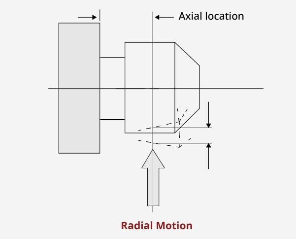
- Radial runout
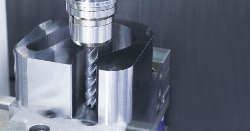
Radial runout refers to side-to-side deviation from the true centerline during rotation. This is the most common and most damaging type in milling and drilling. For example, if an end mill has radial runout, one flute removes more material than the others, leading to uneven wear and reduced tool life.
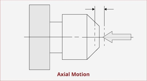
- Axial runout
Axial runout is movement along the axis of rotation. It affects face milling, boring, and operations where flatness and perpendicularity are critical. Excess axial runout can cause poor surface finish on faced parts and inconsistent depth of cut.
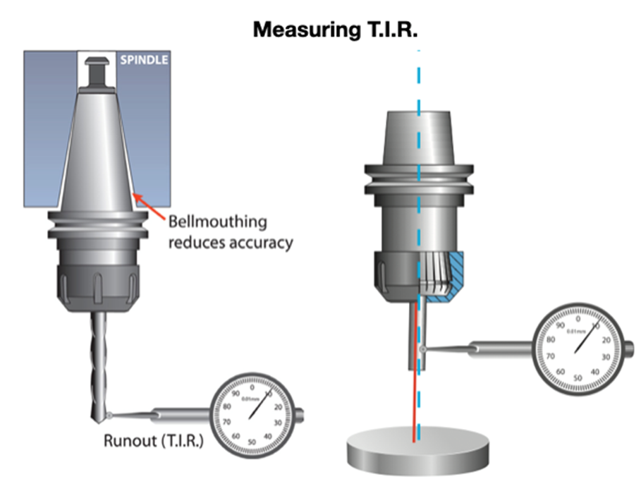
- Total Indicated Runout (TIR)
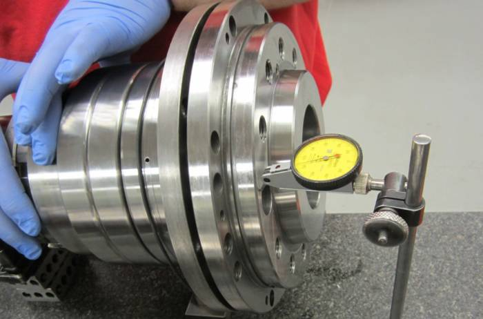
TIR represents the combined effect of radial and axial deviation measured at a specific point. It is the value most commonly referenced in CNC inspection because it reflects the actual behavior of the rotating system as a whole. TIR is typically measured using a dial indicator while slowly rotating the spindle or tool.
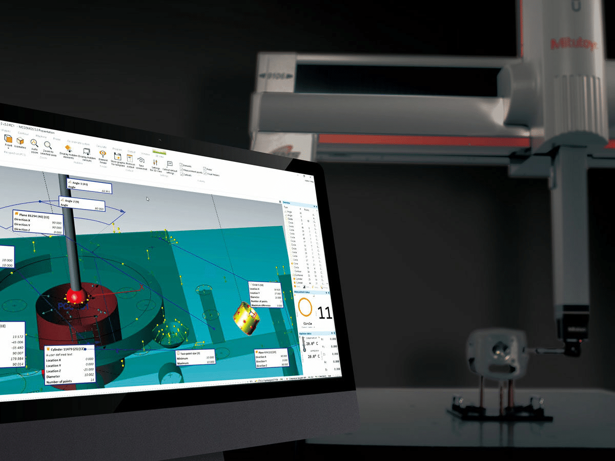
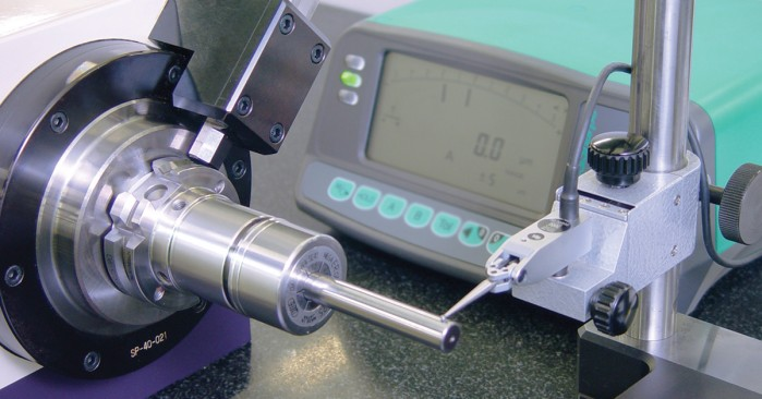
Measuring Total Indicated Runout
Typical Acceptable Runout Ranges
Acceptable runout depends on the operation and machine capability, but general production guidelines are well established.
- High-precision finishing operations often require TIR below 5 microns
- General milling and drilling may tolerate 10 to 15 microns
- Roughing operations can function at higher values, though tool wear increases noticeably
For example, a drilling operation producing tight-tolerance holes will show size variation quickly if runout exceeds acceptable limits, even if the drill itself is new.
Machine Runout vs Tool System Runout
It is important to distinguish between machine-related runout and tool system runout. Machine runout originates from the spindle, bearings, or alignment. Tool system runout comes from toolholders, collets, pull studs, or improper clamping.
A spindle may measure within specification at the nose, yet excessive runout can still appear at the cutting edge due to a worn collet or poor taper contact. This distinction matters because replacing tools alone will not correct a spindle issue, and servicing the spindle will not fix poor toolholding practices.
Understanding where runout originates is the first step toward controlling it. Measurement without interpretation often leads to unnecessary adjustments, while targeted inspection leads to reliable improvement.
Primary Causes of Runout
Runout rarely comes from a single fault. In most CNC environments, it develops through a combination of spindle condition, tooling quality, and everyday handling practices. Each source may contribute only a few microns, but together they can push the system beyond acceptable limits. Understanding these causes helps identify whether the issue is mechanical, procedural, or both.
Spindle Related Factors
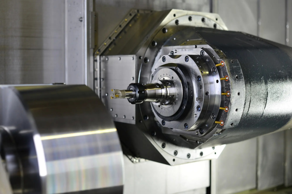
The spindle is the foundation of rotational accuracy. Any degradation here affects every tool used on the machine.
- Bearing wear: Spindle bearings gradually wear due to load, speed, and heat. As clearance increases, the spindle shaft no longer rotates concentrically. This often appears first at higher RPMs, where vibration and tool noise become noticeable before dimensional issues are detected.
- Thermal growth: Heat causes spindle components to expand. During long production runs, temperature changes can alter bearing preload and shaft alignment. For example, a machine that measures acceptable runout during a cold start may drift outside tolerance after several hours of continuous cutting.
- Spindle alignment issues: Improper installation or past crash events can cause slight misalignment between the spindle axis and machine structure. Even minor misalignment introduces consistent runout that cannot be corrected through tooling changes alone.
Toolholder and Tooling Issues
Tooling-related problems are among the most common and easiest to overlook causes of runout.
- Toolholder quality: Low-quality or worn toolholders often lack consistent internal geometry. Over time, repeated clamping and release can distort critical contact surfaces, leading to measurable runout at the tool tip.
- Worn or damaged collets: Collets lose elasticity and roundness with use. A collet that appears visually intact may still clamp unevenly, especially on small-diameter tools. This is a frequent cause of excessive runout in high-speed milling applications.
- Improper tool clamping: Incorrect tightening torque or uneven tool insertion can tilt the tool slightly within the holder. For example, tightening a collet nut without proper torque control can introduce runout even when all components are new.
Taper Cleanliness and Contact Problems
The spindle taper and toolholder interface is a critical but often neglected area.
Dirt, chips, oil residue, or fretting corrosion on tapers prevent full contact. Even a thin film of contamination can shift the toolholder off-center. Poor taper contact reduces rigidity and increases runout under load.
Pull stud condition also plays a role. Worn or incorrect pull studs may not seat the toolholder consistently, leading to variation each time the tool is loaded.
Accumulation of Small Errors
Runout often results from error stacking. A spindle with minor bearing wear, combined with a slightly worn collet and imperfect taper cleanliness, can produce significant total runout. Individually, each issue may appear acceptable. Together, they create measurable and repeatable quality problems.
Recognizing how these factors interact is essential before attempting correction. Addressing only one component rarely solves runout issues when multiple contributors are present.
Measuring and Inspecting Runout
Measuring runout correctly is essential for diagnosing machining problems and maintaining process stability. Without consistent inspection methods, runout issues are often misattributed to tooling or programming errors. Reliable measurement allows machinists and engineers to identify whether the source lies in the spindle, the toolholder, or the cutting tool itself.
Accurate inspection also requires repeatability. Measurements should be taken under controlled conditions, using clean components and consistent procedures, to avoid misleading results.
Common Inspection Tools
Several tools are commonly used in CNC shops to evaluate runout, each suited to specific inspection points.
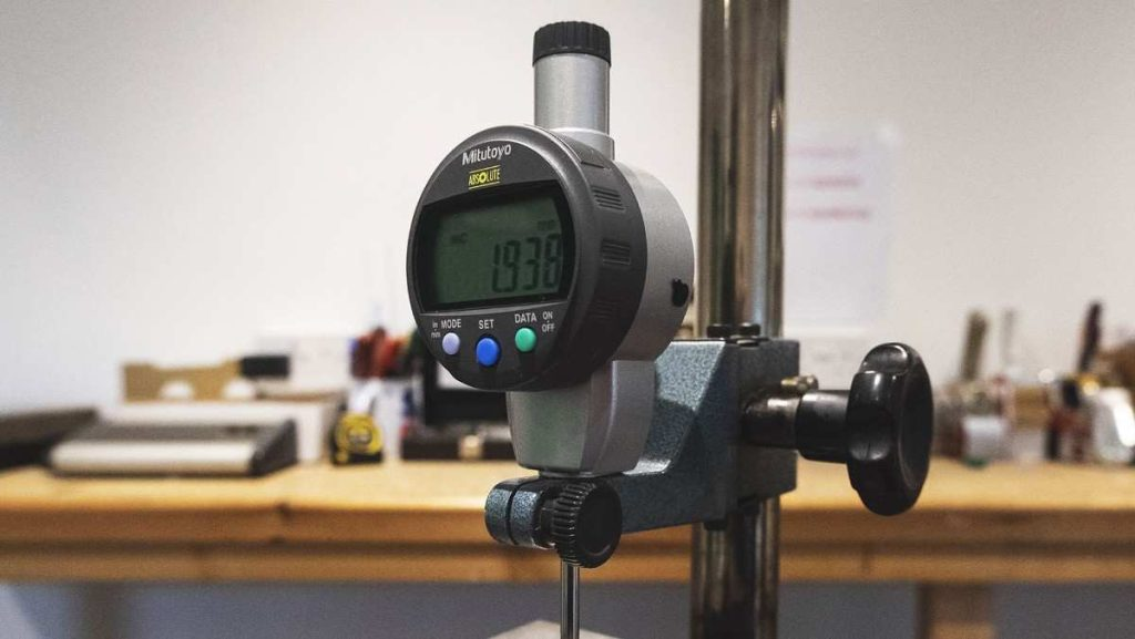
- Dial indicators: Dial indicators are widely used due to their simplicity and precision. When mounted on a magnetic base, they allow direct measurement of radial or axial deviation by rotating the spindle slowly by hand. Indicators with one micron resolution are typically preferred for precision work.
- Test bars: Test bars provide a known straight reference for evaluating spindle condition. By indicating along the length of a test bar, it becomes easier to distinguish spindle runout from toolholder-related errors. For example, increasing deviation further from the spindle nose often indicates bearing or alignment issues.
- Runout gauges: Dedicated runout gauges are designed for quick checks at the toolholder or cutting tool. They are commonly used in production environments where frequent inspection is required without extended setup time.
Where to Measure Runout
Measurement location directly influences the interpretation of results. Checking only one point often leads to incorrect conclusions.
- Spindle nose to evaluate machine condition independent of tooling
- Toolholder taper to verify contact quality and seating consistency
- Tool shank or cutting edge to assess the actual cutting condition
For instance, low runout at the spindle nose combined with high runout at the tool tip usually indicates a tooling or clamping issue rather than a spindle problem.
Step-by-Step Inspection Best Practices
Begin by cleaning all contact surfaces, including the spindle taper, the toolholder, and the pull stud. Mount the indicator securely and apply light, consistent contact pressure. Rotate the spindle slowly by hand and record the maximum and minimum readings to determine TIR.
Measurements should be repeated to confirm consistency. If values change between checks, seating or contamination issues are likely present.
Recommended Inspection Frequency
Inspection frequency depends on production demands and quality requirements. High-precision environments often check runout daily or at each tool change. General production shops may perform checks weekly or after tooling incidents such as crashes or abnormal tool wear.
Regular inspection reduces guesswork and prevents small issues from becoming costly quality problems. Consistent measurement practices also create a baseline that helps track machine health over time.
Quality Impact: How Microns Affect Machining Results
Small amounts of runout have a direct and measurable impact on machining quality. While a few microns may seem insignificant, they alter how cutting forces are distributed across the tool. This imbalance affects surface finish, dimensional accuracy, and overall process reliability. In precision machining, these effects appear quickly and consistently.

Micron-Level Machining Accuracy
Understanding this impact helps explain why runout control is not only a maintenance concern but also a quality requirement.
Effect on Surface Finish
Runout causes uneven engagement between the cutting edges and the workpiece. In milling, one flute may carry most of the cutting load while others barely engage. This produces visible tool marks, inconsistent finishes, and variation from part to part. In finishing operations, even a minimal runout can prevent achieving the required surface roughness values.
For example, a face milling operation may meet dimensional tolerances but still fail visual inspection due to chatter marks caused by uneven cutter engagement.
Uneven Tool Loading and Premature Tool Wear
When a single cutting edge absorbs most of the load, it wears faster than the others. This shortens tool life and increases the risk of sudden failure. In drilling operations, excessive runout often leads to rapid margin wear and poor chip evacuation, even when feeds and speeds are correctly set.
Over time, this uneven wear pattern makes tool performance unpredictable and increases tooling costs.
Vibration, Chatter, and Dimensional Errors
Runout contributes to vibration by creating fluctuating cutting forces. This instability can lead to chatter, especially at higher spindle speeds or with long tool overhangs. Chatter not only damages surface finish but also causes dimensional variation and accelerates machine wear.
In tight-tolerance work, these variations may push parts outside specification even though the program and offsets remain unchanged.
Impact on Holes and Tool Breakage
Hole quality is particularly sensitive to runout. Excessive runout leads to poor roundness, oversize holes, and tapered bores. In small-diameter drills, even slight deviation increases bending stress, raising the likelihood of tool breakage.
For example, a carbide drill operating with elevated runout may fail prematurely despite conservative cutting parameters.
Cost Implications
The cumulative cost of runout is often underestimated. Scrap parts, rework, increased inspection time, and reduced tool life all add to production expense. Over extended runs, these costs outweigh the time and effort required to measure and control runout.
Recognizing how microns influence machining results reinforces the need for consistent monitoring and corrective action before quality issues escalate.
Runout Control and Prevention Strategies
Controlling runout requires a preventive approach rather than reactive correction. Once excessive runout appears at the cutting edge, quality and tool life are already compromised. Effective control focuses on maintaining consistency across the spindle, toolholding system, and daily handling practices.
Runout in Machining and How to Avoid It
A disciplined approach to prevention reduces variability and improves long-term machine performance.
Toolholder Selection and Maintenance
Toolholders play a critical role in maintaining concentricity. High-quality holders with accurate internal geometry provide more consistent results, especially in finishing and high-speed applications. Over time, toolholders should be inspected for wear, fretting, or deformation at contact surfaces.
For example, replacing worn collets on a scheduled basis often restores acceptable runout without further adjustments.
Proper Taper Cleaning and Handling
Clean tapers ensure full contact between the spindle and toolholder. Before tool installation, both tapers should be wiped clean and inspected visually. Compressed air should be used cautiously, as it can drive debris deeper into the spindle.
Proper handling also matters. Dropping toolholders or placing them on dirty surfaces introduces damage that may not be immediately visible but contributes to runout during operation.
Correct Tool Clamping and Torque Practices
Consistent clamping force is essential for repeatable tool positioning. Using torque wrenches or preset tightening systems helps avoid uneven tool seating. Over-tightening can distort collets, while under-tightening allows micro-movement during cutting.
In production environments, standardizing clamping procedures reduces operator-dependent variation.
Spindle Health Monitoring and Preventive Maintenance
Regular spindle inspection helps detect early signs of bearing wear or thermal issues. Tracking runout values over time provides insight into gradual degradation. When trends show a consistent increase, planned maintenance can be scheduled before quality issues appear.
For example, documenting runout measurements monthly often reveals changes long before vibration or noise becomes noticeable.
Practical Runout Limits by Operation Type
Not all operations require the same level of runout control. Roughing operations can tolerate higher values, while finishing and precision drilling demand tighter limits. Defining acceptable runout thresholds based on operation type helps balance productivity and quality.
By aligning prevention strategies with actual machining requirements, shops can maintain control without unnecessary downtime.
Diagnosing Runout Problems in Production Environments
When runout becomes a recurring issue, a structured diagnosis prevents unnecessary adjustments and wasted time. Random changes to tooling or offsets often mask the real cause without resolving it. A clear diagnostic sequence helps isolate the source and apply the correct fix.
Separating Spindle Issues from Tooling Issues
Start by measuring runout at the spindle nose using a clean test bar. If readings are within acceptable limits at this point, the spindle is likely not the primary issue. Attention should then shift to the toolholder, collet, and clamping method.
If elevated runout appears directly at the spindle nose, tooling changes will not correct the problem. In such cases, further spindle inspection or service evaluation is required.
Comparing Static and In-Cut Behavior
Static measurements do not always reflect cutting conditions. A tool may indicate acceptable runout at rest but behave differently under load. Monitoring tool wear patterns and surface finish during machining provides additional clues.
For example, consistent wear on a single flute often confirms effective runout even if static measurements appear marginal. This observation supports corrective action without relying solely on indicator readings.
Using Tool Changes as a Diagnostic Tool
Swapping components one at a time helps isolate the source. Changing only the tool, then only the collet, and finally the toolholder allows patterns to emerge. If runout follows a specific holder across machines, the issue is clearly tooling-related.
This approach is especially useful in multi-machine shops where identical programs produce different results.
Establishing Baselines and Documentation
Recording acceptable runout values for each machine creates a reference point for future checks. When values drift, corrective action can be taken early. Documentation also supports maintenance planning and justifies tooling replacement based on data rather than assumptions.
A disciplined diagnostic process turns runout control from a reactive task into a predictable part of quality management.
Conclusion
Runout directly influences machining accuracy, surface quality, and tool life, even when deviations are measured in only a few microns. Left unchecked, it introduces variability that affects part consistency, increases wear, and drives up production costs. Understanding where runout originates and how it behaves in real cutting conditions allows machinists and engineers to address problems at the source rather than reacting to symptoms.
Long-term control depends on prevention and discipline. Clean interfaces, reliable toolholding practices, regular inspection, and documented baselines protect machine health and process stability. When runout is managed deliberately, CNC systems deliver predictable results, higher quality output, and sustained productivity over time.