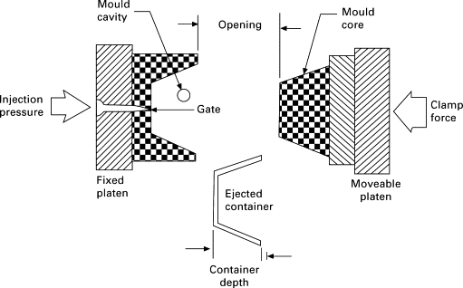
One of the most popular manufacturing techniques for large-scale production of premium plastic components is injection molding. Its capacity to produce accurate, consistent results makes it important throughout industries, from consumer electronics and automobile parts to medical devices and industrial equipment. However, careful design is crucial to achieve the best possible performance, longevity, and cost-effectiveness in molded parts. Defects, longer cycle times, and higher production costs can result from even small mistakes like incorrect wall thickness, insufficient draft angles, or poorly positioned gates.
Thus, this blog discusses the fundamental design guidelines that engineers and product designers need to adhere to in order to produce injection-molded parts that are both aesthetically pleasing and manufacturable. Companies may avoid tooling modifications, cut down on total development time, and guarantee that their finished products meet the highest standards of reliability and quality by grasping these principles early in the design cycle.
1. Wall Thickness
The performance, cost, and manufacturability of injection-molded parts are all significantly influenced by wall thickness. The thickness of a part's walls affects everything from filling pressure to shrinkage rate since plastic materials respond differently during flow, packing, and cooling. In order to guarantee structural integrity, consistent dimensions, and effective production, it is important to choose and design the appropriate wall thickness.
Thickness on Injection Molded Parts
Depending on the material type and intended use, acceptable wall thickness ranges for the majority of injection-molded plastics usually range from 1.0 mm to 3.5 mm. Better dimensional stability, quicker cycle times, and reduced production costs are guaranteed when the right thickness is chosen at the design phase. Here, we will discuss some major types of wall thickness that are most important in injection molding design rules.
1. Nominal Wall Thickness
The primary or baseline thickness that is maintained across the majority of the component is known as the nominal wall thickness. It is chosen according to the material's properties, the necessary strength, and its moldability.
Benefits:
- guarantees steady cooling and flow,
- reduces flaws like warpage and sink marks.
- gives consistent shrinking
The nominal thickness of most thermoplastics is between 1.0 and 3.5 mm.
2. Uniform Wall Thickness
In injection molding, this is the recommended design method. Melted plastic fills the mold cavity uniformly and cools at a steady pace when the thickness is uniform.
Benefits:
- Diminished warpage
- Reduced sink markings
- Reduced cycle times
- Enhanced stability in dimensions
Although uniformity is seen as an extension of the nominal wall thickness, its significant influence on manufacturability makes it worth considering as a distinct type.
3. Non-Uniform Thickness
It is utilized only when necessary for assembly or functionality. Extra material may be needed in places like mounting bosses, snap fittings, and hinges.
Rule of design:
- Limit alterations to 10%–15% of the original
- Make gradual changes
- Steer clear of steps that trap heat.
Careful engineering is required for non-uniform walls to avoid internal strains and aesthetic flaws.
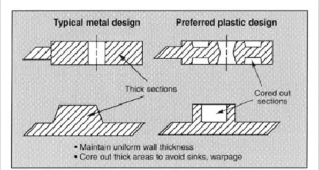
4. Thick Wall Selection
For structural strength, load-bearing parts, or threaded regions, thicker walls (beyond the above-specified ranges) could be necessary.
Risks:
- Sink stains
- Vacuous
- Overly long cooling periods
Using ribs in place of solid bulk or coring out the thick section are common alternatives.
5. Thin Wall Selection
In consumer goods, packaging, and electronics, thin-wall molding is used to minimize weight or improve performance.
Qualities:
- Usually, walls are < 0.5–1.0 mm.
- High-flow materials are needed.
- Requires high injection pressures and rates.
- Leads to reduced costs and quicker cycle times.
Gate position and flow length must be carefully taken into account in thin-wall designs.
6. Rib-Supported Wall Thickness
To increase stiffness without producing thick or heavy areas, designers use ribs rather than thickening the walls.
Benefits
- Enhancement of strength without material accumulation
- Improved cooling performance
- Preventing sink problems
- Ribs increase load-bearing capacity while preserving the nominal wall thickness.
2. Sharp Corners and Radii
Injection-molded parts' performance and manufacturability are significantly impacted by corner geometry. Although sharp internal or external corners may appear insignificant in the CAD model, they may significantly compromise structural integrity and present serious molding issues. Radii that are properly designed increase material flow, lessen stress concentration, and improve the final part's durability and beauty.
For these reasons, in plastic part engineering, avoiding sharp corners and using suitable radii is regarded as a key design criterion. Many of the problems caused by sharp corners are resolved by using appropriate corner radii, which also enhances the overall quality of the product.
- Enhanced Durability and Strength
Smoothly rounded edges reduce localized stress concentration and distribute tension uniformly. This greatly improves impact resistance and mechanical performance.
- Optimized Molten Plastic Flow
Smooth flow routes are encouraged by Optimized Flow of Molten Plastic Radii, which enable the material to fill the cavity uniformly and without hesitation or turbulence. As a result, there are fewer flow-related flaws and a more uniform surface quality.
- Consistent Wall Thickness.
Through preserving thickness continuity at transitions, adding radii lowers the possibility of shrinkage flaws and enhances dimensional stability.
- Increased Tool Life.
Mold longevity is increased, and maintenance expenses are decreased when tools with rounded corners endure less stress and wear.
Design Standards for Radii
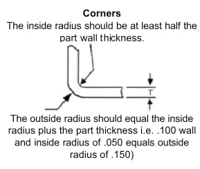
- In normal circumstances, internal radii ought to be at least 0.5–1.0 times the thickness of the wall.
- External radii, which are usually the sum of the internal radius and the wall thickness, should be greater than the interior radii.
- To prevent sudden changes in geometry, keep surface transitions smooth.
- Steer clear of making radii that are too big since they could distort the part's geometry or interfere with assembly tolerances.
These recommendations aid in ensuring that radii maintain functional precision while enhancing structural integrity.
4. Rib and Boss Design
In injection-molded parts, ribs and bosses are essential structural elements that are frequently employed to improve strength, support assemblies, offer mounting locations, and guarantee functional performance without increasing total wall thickness. When properly developed, these characteristics increase stiffness and load-bearing capacity while preserving economical material consumption and manufacturing feasibility.
However, flaws like sink marks, warpage, insufficient filling, or weak weld lines can result from poorly built ribs or bosses. Producing long-lasting, superior molded parts requires an understanding of their design concepts.
Rib Design
To improve bending stiffness and structural strength without increasing the main wall, ribs are thin, projecting features are added to plastic components. They enable designers to maintain the part's lightweight and mold-friendliness while achieving great mechanical performance.
The Use of Ribs
- Boost the rigidity and stiffness
- Cut down on part deformation when under stress
- Encourage large, level surfaces
- Boost structural stability without adding weight
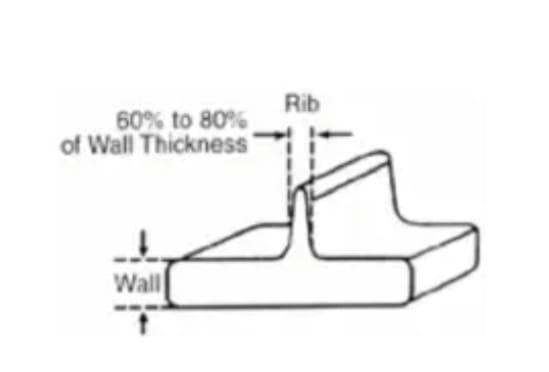
Essential Rib Design Guidelines
- Rib Thickness
The nominal wall thickness should be 40–60% of the rib base. Due to the slow cooling and material buildup, thicker ribs result in sink marks.
- Rib Height
Typically, it should be 2.5 to 3 times the wall's standard thickness. Taller ribs may result in weak, thin constructions or filling issues.
- Angle Draft
For simple ejection, ribs must have the right draft, which is usually 0.5° to 1° per side.
- Distance Between Ribs
To guarantee adequate flow and cooling, ribs should be separated by at least twice the thickness of the wall.
- Rib Tip Diameter
Strength is increased, and stress concentration is avoided by a small radius at the apex of the ribs.
Advantages of Properly Designed Ribs
- Decreased use of material
- Quicker cooling time
- higher ratio of stiffness to weight
- reduced flaws caused by shrinkage and warpage
Boss Design
Bosses are elevated, cylindrical features that can be utilized for alignment points, screws, inserts, or fasteners. They frequently occur in assemblies, housings, and enclosures that need to be mechanically fastened.
The Goal of Bosses
- Provide places to mount threaded inserts or screws.
- Support the joining of several molded pieces
- Keep everything aligned when assembling.
- Anchor structural elements
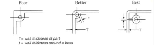
Essential Design Guidelines for Bosses
- Wall Thickness
At its base, the boss's outer diameter should preserve 60% of the nominal wall thickness. Steer clear of too-thick walls since they lead to sink marks and lengthy cooling times.
- Height of the Boss
To avoid instability, it should be just tall enough to engage the screw. Standard screw bosses adhere to torque and thread-depth specifications provided by the manufacturer.
- Radii and Fillets
To guarantee seamless transitions and lessen stress concentration, add fillets at the base of the boss.
- Bosses' Rib Reinforcement
To avoid bending or breaking, use ribs to support tall or load-bearing bosses. Ribs should adhere to rib design guidelines and connect to walls with appropriate transitions.
- Angle of Draft
To release mold, let a draft of 0.5° to 1° on each side.
Typical Problems with Bad Boss Design
- Top surfaces with sink markings
- Cracking while being assembled or under stress
- Filling narrow cylindrical features is difficult.
- Warpage as a result of heavy bulk buildup
5. Gating Design Rule
In injection molding, the gate is a crucial control point that allows molten plastic to enter the mold cavity. Material flow, cavity filling, cooling rates, weld line development, and mechanical qualities are all directly impacted by proper gate design, including its placement, kind, size, and quantity. Short shots, sink marks, flow reluctance, warpage, or weld line flaws are all consequences of poor gating design that impair both practical and aesthetic quality. So, there are some gating design rules to keep in mind during injection molding.
Gate Location
The location of the gate has a major impact on the plastic's cooling behavior and flow pattern. To guarantee consistent flow and reduce flow-induced stresses, gates should ideally be placed at the thickest areas or the center of mass. Long flow channels caused by improper placement can lead to non-uniform mechanical characteristics, uneven filling, and differential cooling.
Practical Factors to Remember:
- Gates should not be placed next to sharp edges or aesthetic surfaces.
- To avoid weld lines in high-stress regions, place gates for structural sections.
- To guarantee even filling, large or asymmetrical parts might need more than one gate.
Type and Geometry of Gates
Shear stress, flow patterns, and aesthetic results are all impacted by different gate types. Edge gates, pin gates, submarine (tunnel) gates, sprue gates, and fan gates are common varieties. Part geometry, wall thickness, aesthetics, and functional needs all play a role in selection.
Design Standards:
To prevent flow hesitation, keep the transition from the gate to the cavity seamless. To ensure proper ejection and avoid gate tearing, apply the required airflow angles (0.5°–1° per side).
Gate Dimensions and Quantity
The gate must let enough flow without creating undue pressure or shear stress. While undersized gates may result in high local pressures or partial filling, oversized gates increase material consumption and cooling time. Large or intricate parts can use several gates, but they must be positioned carefully to avoid weld lines.
Cooling:
The cooling system and gate placement are related. Gates should be positioned to enable balanced heat dissipation throughout the part in order to minimize warpage and sink marks.
Typical Flaws Caused by Inadequate Gating
- Short shots: partial filling brought on by a small gate or a flow constraint.
- Poor gate placement exacerbates weld lines, which are weak points where two flow fronts converge.
- Sink marks are caused by uneven packing, frequently in close proximity to dense areas or awkwardly positioned gates.
- Burn scars are the result of severe shear or trapped air close to the gate.
- Flow hesitation is a turbulent or interrupted flow caused by abrupt gate transitions or sharp bends.
6. Draft Angle Guidelines:
The draft angle is intended for tapering of an injection-molded part's vertical faces to make removal from the mold easier. Draft angles are an essential design concern because they limit part damage, avoid surface flaws, and reduce friction during ejection. An inadequate draft can cause molded parts to deform, adhere to the mold, or get scratches and stress marks, all of which lower manufacturing quality.
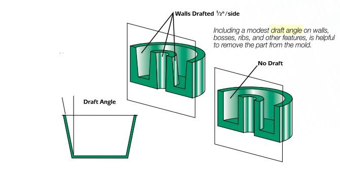
Recommended Draft Angles
The part geometry, the kind of plastic, and the texture of the wall determine the required draft angle. The following draft angles are suggested by industry recommendations and research studies.
| Feature/Surface of the Part | Suggested Angle of Draft |
| polished or smooth surfaces | 0.5° to 1 |
| Texture surfaces | 1° – 2° |
| Strong walls or deep ribs | 1° – 3° |
| Parts with thin walls | 0.5° to 1.5° |
| Cosmetic-critical surfaces | 1° – 2° (higher recommended for textured finishes) |
Draft Rules for Particular Features
- Ribs
To avoid sticking and guarantee smooth ejection, provide a 0.5°–1° draft to the rib walls. To lessen the concentration of stress, mix with fillets at the bases of the ribs.
- Bosses
A draft of 0.5°–1° is often sufficient. For stability, taller bosses could need more draft or rib reinforcement.
- Openings & Holes
Draft should be included in internal surfaces to prevent friction during core pull or pin ejection.
- Large Cavities
Draft angles may need to be increased to 2°–3° to facilitate removal from molds with high aspect ratios.
Best Procedures
- Even if the mold is well polished, always keep the draft to a minimum.
- For rough surfaces, increase the draft because friction is large.
- Use gentle transitions when combining features with varying draft requirements to avoid stress concentration.
- Prior to mold manufacture, validate draft angles using simulation tools to forecast ejection forces and possible flaws.
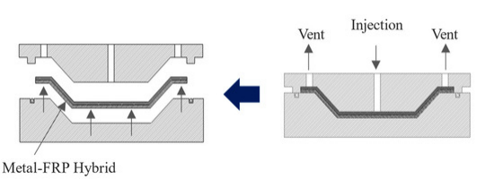
7. Venting and Cooling Considerations
In venting, the air inside the cavity is removed rapidly to avoid compression, overheating, or blockage of melt flow during injection. Usually, separating lines, ejector pins, or lifter mechanisms have tiny passages that allow for venting.
In research study, reducing pressure at the melt front and vent placement optimization enhances cavity filling and minimizes burn marks. Inadequate venting raises the temperature of trapped air, which degrades polymer chains and produces obvious burn flaws, according to experimental research.
Recommended Vent Dimensions
Research reveals typical vent depths of:
- For the majority of thermoplastics, 0.01–0.03 mm
- 0.03–0.05 mm for high-viscosity materials
- Vent land length: 3–6 mm
These values allow air escape without allowing molten plastic to flash.
2. Cooling
In injection molding, the cooling system takes up over 50–70% of the cycle time. Temperature gradients throughout the part are reduced, and consistent heat extraction is guaranteed by an effective cooling design. Reduce discrepancies in shrinkage and warpage by achieving uniform cooling. Prevent internal stress and uneven shrinking.
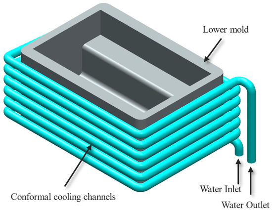
CAD illustrating a design of a conformal cooling channel utilized in injection molding.
Guidelines for Cooling Channel Design
- The ideal distance between cooling channels and the cavity surface is two to three times their diameter.
- More consistent temperature distribution is made possible by conformal cooling channels made possible by additive manufacturing.
- Use baffles and bubblers for deep and small core features when straight channels are impractical.
8. Design Rule Checklist
- Choose uniform wall thickness to reduce warpage and sinks.
- To reduce stress, use radii rather than abrupt corners.
- Use ribs and bosses for strength, but keep them slim.
- Provide enough draft angle for convenient part ejection.
- Gates should be kept positioned for minimal faults and smooth filling.
- Ensure proper venting to avoid air traps.
- Design cooling channels for even cooling.
- Avoid unneeded undercuts to simplify tooling.
- For molding, keep tolerances reasonable.
The Final Words:
Manufacturing Design for injection molding entails balancing part performance with manufacturing efficiency. Designers may drastically lower faults and production costs by adhering to important guidelines, such as keeping uniform walls, adding appropriate airflow, guaranteeing smooth flow through efficient gating, and providing sufficient cooling and venting.
Good design decisions made early in development contribute to better-quality products, shorter cycle times, and more dependable molding processes. Successful, economical plastic product manufacture starts with careful, mold-friendly design.