Oxyfuel Gas Welding (OFW) is a welding method that uses oxygen and a mixture of different fuels to produce a flame. The main distinction between these techniques is the kind of gas that is employed. OFW is also extensively employed in cutting torches to sever metal plates and other components.
The main processes within the OFW group are:
- Oxyacetylene Welding (OAW)
- Oxyhydrogen Welding (OHW)
- Pressure Gas Welding (PGW)
Of these, Oxyacetylene Welding (OAW) is the most important because of its wide variety of uses and adaptability. The procedures can be carried out using a filler metal or not, and with or without pressure.
In OFW, a flame produced at the welding torch's tip is used to melt the base metal and maybe add filler metal. Within a mixing chamber, usually a component of the torch assembly, fuel gas, and oxygen are combined in exact proportions. Melting metal from the plate edges unites with any filler metal (if any) in a common weld pool, which cools and solidifies.
Oxyacetylene Welding (OAW)
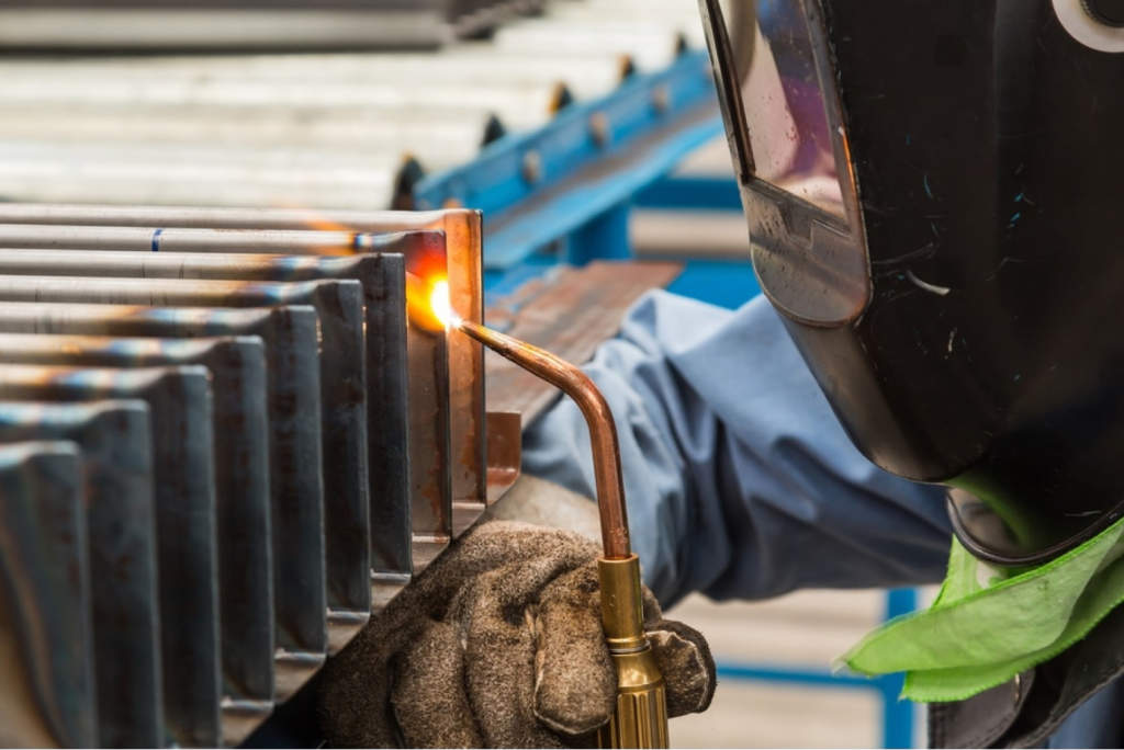
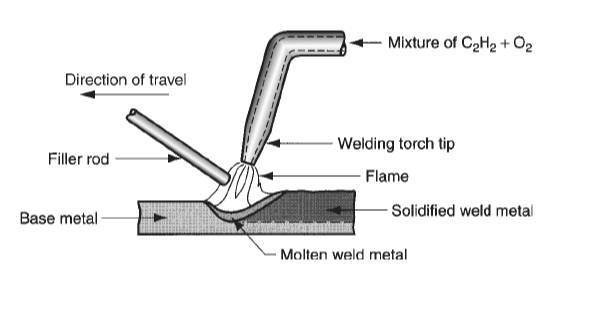
Oxyacetylene welding (OAW) is a type of fusion welding in which oxygen and acetylene are used to create a high-temperature flame. A welding torch directs the flame Sometimes pressure is provided in OAW between the contacting part surfaces, and other times a filler metal is added. The illustration below shows a typical OAW operation.
Generally, filler metal is utilized as a rod, with diameters ranging from 1.6 to 9.5 mm (1/16–3/8 in). The filler's composition ought to match the composition of the base metals. A flux coating, which helps to clean the surfaces and inhibit oxidation, is frequently applied to the filler to improve the weld connection. Because it can reach temperatures up to 3480 °C (6300 ° F), acetylene (C2H2) is the fuel that the OFW group uses the most. Two phases of the chemical reaction between acetylene and oxygen form the flame in OAW. The reaction that follows defines the initial stage:
C2 + H2 + O2 = 2CO + H2 + heat
The second stage of the reaction is triggered by the flammable nature of the products generated above:
2CO + H2 + 1.5 O2 = 2CO2 + H2 O + heat
The oxyacetylene flame that the torch emits shows the two stages of combustion. The neutral flame that results when the acetylene and oxygen mixture is in the 1:1 ratio, as stated in the Equation above, is depicted in the figure below.
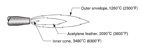
The dazzling white core cone of the flame represents the first step of the reaction, while the practically colorless outer envelope, with hints of blue and orange, represents the second stage. The inner cone's tip is where the flame reaches its highest temperature; the temperatures in the second stage are slightly lower. The outer envelope expands and covers the work surfaces to be joined throughout the welding process, protecting them from the surrounding air.
The two stages of combustion release a total of 55 * 106 J/m3 (1470 Btu/ft3) of acetylene heat. However, power densities and heat transfer factors in oxyacetylene welding are relatively low; f1 = 0.10 to 0.30, due to the temperature distribution in the flame, the way the flame spreads over the work surface, and losses to the air.
Oxyhydrogen Welding (OHW)
Oxyhydrogen (OHW) welding is a type of oxyfuel gas welding in which oxygen and hydrogen are used. With a flame that reaches about 2660 °C (4820 °F), it operates at a lower temperature than oxyacetylene welding.
The combustion reaction is simple:
2H2 + O2 = 2H2O
Low-melting metals such as aluminum, magnesium, and lead, and their alloys are melted and welded virtually exclusively using this technique. The procedure can be used for extremely delicate, accurate work, such as combining the intricate parts of jewelry and electronic assemblies, because the low-temperature, practically invisible oxyhydrogen flame can maintain its very small size without creating carbon soot. In complex applications, where a water electrolysis process can produce hydrogen and oxygen, oxyhydrogen welding is a particularly practical method.
Pressure Gas Welding (PGW)
This is a unique OFW method that is identified not by fuel gas but by the kind of application. Pressure gas welding (PGW) is a type of fusion welding in which the two components are heated with a suitable fuel mixture (often oxyacetylene gas) to achieve coalescence over their full contact surfaces. The surfaces are then bonded together by applying pressure. A typical use is shown in the figure that follows.
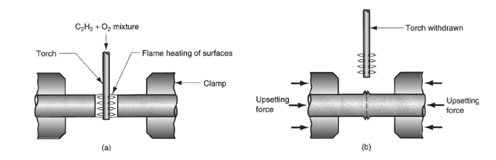
(a) heating the two components and (b) applying pressure to weld them together.
Parts are heated to the point where surface melting occurs. After that, the burning torch is removed, and the components are pressed together and kept under high pressure to allow for solidification.
In PGW, filler metal is not utilized. Pressure gas welding is utilized to create upset welds in butt joints by heating them with an oxyfuel flame and then pressing them together to achieve the necessary forging action. This technique produces reliable welds in plain carbon steel, low-carbon, and high-carbon steels, low-alloy and high-alloy steels, as well as some nonferrous metals It's also effective for joining dissimilar metals. Though gas metal arc welding has completely supplanted the technique, pressure gas welding still works well for mechanized tasks like pipe welding.
Oxyfuel gas welding equipment
The schematic illustration of the minimal basic equipment required for oxy-fuel gas welding is provided in the figure below.
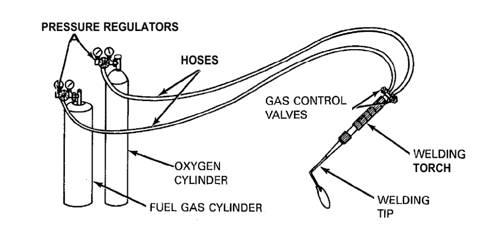
This equipment configuration is entirely independent. It is made up of fuel gas and oxygen cylinders that are equipped with hoses to transfer the gases to the torch, a torch and tip combination to modify the gas mixtures and create the proper flame, and a gas regulator to lower the pressure in the cylinders. Every one of these components is important for the regulation and distribution of the heat required for welding. For numerous heating processes, including torch brazing, the same basic equipment is utilized. The equipment can be easily converted to manual or carriage-controlled oxygen cutting by simply changing the torch and tip combination.
Welding Torches
The components of a standard welding torch include the tip assembly, mixer, and torch handle. It offers a way to connect a range of welding tips or other equipment, a way to individually control the flow of each gas and a handy handle for adjusting the flame's direction and movement. A schematic depiction of the essential components of a welding torch is shown in the figure below.
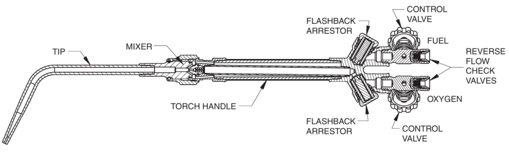
The gases travel via distinct openings in the torch handle, the control valves, and finally the torch head. They subsequently go via a mixer assembly, where fuel gas and oxygen are mixed together before exiting through a tip orifice. A basic tube with a front end narrowed to create a suitable welding cone is depicted as the tip. To make leak-tight installation easier, sealing rings or surfaces are attached to the mixer seats or the torch head.
Torch Handle
The oxygen and fuel gas mixing and flow controls are housed within the welding torch handle. There are many different shapes and sizes of torch handles available, ranging from small sizes for very light applications (low gas flow) to exceptionally hefty types (high gas flow) that are typically employed for targeted heating operations.
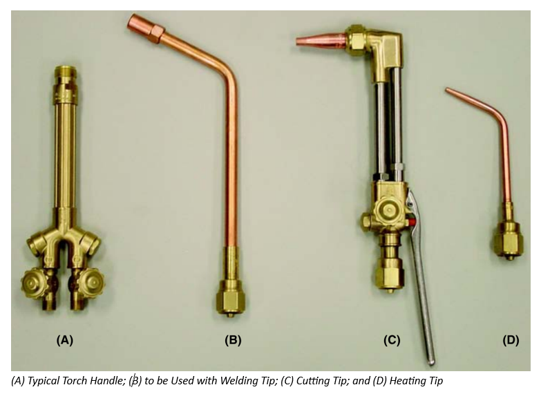
Torch handles are compatible with a range of special-purpose nozzles, cutting attachments, heating nozzles, and mixer and welding tip designs. In the figure below, a standard torch handle and accessories are displayed.
Gas Mixers
The primary purpose of the gas mixer is to thoroughly mix the oxygen and fuel gas to ensure full combustion. In order to help stop the flame from flashing back into the mixer or tip, mixers are designed to function as heat sinks. The two most widely used types of oxygen-fuel gas mixers are the injector, or low-pressure type, and the positive-pressure type, also known as equal-pressure or medium-pressure.
Tips
The section of the torch through which gases pass immediately before they ignite and burn is called the welding tip. With the tip, the welder may optimize the flame's guidance and direct it towards the job.
Typically, nonferrous metals with high thermal conductivity, like copper alloys, are used for oxyfuel gas welding tips in order to lower the possibility of overheating. The two most common methods for creating tips are swaging tubing over a mandrel to the appropriate diameter or drilling bar stock to the appropriate aperture size. For the proper flame cone to be produced, both types of bores must be smooth. It is important to ensure a clear view of the welding operation and ease of usage by shaping the front end of the tip.
Hoses
Hoses used in oxyfuel gas welding and related operations are made especially to satisfy the utility and security specifications required by this service. The hoses used in welding need to be flexible for maximum movement and ease of manipulation. At moderate temperatures, they must also be able to sustain high line pressures. A check valve for each hose should be located at the regulator and another at the torch. Check valves are used in the hose and regulator to stop flashbacks.
Regulators
A regulator is a mechanical device that, despite variations in the pressure at the source, keeps the distribution of a gas at a relatively constant lower pressure. Adjustable pressure reducers with an automatic start-up function are the regulators used in oxyfuel gas welding and related applications. With a few small exceptions, every regulator functions according to the same fundamental idea. Based on their intended use, they are classified into various application categories based on their capacity to handle different gases, pressure ranges, and volumetric flow rates.
Advantages and Limitations
One significant benefit of oxyfuel gas welding is the welder's ability to regulate temperature and heat input without the need for filler metal. The size, shape, and viscosity of the weld pool can all be regulated by the welder. Oxyfuel gas welding equipment is inexpensive, typically portable, and adaptable enough to be utilized for a range of related tasks, including brazing, braze welding, soldering, bending and straightening, preheating, and post-heating. An extensive range of special application accessories, multi-flame heating nozzles, and cutting attachments significantly increase the total versatility of the basic oxyfuel gas welding equipment. From an initial investment perspective, the oxyacetylene process is especially appealing due to its adaptability.
When fabricating heat-treated high-strength steels, oxyacetylene welding is generally not advised, particularly when the steels are still in the heat-treated state. Oxyacetylene welding's slow heat input rate can degrade the characteristics of the heat-treated base metal when welding quenched and tempered steels by causing metallurgical changes in the heat-affected zone. These metals should be welded using one of the arc welding procedures.
Welding Quality and Inspection
Visual examination is the major technique of inspection for oxyfuel gas welds, albeit it is not always a reliable indicator of weld quality. There are two general categories into which discontinuities can be divided: those that are visible to the naked eye and those that are not.
A visual inspection of a weld's underside can determine if penetration is complete and if there are excessive metal globules present. Poor torch and welding rod handling, large root faces, excessive welding rates, and inadequately beveled edges can all contribute to incomplete joint penetration.
It is easy to spot oversized and undersized welds. The presence or absence of reinforcement in a weld can be assessed using weld gauges. It is typically possible to see undercut or overlap at the sides of the welds through eye inspection.
Excessive grain growth and the presence of hard patches cannot be visually identified, even though other discontinuities like partial fusion, porosity, and cracking may or may not be visible externally. Gas or dirt inclusions, fast transit, or inadequate heating of the base metal can all lead to incomplete fusion. Entrapped gases, typically carbon monoxide, cause porosity. This can be prevented by carefully controlling the flame and providing enough fluxing when necessary. The metallurgical features of the weldment lead to hard patches and cracking.
Typical Applications
Many commercial ferrous and nonferrous metals and alloys are suitable for use with oxygen fuel gas welding. However, physical dimensions and chemical composition may restrict the weldability of specific materials and workpieces, as is the case with every welding process. The temperature range that the metal is subjected to during welding nearly exactly matches the original casting or manufacturing process. The qualities that came from earlier heat treatment or cold working are lost by the base metal in the weld area.
Oxyfuel gas welding is a technique that can be used to join carbon steels, low-alloy steels, and the majority of nonferrous metals. Plain carbon steels are often easy to weld and present little challenge to the welder. The equipment available for heat-treating materials after welding restricts the number of materials that may be welded, including high-carbon and high-alloy steels. When the work piece's dimensions or composition allow for post-heat treatment procedures, these metals can be successfully welded. In various materials, different combinations of fluxing, heat-treating, pre-heating, and welding methods result in sound welds.
Oxyfuel gas welding is a method that can be used to repair metals of significant thickness as well as common assemblies found in maintenance work. Repairing very thick cast iron machinery frames usually involves brazing or using a cast iron filler rod during the welding process. For refractory or reactive metals, the oxyfuel gas welding method is not advised.
References
Groover, M.P., 2010. Fundamentals of Modern Manufacturing: Materials, Processes, and Systems. 4th ed. Hoboken, NJ: John Wiley & Sons, Inc.
American Welding Society, 2004. Welding Handbook. Ninth Edition. Volume 2. Welding Processes, Part 1. Edited by Annette O’Brien. American Welding Society.