
Electron beam welding (EBW) is a technique that achieves coalescence using a focused stream of high-velocity electrons directed at the weld joint. With a few exceptions, the operation is carried out without the assistance of pressure or shielding gas. Three variations of this procedure exist nonvacuum electron beam welding (EBW-NV), medium-vacuum electron beam welding (EBW-MV), and high-vacuum electron beam welding (EBW-HV). Because nonvacuum electron beam welding is carried out at pressures close to atmospheric pressure, it is occasionally referred to as atmospheric electron beam welding.
Electron Beam Welding Fundamentals
A beam of high-energy electrons is impinged upon the workpiece during electron beam welding to create a fusion weld with heat generated. Having a negative charge and relatively little mass, electrons are the fundamental particles of matter. Accelerating electrons to velocities between 30% and 70% of the speed of light elevates them to a high-energy state, which is required for electron beam welding.
Much like a cathode ray tube (CRT), which continually scans the surface of a luminous screen with a low-intensity electron beam to produce a picture, an electron beam welding system works in roughly a similar way. Weld joints are continually bombarded with a high-intensity electron beam in electron beam welding systems. The input energy produced when the electrons hit the metal causes localized heating and melting of the weld joint. An electron gun, which usually consists of an anode, a bias voltage control electrode, and a thermionic electron emitter of some kind, is used to create the electron beam in each of these scenarios.
It is customary to refer to the electron emitter as the gun's cathode or filament and the bias voltage control electrode as the gun's grid or grid cup. In order to concentrate and deflect this beam, a number of other devices are also supplied downstream of the gun, including focus and deflection coils.
In electron beam welding (EBW), the entire beam-generating system, which includes the gun and electron optics, is referred to as the electron beam gun/column assembly or just the electron beam gun column.
Operating Principles
The assembly of the electron beam cannon and column forms the core of the electron beam welding process. The figure below depicts a simplified version of the gun column:
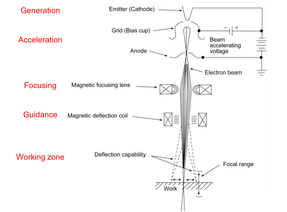
Electrons are produced when a negatively charged emitting material is heated to a temperature within its thermionic emission range. This leads to the electrons "boiling off" the emitter, which can also refer to the cathode or filament, and accelerates towards the positively charged anode by electrostatic forces. The electrons are accelerated and shaped into the beam by the electrostatic field geometry created by the carefully arranged grid (bias cup) surrounding the emitter. An aperture in the anode allows the beam to leave this area of the gun.
Beam-shaping electrode and emitter in a diode (cathode-anode) gun are at the same electrical potential and together are called cathode. Due to the differing potentials of the emitter and beam-shaping electrode in a triode (cathode, grid, and anode) gun, the beam-shaping electrode can be biased to a little more negative value than the emitter in order to control the beam current flow. The beam-shaping electrode in this instance is referred to as the grid, while the emitter alone is referred to as the cathode (or filament). Beam generation (acceleration and shaping) is achieved totally independently of the workpiece in both scenarios since the anode is integrated into the electron cannon. Using cannon voltages between 25 and 200 kilovolts (kV), the electron beam is accelerated to speeds between 30 and 70 % of the speed of light as it leaves the gun.
After that, the beam keeps moving in the direction of the workpiece. As the travel distance rises, the beam gradually broadens after exiting the gun, as seen in the above Figure. Due to their thermal energy, all of the electrons in the beam have some radial velocity, and they also all undergo some degree of mutual electrical repulsion, which causes the divergence. The interaction of electrons with the residual gas atoms and molecules in the beam path also produces some minor effects. Lower energy levels utilized in welding applications do not cause this phenomenon to occur, however, electrons at much higher energy levels will charge the particles and generate a self-focusing effect.
The beam is therefore converged and focused into a small point on the workpiece using an electromagnetic lens system in order to counteract this intrinsic divergence effect. According to the above figure, the focused beam has a useful focal range (or depth of focus) that extends over a distance of around 25 mm (1 in.) since the beam's divergence and convergence angles are quite small.
The following four fundamental variables, when applied to a welding joint, govern the rate of energy input:
- Beam current: the quantity of electrons striking the workpiece in a second;
- Beam accelerating voltage, or how fast these electrons are traveling;
- The focal beam spot size, which is the amount of beam concentration at the workpiece; and
- Welding speed: The pace at which the electron beam or workpiece travels.
Commercially available electron beam gun/column assemblies can produce maximum beam accelerating voltages and currents between 25 kV and 200 kV for the gun and 1 mA to 1000 mA for the current. These systems' electron beams can typically be concentrated to minimum diameters of 0.25 mm to 0.76 mm, or 0.01 inch [in.] to 0.03 in.
As much as 100 kilowatts (kW) can be obtained as the final power output from these units. One can get power densities as high as 1.55 × 10⁴ W/mm2 (107 W/in.2). Similar to what may be achieved by laser beam welding, these power densities are much higher than those made possible by arc welding procedures.
The highest power density that an electron beam system can apply to the workpiece indicates the system's prospective welding capabilities. The lowest focal point size that the system can achieve and the maximum beam power (current multiplied by voltage) determines this comparative factor. Although they have been constructed, electron beam welding systems with beam power levels up to 300 kW and power densities exceeding 1.55 × 10⁵ W/mm2 (108 W/in.2) have never been put to use commercially.
The figure below shows how an electron beam may quickly penetrate a solid workpiece or butt joint at power densities on the order of 1.55 × 10² W/mm2 (105 W/in.2) and higher, generating a vapor cavity termed a keyhole that is surrounded by molten metal. As the beam moves forward along the joint, molten metal flows around the keyhole and solidifies at the back to form weld metal. In keyhole applications, a highly narrow heat-affected zone is formed and the joint penetration is far deeper than wide.
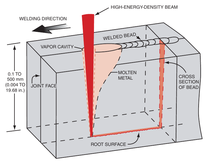
The angle at which the beam impinges on a workpiece's surface can influence the final angle at which the keyhole is made with regard to that surface since the electron beam weld is the consequence of a keyhole formed by the beam. The resulting weld metal zone is also influenced by the incidence angle.
Electron beam welding variations
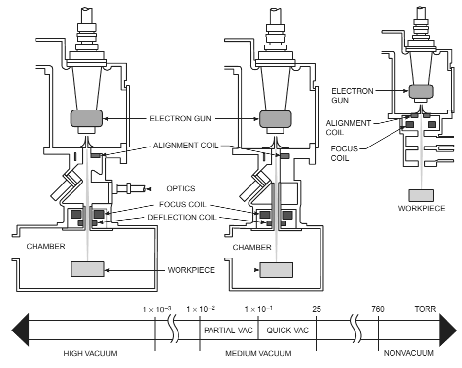
Electron beam welding is usually performed in three fundamental variations: high-vacuum (EBW-HV), medium-vacuum (EBW-MV), and nonvacuum (EBW-NV). The ambient pressure at which welding is conducted is the primary distinction between various process modes. The hard vacuum welding method, also known as the high-vacuum version, operates below 0.13 Pa (10–3 torr).4 The pressure range for medium-vacuum welding is 0.13 Pa to 3.3 × 10³ Pa (10–3 torr to 25 torr). In this range, the pressure span between approximately 0.13 Pa and 1.3 × 10² Pa (10–3 torr to 1 torr) is sometimes referred to as partial vacuum or soft vacuum, while the pressure span between approximately 1.3 × 10² Pa and 3.3 × 10³ Pa (1 torr to 25 torr) is referred to as rapid vacuum. For steady and effective operation, the pressure in the electron beam cannon column needs to be maintained at a high vacuum, which is 1.3 × 10⁻² Pa (10–4 torr) or less, in any situation.
The electron beam in nonvacuum electron beam welding systems is created in a high vacuum and then goes through a sequence of orifices that are specifically made to divide many differentially pumped chambers. The beam eventually exits into a working region that is at atmospheric pressure or slightly below. For nonvacuum electron beam welding outdoors, beam-accelerating voltages greater than 150 kV are typically required. Beam-accelerating voltages below 150 kV can be used, nevertheless, if the ambient environment is composed of a gas such as helium.
The three basic modes of electron beam welding are shown in the figure below.
High-Vacuum Electron Beam Welding
For all electron beam guns, a high vacuum of 1.3 × 10⁻² Pa [10–4 torr] or less is necessary. The gun itself cannot function efficiently at pressures much higher than 1.3 × 10⁻² Pa (10–4 torr), even though unique techniques enable the beam to enter environments of higher pressure.
In a high-vacuum environment, electron beam welding offers the following main benefits:
- Weld shrinkage and deformation can be minimized by achieving maximum joint penetration and minimum weld width.
- Because of the beam's high energy density and the ensuing keyhole form of melting, welds have a high depth-to-width ratio;
- The clean environment that a high vacuum creates allows for the weld metal to be as pure as possible; and
- The operator's capacity to monitor the welding process and weld joints with restricted accessibility is enhanced by the extended gun-to-workpiece distances achievable under high vacuum.
Electron scattering from electron beam collisions with residual gas molecules in the beam's path is reduced in a high-vacuum environment. The frequency of these collisions is directly proportional to the gas molecules' concentration and the total distance traveled. When lengthy travel distances must be used, the reduced electron scattering is especially advantageous.
The weld metal's purity is increased as a result of the high vacuum, which reduces the amount of oxygen and nitrogen that the hot weld zone is exposed to while also forcing the gases that are created during welding to quickly escape the region. Consequently, compared to medium- and non-vacuum process variants, high-vacuum welding is more appropriate for welding extremely reactive metals. Production rates are severely constrained by the pumping times necessary to create a high vacuum in the chamber. If many assemblies can be welded in a single load in a small-volume chamber, then this pump-down limitation can be somewhat mitigated. The size of the chamber determines the maximum number of components that can be welded per batch load. Because of this, high-vacuum welding is typically more appropriate in situations with relatively low production rates. Workpiece transfers using "air-to-air" techniques have been devised in a variety of ways, enabling the movement of component assemblies into and out of high-vacuum areas without opening the chamber. High-vacuum EBW can be used in some high-production joining applications, including the welding of bimetallic saw blades, due to these techniques.
Medium-Vacuum Welding
Ability to weld without pumping the welding chamber to an extremely low pressure (high vacuum) is a key component of medium-vacuum electron beam welding. Minimal chamber size can result in a few seconds of necessary pumping time, which is crucial for cost-effective processing. Medium-vacuum welding is the best option for high-volume assembly production involving repetitive welding processes when a minimum-volume welding chamber is available. When gears are properly welded to shafts in their final machined or stamped state, for instance, close dimensional tolerances are maintained and no additional finishing is needed. Figure following depicts this application.
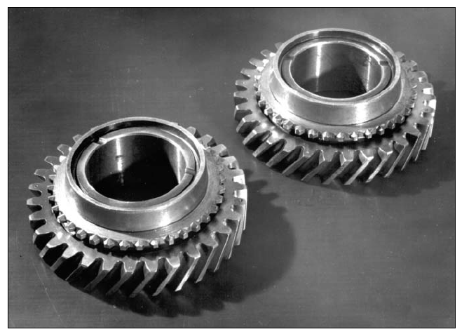
Gears Welded with Medium-Vacuum EBW
Medium-vacuum EBW is less effective than high-vacuum EBW for welding reactive metals because it operates at pressures where there is a large concentration of air (100 parts per million). Reactive metals require an extremely pure welding environment in order to maintain their properties. The electrons in the beam are additionally scattered by the increased air concentration, which increases the beam width and lowers the power density. Compared to identical welds made under high vacuum, these welds are somewhat wider, more tapered, and have less joint penetration.
Nonvacuum Welding
The main benefit of electron beam welding without vacuum, or atmospheric welding, is that the workpieces don't have to be sealed inside a vacuum chamber. Higher production rates and cheaper per piece are achieved by eliminating the time required to empty a chamber. Furthermore, the weldment's size is not constrained by the chamber's size. These benefits come at the cost of not being able to reach the gun-to-workpiece distance, the depth of fusion, or the depth-to-width ratio of the weld that can be accomplished in a vacuum. Even with inert gas shielding, the environment during welding is not as pure as it is during high- and medium-vacuum welding.
While a vacuum container for the workpiece is not necessary, radiation shielding of some kind must be installed to shelter workers from the X-rays that are produced when the electron beam hits the material. In contrast to high- and medium-vacuum versions, nonvacuum welding requires different operating conditions. As ambient pressure rises, beam dispersion increases quickly. The smallest nonvacuum gun-to-workpiece distance that can be used, even in a helium gas environment, is less than 38 mm (1.5 inches). This limits the possible shapes of the workpieces to those that don't obstruct the gun column. In nonvacuum electron beam welding, the gun-to-workpiece distance, travel speed, beam power level, and surrounding atmosphere all have an impact on the joint penetration that is accomplished.
At power levels greater than 50 kW, nonvacuum electron beam welding seems to exhibit more effective joint penetration. The lower gas density caused by the high-energy electron beam's local heating is the cause of this outcome.
Advantages of Electron Beam Welding
Electron beam welding offers exceptional performance possibilities. Numerous joining issues are resolved by the excellent control capability, high power density, and high-quality environment. The following are some of the benefits of electron beam welding:
- Because EBW turns electrical energy directly into beam output energy, the method is incredibly efficient;
- Since electron beam welders have a high depth-to-width ratio, single-pass welds can be accomplished in thick joints;
- 3. Compared to arc welding, the heat input per unit length for a given depth of penetration can be significantly lower, leading to a narrower weld zone, less deformation, and less harmful thermal effects in the workpiece;
- Reduced oxygen and nitrogen contamination of the weld metal is achieved while welding in a high-purity (vacuum) atmosphere.
- Welding is frequently possible in areas that would not be accessible otherwise due to the vacuum's capacity to project the beam over a few feet;
- Because the concentrated heat source's high melting rates enable rapid travel speeds, welding times can be cut, productivity can rise, and energy efficiency can be increased;
- Thin and thick plates can be welded in one pass without the need for filler metal if the butt joints are suitably square;
- Vacuum can be maintained inside the weldment when hermetic closures are welded using the high- or medium-vacuum modes of operation;
Limitations of Electron Beam Welding
The following are a few electron beam welding limitations:
- EBW equipment has significantly higher capital costs than arc welding equipment, however in high-volume manufacturing, the overall cost per piece can be very competitive;
- Except in certain cases, precise machining of the joint edges, precise joint alignment, and appropriate fit-up are necessary for preparing for welds with high depth-to-width ratios;
- To capitalize on the electron beam's small size, the root opening needs to be as small as possible;
- Highly restricted, low-ferrite austenitic stainless steel may crack as a result of the fast solidification rates attained;
- The size of the vacuum chamber and the time required to evacuate it will affect production costs because high- and medium-vacuum welding needs the chamber to be large enough to hold the assembly;
- Porosity and cavities in the weld root can occur in partial-penetration welds with high depth-to-width ratios;
- Magnetic fields deflect the electron beam, hence nonmagnetic or appropriately degaussed metals should be used for tooling and fixturing close to the beam path; this will affect manufacturing costs;
- When using the nonvacuum mode of electron beam welding, the product design in regions immediately next to the weld joint may be restricted due to the distance restriction from the bottom of the electron beam gun column to the workpiece. To guarantee that staff members are not exposed to X-rays produced by EBW, radiation shielding must be maintained for all EBW modes;
- When using nonvacuum EBW, or other welding techniques where hazardous materials are generated, enough ventilation is necessary to guarantee the correct removal of ozone and other harmful gases produced.
Equipment for Electron Beam Welding
An electron beam gun/column assembly, one or more vacuum pumping systems, and a power supply are used in high-vacuum, medium-vacuum, and nonvacuum electron beam welding equipment. The workpieces in evacuated welding chambers are used in high-vacuum and medium-vacuum systems. The electron beam gun column needs a vacuum environment, even if the nonvacuum mode does not require the workpieces to be placed in a chamber.
High-voltage equipment, or equipment with gun columns that have beam-accelerating voltages higher than 60 kV, can be used to carry out all three types of electron beam welding. It takes beam-accelerating voltages larger than 150 kV to achieve nonvacuum electron beam welding directly in air. Both high- and medium-vacuum welding can be carried out using low-voltage equipment, such as those equipped with gun columns that use voltages of 60 kV or less to accelerate beams.
Because high-voltage gun columns are typically somewhat massive, they are typically positioned outside the welding chamber and can only move in a limited amount of a tilting or translational direction, or both. Gun columns with low voltage are often compact. A unit can have up to five axes of combined translational motion if it is installed internally; other units are fixed externally.
Electron Beam Guns
Electron beam welding guns are typically operated under space-charge limitations. When a gun is operated in this manner, the beam current it produces at any accelerating voltage is proportional to the accelerating voltage's 3/2 power (I = KV3/2). The constant of proportionality, K, is determined by the geometry of the gun.
Gun configuration, emitter properties, total power capabilities, and focusing provisions all affect how well a gun performs. If there is enough beam power available to allow for fast travel times and if the beam power density is high enough to create and sustain a keyhole to the necessary depth of joint penetration, then notably tiny welds can be made for a given metal and joint thickness.
Electrons are produced, accelerated, and collimated into a targeted beam using an electron beam gun. The gun's parts and features fall into one of two categories:
- the emitter, which produces electrons, either utilizes a rod or disk filament that is indirectly heated by electron bombardment or induction, or it employs a wire or ribbon filament that is heated directly.
- The elements that shape and form beams are the grid and the anode.
Power Sources
An assembly made up of a high-voltage power source section and one or more auxiliary power source segments provides the high-voltage power required by electron beam welding equipment. The necessary gun beam accelerating voltage is provided by the high-voltage power source section, while the emitter heating and beam current output regulation are supplied by the auxiliary power source segments. The high-voltage power supply is made up of two or more of the following parts, depending on whether the gun is a triode or a diode type:
- The continuous beam-accelerating voltage and total beam current are supplied by a primary high-voltage direct-current (DC) power source.
- a power source for the emitter (filament) that can produce either DC or AC output
- a power source with grid electrodes that controls beam current by impressing a voltage between the bias electrode and the emitter.
Vacuum Pumping Systems
For high- and medium-vacuum welding, vacuum pumping systems are needed to evacuate the electron beam gun chamber, the welding chamber (also known as the workpiece chamber), and the orifice assembly utilized on the beam exit part of gun/column assemblies for medium-vacuum and nonvacuum welding. There are two primary kinds of vacuum pumps in use. One is a mechanical piston or vane type that lowers pressure from one atmosphere to 0.1 torr (1.0 × 10⁻² kPa). The other pump is an oil-diffusion kind that lowers the pressure to 1.3 × 10⁻² Pa (10–4 torr) or less.
Applications of Electron Beam Welding
High precision and high production are the two main application categories for electron beam welding. For high-precision applications, the welding must be done in a high-purity (high vacuum) environment with minimal heat effects and maximum reproducibility to prevent contamination from oxygen or nitrogen, or both. The nuclear, aerospace, aviation, and electronic industries are the primary users of these technologies. Products that are typical include pressure vessels for rocket propulsion systems, hermetically sealed vacuum devices, jet engine components made of specific alloys, and nuclear fuel elements.
High-production applications benefit from the minimal heat input, high speed, high repeatability, and high dependability of electron beam welding when a high-purity environment is not necessary. These permissive circumstances allow semi-finished or finished component welding with either nonvacuum or medium-vacuum equipment. Typical examples are thin-walled tubing, steering columns, frames, gearboxes, and drivetrain and transmission parts for cars.
The "air-to-air" method of high-production EBW is another way to join bimetal strips, which are used in relays, band-saw and hacksaw blades, and other applications. This mode enables welding to be done in both ambient and high-vacuum environments because the product is continuously fed from the atmosphere via a vacuum zone and back to the atmosphere.
The primary use of nonvacuum electron beam welding is in the high-volume manufacturing of industrial components where welding in a vacuum is not practical due to factors like size, composition, or needed hourly production rate. The automobile sector serves as an example of this, as nonvacuum welding is used in many different applications. Figure (A) below displays a driving ring welded to a torque converter turbine bowl assembly.
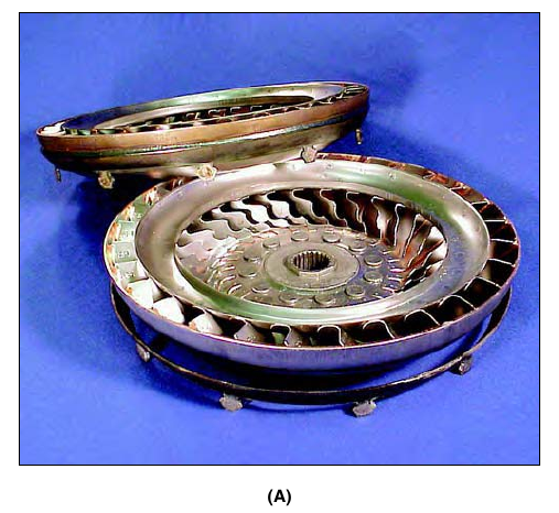
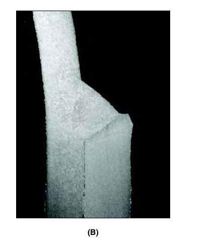
Figure (B) below displays a profile of the nonvacuum electron beam weld created in this application.
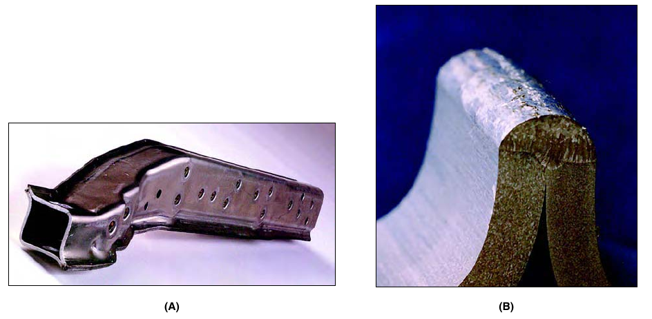
The figure below provides another illustration of nonvacuum electron beam welding. Figure (A) depicts the edge weld in two formed half-shells made of aluminum alloy, and Figure (B) shows a close-up view of the weld. The application is a reduced-weight crossbar section of an automotive instrument panel. In place of the steel item it replaces, this weldment offers a component with an equivalent structural strength. Its weight reduction of 40% and its average welding speed of 12 m/min (450 in./min) are its main advantages over the steel item.
References
American Welding Society, 2007. Welding Handbook: Welding Processes, Part 2. 9th ed. Edited by Annette O’Brien. Associate Editor: Carlos Guzman.