
Overview of brazing and soldering
Brazing and soldering both use filler metals to join two or more metal parts permanently. While disassembling these joints is difficult, it is not impossible. These methods fall between fusion welding and solid-state welding in the range of joining techniques. Like fusion welding, brazing and soldering add filler metal, but they don't melt the base metals, similar to solid-state welding. Despite these similarities, brazing and soldering are generally seen as different from welding. They are especially useful when (1) the metals are difficult to weld, (2) different types of metals need to be joined, (3) the high heat of welding could damage the parts, (4) the joint shape isn't suitable for welding, and/or (5) high strength isn't necessary.
Brazing
Brazing is a joining technique wherein a filler metal is melted and subsequently dispersed between the facing surfaces of the metal components to be bonded via capillary action. Only the filler melts during brazing; the base metals do not melt. The melting temperature (liquidus) of the filler metal, also known as the brazing metal, in brazing is more than 450 degrees Celsius (840 degrees Fahrenheit), but lower than the solidus of the base metal or metals to be connected. The brazed junction will be stronger than the filler metal it was made from after solidification if the joint is correctly designed and the brazing procedure is carried out correctly. The metallurgical bonding that happens between base and filler metals, the geometric constrictions that the base parts impose on the junction, and the minuscule part clearances utilized in brazing are all responsible for this quite amazing result.
Brazing Techniques
Brazing processes are typically classified based on the heating sources or techniques. Currently, popular industrial techniques include the following:
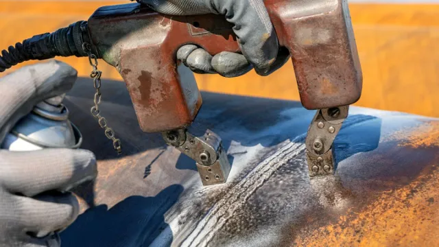
Torch Brazing
Torch brazing involves applying flux to the part surfaces and using a torch to aim a flame against the work near the joint. Usually, oxidation is inhibited by a reducing flame. Filler wire is introduced to the joint, typically in the form of wire or rod, once the work-part joint areas have reached an acceptable temperature. Acetylene, propane, and other gases combined with air or oxygen are fuels used in torch brazing.
Air-natural gas torches emit the least amount of heat and have the lowest flame temperature. In an air-acetylene torch, atmospheric pressure air is combined with acetylene under pressure. For small parts and thin portions, air-natural gas and air-acetylene torches can both be advantageous.
Greater flame temperatures are attained by torches that combine oxygen with natural gas or other cylinder gases, such as propane and butane. These torches can handle a variety of brazing tasks with great success if they are operated with a neutral or slightly decreasing flame. Because they do not overheat the assembly during brazing, oxygen-hydrogen torches are frequently used for brazing aluminum and nonferrous alloys. The joint is also cleaned and protected by an overabundance of hydrogen in the flame.
Torches with several points or flames can be specially built to maximize the rate of heat input; but, in order to prevent localized overheating, the torch must be moved frequently. Single-tip torches with one or more flames can be used for hand torch brazing. Assemblies with components of varying masses benefit greatly from this technique. Depending on the needs of the production, machines with one or more torches—each with one or more flame tips—can be set up for larger-scale operations. These devices have the ability to move both the torches and the workpieces. Refractory-type burners are utilized for air flames and premixed municipal gas.
Furnace Brazing
Furnace brazing, which works best for medium and high production volumes, employs a furnace to provide heat for the brazing process.
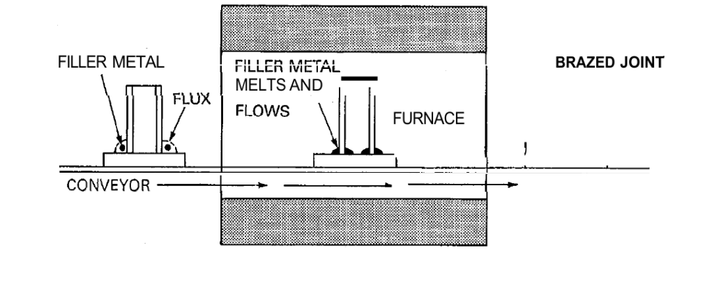
Furnace brazing is widely used in the following situations: (1) parts to be brazed can be preassembled or jigged to hold them in place; (2) brazing filler metal can be placed in contact with the joint; (3) multiple brazed joints are to be formed simultaneously on a completed assembly; (4) many similar assemblies are to be joined; and (5) complex parts must be heated uniformly to prevent the distortion that would result from local heating of the joint area. Furnace brazing is shown in the image below.
Furnace brazing should be done in electric, gas, or oil-heated furnaces with automatic temperature controls that can maintain a temperature within +/-10 °F (+/- 6 °C). It is necessary to offer fluxes or specifically designed atmospheres that carry out fluxing functions.
To prepare parts for brazing, assemble them with the filler metal and flux (if used) positioned in or around the joints. The filler metal can be in the form of wire, foil, filings, slugs, powder, paste, or tape. Then, heat the assembly in a furnace until it reaches the brazing temperature and the brazing process occurs. Once completed, remove the assembly from the furnace.
The preceding Figure illustrates these steps. For both ordinary and specialized brazing procedures, a wide variety of commercial fluxes are available. If the dry powdered flux is spread along the joint, satisfactory results are achieved.
In most instances, flux paste is satisfactory, but occasionally it slows down the brazing alloy's flow. In circulating air furnaces or drying ovens, flux pastes with water can be dried by heating the assembly for five to fifteen minutes at 350 to 400°F (175 to 200°C). The parts' thickness and the quantity of fixturing required to position them will have an impact on how long the brazing takes. If you want to prevent too much interaction between the filler metal and base metal, you should only braze for as long as is required for the filler metal to flow through the joint. A braze can usually be made in one or two minutes at the brazing temperature. If the filler metal remelts temperature is to be raised and joint ductility and strength are to be enhanced through diffusion, a longer brazing temperature will be advantageous. To raise the braze remelt temperature, brazing temperatures are generally held for periods of 30 to 60 minutes.
The brazing furnaces are categorized as follows: (1) batch type that operates in an air or controlled atmosphere; (2) continuous type that operates in an air or controlled atmosphere; (3) retort type that operates in a controlled atmosphere; or (4) vacuum. The temperature control found in the majority of brazing furnaces is of the potentiometer variety, which is linked to thermocouples and contactors or gas control valves. The majority of furnaces are heated electrically by the use of heating elements made of silicon-carbide, nickel-chromium, or refractory metal (Mo, Ta, or W).
It is important that a gas or oil flame not come into direct contact with the pieces when heating them. In order to prevent contamination from oxide dissociation and metal part outgassing, a constant flow of atmosphere gas is maintained in the work zone using controlled atmosphere furnaces. Enough ventilation of the workspace and explosion protection is required if the controlled atmosphere is poisonous or combustible.
Induction Brazing
Induction brazing derives its heat from an electric current induced in the parts to be brazed, hence its name. In this procedure, components are not a part of the electrical circuit; instead, they are positioned inside or close to an alternating current-carrying water-cooled coil. The parts that require heating function as the transformer's short-circuited secondary, while the work coil that is linked to the power supply serves as the primary. The resistance of the parts to the induced currents, which come from the transformer operation, is what causes the heating. This is true for components that are magnetic and nonmagnetic.
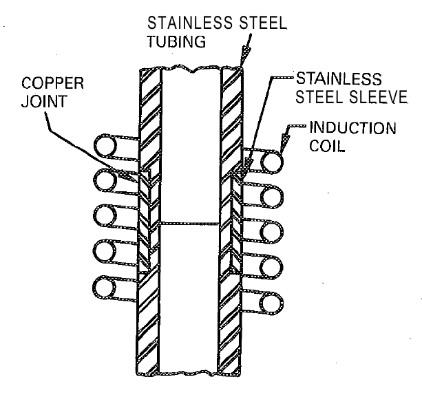
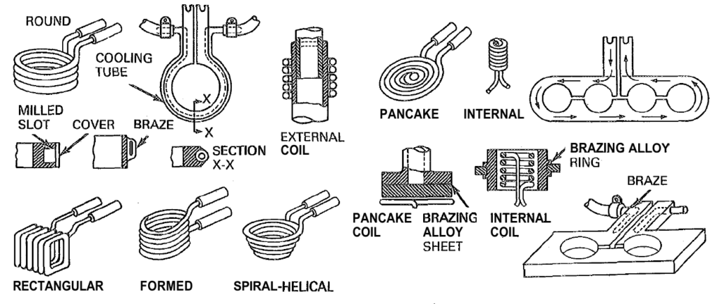
In order to guarantee that the surfaces of every joint member achieve the brazing temperature at the same time, the brazing filler metal is pre-positioned, and the joint and coil setup must be carefully designed. Generally, flux is employed unless a certain environment is supplied to accomplish the same goal. Vacuum tube oscillators produce higher frequencies in induction brazing than solid-state generators, which typically produce frequencies between 10 to 450 kHz. Sizes for induction generators range from one kilowatt to several hundred kilowatts. As seen in the figure below, various designs of induction brazing coils can be used.
A conveyor-type coil can be used to continually process assemblies in holding fixtures to reach brazing temperature, or a single generator can power several workstations in succession via a transfer switch. When handling a large number of pieces automatically, induction brazing is the best option since it can heat very quickly—processing periods are often only a few seconds.
Resistance Brazing
Electric current passing through the electrodes and the joint that needs to be brazed produces the heat required for resistance brazing. The joints' component pieces are incorporated into the electrical circuit. It is convenient to replace or face-feed the brazing filler metal. When fluxing, the conductivity of the fluxes is taken into consideration. Unless a special environment is introduced to serve the same purpose, flux is used. Proper current and pressure are delivered while the components to be brazed are held between two electrodes. Up until the joint solidifies, the pressure needs to be kept on. When maintaining the necessary pressure, it is possible for both electrodes to be situated on the same side of the joint and to have an appropriate support. Brazing filler metal comes as a powder, paste, shims, washers, rings, and preplaced wire forms. Face feeding is feasible in a few cases. Because they self-flux, the copper-phosphorus filler metals are the most suitable for copper and copper alloys. It is possible to employ silver base filler metals, although an atmosphere or flux is required. Usually, immediately before the assembly is put into the brazing fixture, a very thin mixture of wet flux is added. Because they are insulators and won't allow enough current to pass, dry fluxes aren't employed.
The brazed pieces ought to be clean. After assembly, the components, flux, and brazing filler metal are put inside the fixture, and pressure is applied. The flux and filler metal melt and flow as the current travels through the electrodes, which are frequently heated to incandescence. To achieve uniform quick heating throughout the pieces, the current needs to be regulated. If you overheat, there's a chance you'll oxidize or melt the work and the electrodes will break down. The duration of brazing increases with insufficient current. The greatest mix of quick heating and acceptable electrode life can be obtained by experimenting with electrode compositions, geometry, and voltage.
Flux removal will be aided by quenching the components from a high temperature. In order for the braze to hold the parts together, the assembly must first cool down enough. It could be wise to quickly quench the components while they are still in the electrodes while brazing insulated conductors in order to prevent the surrounding insulation from overheating. Clamps that are cooled by a water shield the insulation from harm.
The most suitable joints for resistance brazing are those with a simple form. If the area to be brazed is large, irregular, or significantly longer in one dimension, it will be challenging to achieve uniform current distribution and, thus, uniform heating. The design of the parts to be resistance brazed should allow pressure to be applied to them at brazing temperature without distorting them. The components should be made as self-nesting as feasible to avoid the need for dimensional features in the fixtures.
In order for the filler metal to melt and flow through the joint, parts must also be able to move freely. Each arm's electrode is fastened to a pair of tongs or clamps as part of the apparatus. To prevent overheating, it is best if the tongs are water-cooled. Indeed, the arms are. cables that transmit current and are connected to a transformer by leads. The secondary circuit of a stepdown transformer, which can supply enough current at low voltage (2-25 V), is a typical source of current for resistance brazing. Larger jobs will require currents that range from hundreds of amps to roughly 50 A for small, sensitive tasks. Commercial equipment is available for resistance brazing.
High-resistance electrical conductors, such as graphite or carbon blocks, tungsten or molybdenum rods, or occasionally even steel, are used to make electrodes for resistance brazing. The electrodes produce the majority of the heat required for brazing, which conduction transfers into the work. Attempting to generate heat just from the resistance of the workpieces is usually ineffective.
Dip Brazing
In dip brazing, heating is achieved by either a molten metal bath or a molten salt bath. Both techniques include submerging assembled components in the baths inside a heating pot. The components solidify after being taken out of the bath. The filler metal is preloaded onto the assembly and fluxing chemicals are introduced into the molten slurry when using the salt bath process. Melted filler metal serves as the heating medium in the metal bath procedure, where it is absorbed into the joint by capillary action while submerged. On the surface of the molten metal bath, a flux cap is kept in place. Dip brazing is a quick heating cycle technique that can be used to braze many joints on one item at a time or on many parts at once.
Infrared Brazing
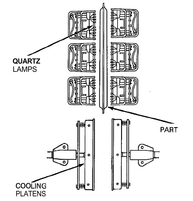
A type of furnace brazing known as infrared brazing could be defined as using radiation from long-wavelength visible light to provide heat. Heat is produced by high-intensity quartz lamps that emit invisible radiation up to 5000 watts of radiant energy. The amount of heat input fluctuates inversely with the square of the distance from the source; however, most lamps are not made to fit the shape of the object that needs to be heated.
Radiation is directed onto the components by concentrating reflectors. The assembly and the lamps are put inside a bell jar or retort that can be sealed shut or filled with inert gas for vacuum brazing or inert-gas protection. Then, as shown by thermocouples, the assembly is heated to a predetermined temperature. An infrared brazing configuration is depicted in the figure below. After brazing, the component is transferred to the cooling platens.
Braze Welding
The kind of joint to which this procedure is applied sets it apart from other brazing methods. Braze welding is used to fill in a more traditional type of weld connection, such as the V-joint depicted in the figure below.
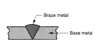
Compared to brazing, more filler metal is deposited, and there is no capillary action. Unlike traditional fusion welding, when the base metal melts and becomes fused into the joint, braze welding creates a joint made completely of filler metal. Repair work is the main use of braze welding.
Process advantages and disadvantages
Similar to any joining method, brazing has benefits and drawbacks. Brazing has a variety of advantages depending on the heating technique employed, but it is usually less expensive, especially when done in big quantities. Brazed joints have the major benefit of being able to be dismantled later if necessary. Unlike other joining procedures, it can also join different kinds of metals without melting the basic components. Several hundred pieces with numerous braze joints can be handled by this method at once. Heat treatment can be incorporated into the brazing cycle and parts are kept clean when protective atmosphere brazing is used.
However, adverse interactions may result from the brazing process, which includes the flow of molten metal between the components. Base metal erosion may happen, depending on the materials and base metal thickness. Although in some circumstances this erosion may not be significant, it can damage joints in thin or strongly stressed materials, rendering them unfit for their original purpose. Furthermore, excessively brittle joints may arise from the development of brittle intermetallic phases. The requirement for highly competent technicians is another drawback, especially when employing a gas torch with filler metal that has a high melting point and certain hand-brazing techniques. Despite these challenges, brazing can be a useful joining solution for many situations where fusion welding is not viable because of strength or cost issues if the right joint design, filler metal choice, and technique are used.
Applications
Many different industries employ brazing as a production process: automotive (for example, joining pipes and tubes), electrical equipment (for example, joining wires and cables), cutting tools (for example, brazing cemented carbide inserts to shanks), and jewelry creation. Moreover, brazing is used by plumbing and heating companies as well as the chemical processing industries to connect metal tubes and pipes. In almost every industry, the procedure is widely utilized for maintenance and repair work.
SOLDERING
Similar to brazing, soldering is a joining technique where a filler metal that has a melting point (liquidus) of no more than 450 °C (840 °F) is melted and spread between the face surfaces of the metal components that are to be joined by capillary action. The filler metal wets and combines with the base metal to form a metallurgical link, just like in brazing, but there is no melting of the base metals. There are many similarities between brazing and soldering details, including heating techniques. Prior to soldering, surfaces need to be thoroughly cleaned to remove any oxides, oils, and other debris. The faying surfaces need to be heated and treated with the proper flux. Solder, a filler metal, is poured into the joint and spreads amongst the parts that fit together tightly.
Regardless of whether the solder contains any tin, in some applications the solder is precoated onto one or both of the surfaces—a procedure known as tinning. Except in situations where the surfaces are tinned, where a clearance of roughly 0.025 mm (0.001 in) is utilized, typical soldering clearances range from 0.075 to 0.125 mm (0.003–0.005 in). The flux residue needs to be eliminated following solidification.
Soldering Techniques
Many of the techniques used in both processes are similar, even though soldering requires less heat and lower temperatures than brazing. These methods include dip soldering, infrared soldering, resistance soldering, induction soldering, towel soldering, and furnace soldering. Other soldering methods unrelated to brazing are covered in this section. These methods consist of hand soldering, wave soldering, and reflow soldering.
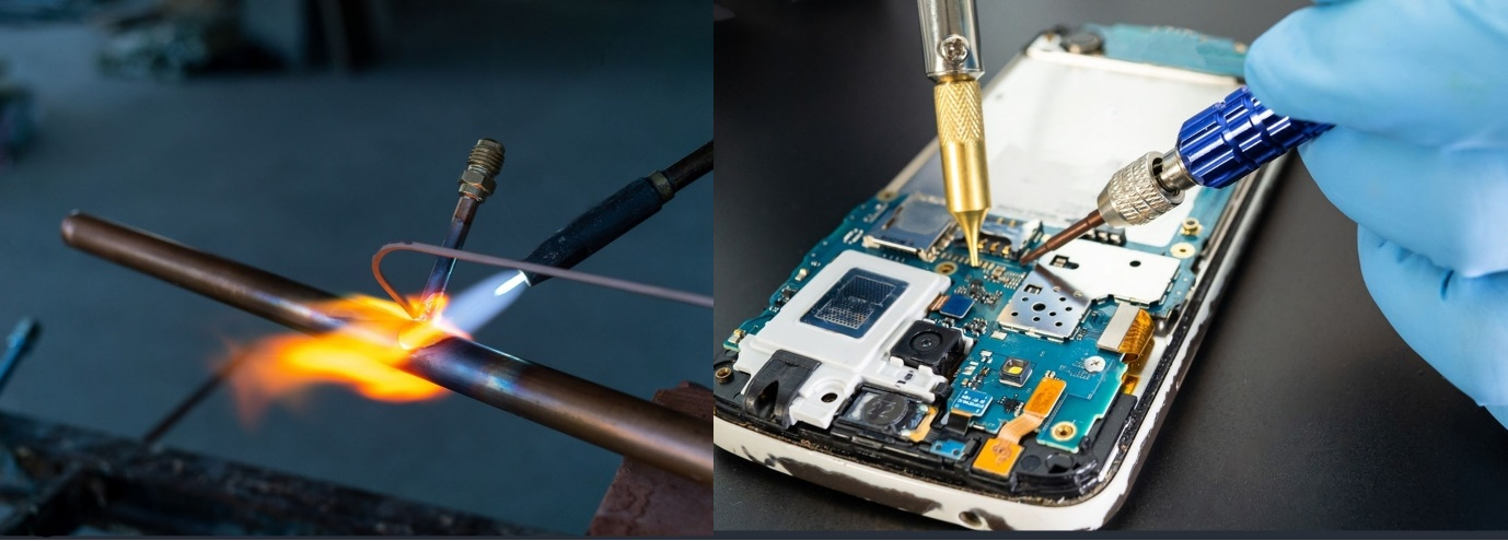
Hand Soldering
Hand soldering is carried out manually using a hot soldering iron. The working end of the iron, known as the bit, is typically made of copper. To extend the lifespan of the copper tip, it is coated with a layer of solder-wettable metal, such as iron, which may have additional coatings. This iron coating dissolves in molten solder much more slowly than copper, and it also resists wear, oxidation, and pitting better than uncoated copper.
Soldering irons can be categorized into four main types to aid in selection: (1) soldering irons for service technicians, (2) transformer-type, low-voltage pencil irons, (3) special quick-heating and plier-type irons, and (4) heavy-duty industrial irons.
One cannot gauge the effectiveness of electrical industrial irons only by looking at the heating element's wattage rating. The heat reserve and temperature recovery of the copper tip are influenced by the iron's construction and materials.
To apply the most heat possible to the job, the angle at which the copper tip is applied is crucial. To get the greatest area of contact, the work should be applied using the flat side of the tip. It is not recommended to melt flux-cored solders on the soldering tip as this would negate the flux's usefulness. To properly commence heat transmission, the cored solder should be contacted to the soldering tip. The solder should then melt on the work components to complete the solder joint.
These days, hand soldering irons come in a variety of tip sizes and are made with carefully regulated temperatures to maintain the necessary soldering temperatures and function with certain solder wire diameters.
Wave Soldering
Using a mechanical process called wave soldering, many lead wires may be soldered to a printed circuit board (PCB) as it is being passed over a wave of hot solder. A common configuration involves loading a PCB onto a conveyor for passage through the wave-soldering apparatus after electrical components have been assembled on it with their lead wires poking through the holes in the board. The PCB is supported on its sides by the conveyor, exposing its underside to the following processing steps: (1) One of various techniques, such as foaming, spraying, or brushing, is used to apply flux; (2) preheating, which involves raising the assembly's temperature, activating the flux, and evaporating solvents using light bulbs, heating coils, and infrared devices; and (3) wave soldering, which forms the solder connections between the lead wires and the metal circuit on the board by pumping liquid solder from a molten bath through a slit onto the board's bottom. The figure below shows how to do this third step.
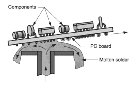
As the drawing shows, the board is frequently somewhat angled, and to reduce the surface tension of the molten solder, a certain tinning oil is added in. The accumulation of surplus solder and the development of "icicles" on the board's bottom are both prevented by these two methods. Wave soldering is a common technique in electronics for producing printed circuit board assemblies.
Reflow Soldering
The assembly of surface mount components onto printed circuit boards is another common usage for this technique in electronics. During the procedure, locations on the board where electrical connections between surface mount components and the copper circuit are to be created are covered with a solder paste comprised of solder powders in a flux binder. Following the placement of the components on the paste places, the board is heated to melt the solder, creating electrical and mechanical linkages between the copper on the circuit board and the component leads. The two types of heating techniques used in reflow soldering are infrared and vapor phase.
In vapor phase reflow soldering, an inert hydrocarbon liquid that has been fluorinated is heated in an oven to evaporate it. The vaporized liquid then condenses on the board surface, where it transfers its heat to melt the solder paste and create solder junctions on printed circuit boards. The heat from an infrared lamp is used in infrared reflow soldering to melt the solder paste and create junctions between component leads and circuit locations on the board. Using hot plates, hot air, and lasers are other heating techniques to reflow the solder paste.
Advantages and Disadvantages of Soldering
Soldering has several benefits, such as (1) low energy input compared to brazing and fusion welding; (2) a range of available heating methods; (3) good electrical and thermal conductivity in the joint; (4) the ability to create liquid- and air-tight seams for containers; and (5) ease of repair and rework. The two main drawbacks of soldering are (1) poor joint strength unless mechanical reinforcement is included, and (2) the junction's potential to degrade or melt when used in high-temperature environments.
References
O'Brien, R.L. (ed.) (1997) Welding Handbook. 8th edn. Vol. 2, Welding Processes. American Welding Society.
Groover, M.P., 2010. Fundamentals of Modern Manufacturing: Materials, Processes, and Systems. 4th ed. Hoboken, NJ: John Wiley & Sons, Inc.