Introduction
The technical drawings of your part are documents that provide very comprehensive two-dimensional representations of the part. These mission-critical drawings make it possible to communicate clearly and completely with the manufacturer about the needs of the product.
Technical drawings are crucial instructions that shed light on 3D models when it comes to CNC machining. We will discuss and go over the many components of technical drawings, and the significance of those components, as well as provide step-by-step directions for producing technical drawings for your products.
What is an engineering drawing for a CNC part?
When beginning a new project involving CNC machining, the way the terminology is expressed will not be clear. As a result, we consider the engineering product specifics and the technical drawings to be the defining standard. In its most basic form, it is a technical document that engineering circles make use of in order to precisely explain the shape, size, and related technical requirements of CNC parts.
A drawing file that is used to represent ideas is called an engineering drawing. However, an engineering drawing also includes a description of the technical requirements and the production process. The engineering notion conceived by the designer has been conveyed accurately. Consequently, drawings can be used to depict material specifications, limits, permissible alterations, and other relevant information. There are many other kinds of drawings, but the STP, DWG, and 3DM formats are the most used ones.
How are CNC part drawings made?
The use of drawing boards, rulers, protractors, calipers, and other similar tools to create what are now referred to as hand-drawn engineering drawings were common in an era when computers were not widely utilized. Using this method to draw typically takes more time and is more likely to result in mistakes. Therefore, as times change, we have entered the era of information drawing in order to draw CNC parts engineering drawings more rapidly and precisely. Because of the development of computer-aided design (CAD) software, things are now simpler.
This program offers a number of benefits over traditional methods of drawing by hand. Is it possible for us to begin completely fresh using CAD? Drawing paper, the creation of a 3D model, followed by adjustments and modifications to the size of the CNC parts based on the 3D model, is one method we may use to provide a more intuitive description of our CNC components. In comparison to CAD applications, 3D models will have an easier time updating and modifying any accompanying drawings.
What Benefits Do Technical Drawings Have for CNC Machining?
Within the realm of CNC machining, 3D CAD files and technical drawings, both of which are essential documents, are used in conjunction with one another. It is impossible to emphasize the significance of these technical documents, which can be seen in the significant roles that they play in the manufacturing process, as seen in the following examples:
Technical drawings are used to describe aspects of a product that cannot be incorporated into a three-dimensional computer-aided design model. The use of both external and internal threads is one example of such a feature.
A full understanding of the requirements for producing the part can be achieved by the manufacturer through the use of dimensions, annotations, and tolerances.
The manufacturer can get instructions from the component's designer and the engineering team on any particular requirements, such as surface roughness and finishing.
What happens if the design you've chosen for your part doesn't call for any complicated features or has any specific requirements? Because the manufacturer will very certainly refer to the technical drawings at some point throughout the manufacturing process, including them with your 3D model is something that we continue to strongly urge you to do.
Why is it still necessary to source parts using technical drawings?
Within the realm of CNC machining, 3D CAD files and technical drawings, both of which are essential documents, are linked together. It is impossible to emphasize the significance of these technical documents, which may be seen in the significant roles that they play in the production process, as shown in the following examples:
Technical drawings are used to describe aspects of a product that are not capable of being incorporated into a 3D CAD model. One example of such a feature is the presence of both external and internal threads.
A complete grasp of the requirements for producing the item can be gained by the manufacturer through consideration of the part's dimensions, annotations, and tolerances.
The manufacturer can get instructions from the component's designer and the engineering team regarding unique needs, such as the surface's roughness and finishing.
What should you do if the design of the part you're making doesn't call for any complicated features or specific requirements? It is still highly recommended that you send technical drawings with your 3D model because we, the manufacturer, will most certainly refer to them during the process of production.
What are the various components of technical drawings?
The following is a list of the various components that are typically included in a technical drawing:
· The title block
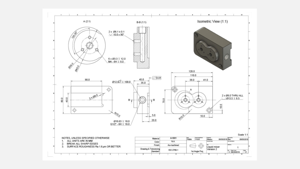
The title block is an essential component of every technical drawing. It contains fundamental information about the part, such as its name, material, finishing, scale, dimensioning, and tolerancing standards, as well as information about the part's designer and/or company. The title block is represented by the red box in the sample drawing shown above. The title block assists manufacturers in understanding the application and purpose of the part that is being given, which then enables them to have a better comprehension of the necessary specifications.
· Isometric view
Because it gives a 3D depiction of the component, the isometric view of the part makes it much simpler for the reader to picture and comprehend the component in a short amount of time. Isometric views are utilized for these reasons as a result of the fact that they combine the illusion of depth with the display of the part's geometry in an undistorted manner (vertical lines remain vertical and horizontal lines are drawn at 30 deg).
· Dimensioned orthogonal views of the part
The primary orthogonal views are representations in two dimensions of the three-dimensional part in greater detail, exactly as they would appear when viewed from the exterior of a bounding box, one side at a time. This is done so that measurements and features may be communicated more clearly, and this drawing style is only applied to the margins of the parts. The primary purpose of these views is to represent all of the component's detailed dimensions, features, and specifications. For example, length, surface roughness, tolerancing ranges, feature descriptions, and so on are all depicted using these views.
For the majority of components, it is possible to envision and produce the complete component by utilizing two or three orthogonal perspectives.
· Section and detailed views of the component
The fundamental internal elements of the part, particularly those features that are obscured in the primary orthogonal and isometric views, can be depicted using section views, which can be utilized to depict the essential internal features of the part. In a primary orthographic view, the location of the part's cross-section is indicated by a cutting line, and in a section view, the cross-hatch pattern highlights areas of the part from which material has been removed. The arrows that are located on the cutting line point in the direction that you are now gazing at. In drawings that have more than one section view, the cutting line can be given a name beginning with an alphabet such as A-A, B-B, etc., so that each section view is associated with the cutting line that corresponds to it. Although section views are typically positioned in line with an orthographic view, they can also be positioned in any other part of the design if necessary. The component can be cut along its entire width, along half of its width, or at an angle, depending on the desired sectioning. An example of a section view is the square in red that can be found at the bottom of the drawing that was presented earlier.
The intricate or difficult-to-dimension portions of a primary orthographic view can be brought into focus with the help of detailed views. They are often in the shape of circles and are offset from one another to prevent misunderstanding. Additionally, they are annotated with a single letter that connects the detail view to the main drawing (for example A, B, and so on).
As long as the scale difference between the rest of the drawing and the detail views is made explicit, the detail views can be positioned anywhere on the drawing and can utilize a different scale than the rest of the drawing.
· Important notes to the manufacturer for fabrication
On the technical drawing, on the bottom left, there is space reserved for adding notes to the manufacturer. These notes can be used to communicate any additional pertinent information that was omitted from the technical drawing. This section can be expanded to include, among other things, directions to break (deburr) all sharp edges, a common fillet radius, general surface polish criteria, or a reference to another component with which the part in the drawing interacts.
Occasionally, symbols will be utilized rather than text. For instance, symbols are typically utilized in the annotation of surface roughness.
How to add critical dimensions to the technical drawings?
The dimensions on the drawings have to be identical to those on the uploaded portion. This makes the process of assessing and quoting much simpler, and it enables us to guarantee that we can thoroughly evaluate your part for any DFM issues if there are any.
The following are the steps that we recommend you do in order to make a good engineering drawing:
- Include the fundamental portion dimensions that will be used to define the value of its boundaries.
- Include the dimensions for any crucial features that are necessary for the component to operate without any hiccups. It might be a slot, it might be a hole, or it might be a dowel pin.
- Now add the remaining dimensions, which are required to be added. It is recommended that dimensions be added against a datum to guarantee that everything is consistent.
- It is appropriate to provide the feature's description when there are many occurrences of the same kind, such as when they are arranged in a pattern; this is done in addition to the total number of occurrences of that particular kind of feature.
Step-by-step process for the technical drawing of CNC Machining
Even though there is no universally applicable method for generating a technical design for CNC machining, the following stages should be adhered to in order to make sure that your drawings are as accurate and detailed as they possibly can be:
- Prioritize the views of your component by placing orthographic views in the middle of the drawing once you've identified the most essential perspectives. When adding dimensions, it is important to ensure that there is sufficient space between the orthographic views.
- Examine your component to determine whether it has any complicated features or other regions that are difficult to dimension. If this is the case, you should provide detailed views or section views.
- Afterward, include construction lines in each of the views. This comprises centerlines, which are used to define planes or axes of symmetry, as well as center marks and center mark patterns, which are used to define the location of the centers of hole patterns or circular patterns.
- After you have added the construction lines to your drawing, the next step is to add the dimensions to your drawing. We recommend beginning with the measurements that are the most important, to begin with.
- Describe in detail where each thread is located, how long it is, and how big it is.
- If any of the features require a higher degree of accuracy than the typical tolerances allow for, add any additional tolerance information that is necessary.
- Fill up the information in the title block, and check that any pertinent notes for the manufacturer section that pertain to special requirements, such as surface finish and deburring instructions, have been added.
What is the process for including threads in a technical drawing?
If the parts you are designing contain threads, then you need to make sure that they are clearly identified and defined on the technical drawing. Instead of defining threads in terms of diameter dimensions, a standard thread size should be used instead. It is recommended that precise thread callouts be provided since they make the drawing more understandable and permit the definition of pilot holes and threads with varying lengths.
It is recommended that the pilot hole's dimensions be defined in the first operation (the proper diameter can be found in standard tables), followed by the thread's dimensions (and tolerance) in the second operation.
How are tolerances indicated on a technical drawing?
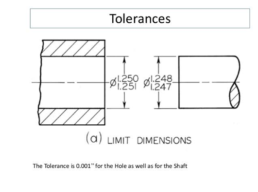
Tolerances specify the allowable variation in a part's dimensions. Particularly crucial are tolerances for features that interact with other parts, as they reveal information about the part's intended use.
Any dimension on a CNC drawing can have a tolerance attached to it, and those tolerances can be written in a variety of ways (both linear or angular).
The most basic tolerance is the bilateral tolerance, which is symmetrical about the fundamental dimension (such as 0.1 mm). Unilateral tolerances (with contrasting upper and lower limits) and engineering fit tolerances are two further types.
Conclusion
In today's world of CNC machining, the manufacturing process typically starts with a 3D CAD model that is developed by specialist software. This model is then used in subsequent steps. The 3D model is converted into G-code, which is a CNC machine language, with the use of computer-aided manufacturing (CAM) software. After the part's programming is complete, the CNC machine will make it through subtractive procedures.
There is no way around the fact that 3D CAD files have a plethora of information that is necessary for CNC machines. In spite of this, the extraordinary usefulness of technical drawings is not diminished by the existence of a 3D CAD file. Technical drawings are the cornerstone of communicating designs to manufacturers, and this fact will not change in order to guarantee that your product will be manufactured exactly as you planned.