

In CNC machining, precision is more than a technical goal; it is the foundation of product quality. Every part, whether a simple bracket or a complex aerospace component, must meet dimensional and geometric requirements to function as intended. This is where tolerances and Geometric Dimensioning & Tolerancing (GD&T) come in. Together, they define the allowable variation in size, shape, and position, ensuring that machined parts fit, perform, and last as expected.
Tolerances alone safeguard dimensions, but they don’t always capture the full story. Two parts might share the same nominal size yet fail to assemble if their flatness, concentricity, or parallelism is not controlled. GD&T extends beyond basic dimensions, using a system of symbols and rules to describe form, orientation, and location in a clear, standardized way. This reduces ambiguity between design intent, machining execution, and inspection results.

Maintaining accuracy is not just about avoiding scrap; it directly affects assembly reliability, performance efficiency, and product lifespan. From automotive engines to surgical tools, overlooked tolerances can mean vibration, leaks, or catastrophic failure. This article explores why tolerances and GD&T are critical in CNC machining, showing how they bridge the gap between design and production while setting the stage for consistent, high-quality manufacturing outcomes.
The Real Role of Tolerances in CNC Quality
Every machined part exists within a balance of precision and practicality. While designers often imagine an “ideal” size, machinists know perfection does not exist at scale. Cutting tools wear, machines expand with heat, and even stable setups show slight variations. Tolerances are the framework that defines what degree of imperfection is acceptable. Without them, manufacturing becomes guesswork, and assemblies either fail or become unnecessarily expensive to produce.
What Are Tolerances?
Tolerances are best understood as limits. They create a safe window around a target dimension, allowing parts to vary slightly while still being functional. This concept bridges the gap between theoretical design intent and real-world manufacturing conditions.
When applied correctly, tolerances ensure:
- Interchangeability: Multiple suppliers can make the same part and still guarantee compatibility.
- Predictability: Assemblies behave as expected, even if parts are not mathematically perfect.
- Efficiency: Manufacturers avoid chasing “zero-error” results that add no practical value.
Dimensional vs. Geometric Tolerances
- Dimensional tolerances control size. For instance, a shaft might be allowed ±0.02 mm variation in diameter.
- Geometric tolerances control shape, orientation, and position. Even if two shafts are the same size, their usability differs if one is bent or off-center.
Both must be considered together. Size without shape is meaningless, and geometry without dimension leaves gaps in functional performance.
Loose vs. Tight Tolerances
Not every feature demands microns of accuracy. Some parts perform perfectly with wider limits, while others fail catastrophically if they deviate by even a fraction. Choosing between loose and tight tolerances is both an engineering and an economic decision.
Loose Tolerances
These are generally assigned to non-critical features.
- Easier to achieve with standard tools and machines.
- Faster production cycles, reducing cost.
- Often applied to brackets, guards, or covers where aesthetics matter more than precision.
Tight Tolerances
These are reserved for features where the function depends on exactness.
- Require precision machines, thermal control, and sometimes multiple finishing passes.
- Increase tooling wear and inspection costs.
- Essential for high-stress fits, sealing surfaces, and moving assemblies.
Example: Consider an engine piston pin. Even a 0.01 mm deviation may cause binding or excessive clearance, leading to rapid wear. In contrast, the engine’s external cover plate can be manufactured with a much looser tolerance without affecting performance.
Why Tolerances Matter
The role of tolerances extends beyond individual features; they influence entire assemblies and the long-term reliability of machines. Poor tolerance management often reveals itself not during machining, but during operation.
Impact on Assembly Fit
- Clearance fit: Allows parts to slide easily. Too much clearance can cause vibration.
- Interference fit: Holds parts tightly. If tolerances are off, assembly becomes impossible.
- Transition fit: Balances between clearance and interference. Precision here is critical.
Influence on Performance
- Bearings require precise bores to prevent spinning or loosening.
- Shafts need tight control to reduce imbalance and vibration.
- Gear teeth rely on controlled spacing to avoid noise and premature wear.
Reliability and Longevity
Overly loose tolerances may seem harmless at first, but they often lead to long-term failures. Looseness translates into misalignment, heat generation, and unexpected breakdowns. Conversely, overly tight tolerances may cause excessive friction or assembly damage. Both extremes erode confidence in the final product.
The Cost of Poor Tolerance Control
Ignoring tolerance discipline is one of the most expensive mistakes in CNC production. Problems may not show up immediately, but the downstream costs are significant.
- Rework and scrap: Parts falling outside tolerance must be corrected or discarded.
- Assembly delays: Misaligned fits slow production lines and increase labor costs.
- Field failures: Warranty claims, recalls, and loss of customer trust often trace back to tolerance errors.
Case in point: A manufacturer producing hydraulic valves once saved cost by relaxing bore tolerances. Within months, customer complaints spiked due to internal leakage. The rework, replacements, and reputational damage far outweighed the savings.
Tolerances as Risk Management
Ultimately, tolerances are not about perfection; they are about reducing uncertainty. By defining achievable and functional limits, they:
- Protect design intent from being lost in translation.
- Give machinists a clear target window for production.
- Provide inspectors with measurable criteria for acceptance.
Good tolerance practices ensure that even with natural variation, parts will perform reliably. This is why the tolerance definition is one of the first steps in transforming a design into a manufacturable, dependable product.
Introduction to Geometric Dimensioning & Tolerancing (GD&T)
Dimensional tolerances alone cannot ensure a part will function correctly. Two features may meet size requirements but fail when their orientation, alignment, or form is uncontrolled. Geometric Dimensioning & Tolerancing (GD&T) closes this gap by offering a common, symbol-based language that describes not just how big a feature should be, but how it should relate to other features in space.
What Is GD&T?
GD&T defines acceptable geometric variation, ensuring that parts not only measure correctly but also assemble and operate as intended. It creates tolerance “zones” where features are allowed to exist, giving manufacturers flexibility while preserving functional requirements.
This concept is critical in industries where even a small misalignment can lead to performance failure. For example, in jet engines, a shaft only slightly off-axis can introduce vibration strong enough to damage bearings. Dimensional tolerances alone cannot prevent this; GD&T controls like concentricity and runout are required.
Historical Context
GD&T was born out of necessity in high-stakes industries. During World War II, mass production of parts across multiple factories revealed that size-based tolerances were not enough for assembly consistency. The push for a universal standard led to ASME Y14.5 in the U.S. and ISO equivalents in Europe, paving the way for global adoption.
Geometric Dimensioning And Tolerancing (GD&T)
Today, GD&T is no longer limited to aerospace or defense; it is equally vital in automotive, medical, robotics, and consumer electronics, where precision at scale determines competitiveness.
Key GD&T Symbols and Concepts
Each GD&T symbol is more than a shorthand; it represents a real-world condition that directly affects performance.
Form Controls: Ensuring Shape Accuracy
- Straightness: A CNC-machined shaft may meet size tolerance but still be slightly bent. Straightness ensures the shaft runs true in bearings.
- Flatness: A sealing surface on a hydraulic valve must be flat; otherwise, leaks occur even if size tolerances are correct.
- Circularity: A bearing bore must be round, not oval, to prevent uneven load distribution.
Orientation Controls: Defining Alignment
- Perpendicularity: Critical for gearboxes, where shafts must intersect at right angles for proper meshing.
- Parallelism: Used in sliding components like guide rails to ensure smooth, low-friction movement.
- Angularity: Ensures parts designed at non-90° angles, such as turbine blades, maintain correct orientation for airflow efficiency.
Location and Runout: Controlling Position and Motion
- Position: Ensures holes in a flange align with mating parts. Even if the size is correct, a poor location prevents assembly.
- Concentricity: Keeps rotating shafts aligned with their bores, reducing imbalance.
- Runout: Vital in rotating machinery, controls wobble in parts like brake discs or spindle assemblies.
Datums: The Reference System
Think of datums as the "anchor points" for measurement. A datum might be a flat mounting surface, a hole pattern, or a center axis. They establish a consistent reference so that every machinist and inspector checks a part against the same baseline.
Without datums, tolerance interpretation becomes subjective, leading to inconsistent production.
Advantages of GD&T Over Standard Dimensions
The main advantage of GD&T is that it communicates function, not just size. Traditional dimensions may pass inspection but fail in assembly; GD&T ensures that what is measured reflects how the part will actually perform.
Clearer Communication Across Teams
- Designers capture intent more fully.
- Machinists understand what must be controlled tightly and what has flexibility.
- Inspectors measure features against functional requirements, not vague interpretations.
Prioritization of Critical Features
GD&T avoids over-constraining parts. Instead of demanding tight tolerances everywhere, it highlights what really matters, reducing machining costs while still ensuring functionality.
Example: A medical implant may require ultra-tight control on mating surfaces that contact bone or screws, but outer contours that affect only aesthetics can be manufactured with looser limits.
Bonus Tolerance: Built-In Flexibility
A unique feature of GD&T is bonus tolerance. For example, if a hole is allowed a positional tolerance of 0.1 mm at maximum material condition (MMC), then if the hole is drilled slightly larger than the MMC limit, extra tolerance is automatically allowed. This creates manufacturing flexibility without compromising assembly fit.
Case Studies: GD&T in Action
Aerospace Turbine Blades
Jet engines demand extreme precision. A turbine blade must maintain angularity and parallelism to channel airflow efficiently. If blades deviate even slightly, fuel efficiency drops and vibrations increase. Here, GD&T angularity and profile controls ensure consistent performance across thousands of blades.
Automotive Engine Blocks
Engine blocks contain numerous bores and threaded holes. Dimensional tolerances alone cannot guarantee that crankshaft and camshaft bores will align perfectly. GD&T position and concentricity controls ensure proper alignment, reducing vibration and improving engine life.
Medical Devices
Surgical tools like orthopedic drills require concentricity between shafts and cutting tips. Even a minor misalignment can compromise accuracy in surgery. GD&T ensures geometric control so tools remain safe and precise.
GD&T as a CNC Machinist’s Tool
For machinists, GD&T is not just a design concept; it directly informs setup and execution.
- Datums guide how parts are fixtured on machines.
- Toolpaths are adjusted to maintain perpendicularity or parallelism.
- Inspection programs for CMMs are written to measure GD&T zones, not just dimensions.
When embraced as a daily practice, GD&T shifts machining from “making parts to size” toward “making parts to function.” That distinction is what separates high-quality CNC manufacturing from basic cutting operations.
Real-World Applications of GD&T and Tolerances
Tolerances and GD&T are not abstract engineering exercises; they are the backbone of functional, reliable products. A perfectly modeled design in CAD means little unless the physical part can be machined and assembled with predictable accuracy. In practice, tolerances dictate whether components fit smoothly, whether assemblies last years instead of months, and whether machines perform consistently under demanding conditions. This section explores how tolerances and GD&T influence assembly, performance, and industry-specific applications.

Geometric Dimensioning & Tolerancing (GD&T)
Assembly Fit and Function
The most immediate impact of tolerances and GD&T is on assembly. Even simple products often involve dozens of parts, each with its own variation. When these variations combine, they create what’s known as tolerance stack-up.
Tolerance Stack-Up in Practice
Imagine a gearbox housing with five aligned bores for shafts. If each bore deviates by just 0.02 mm, the cumulative misalignment can exceed 0.1 mm, enough to prevent assembly or cause binding. GD&T helps by controlling these relationships, using position tolerances and datums to anchor critical features.
Types of Fits
- Clearance fit: Provides space between mating parts. Common in sliding assemblies like drawer rails or guide shafts.
- Transition fit: Balances slight clearance and interference. Often used in couplings.
- Interference fit: Requires press assembly. Typical in bearing seats or dowel pins.
Without tolerances, a clearance fit may become too loose, leading to vibration, or too tight, making assembly impossible.
Example: Automotive wheel hubs rely on controlled interference fits for bearings. Too loose, and bearings spin inside the hub. Too tight, and they seize during installation.
Performance and Longevity
Tolerances and GD&T do more than ensure parts fit together; they safeguard performance over the product’s lifespan.
Vibration and Noise Reduction
- Tight runout control on rotating parts reduces imbalance.
- Proper parallelism ensures gear teeth engage evenly, minimizing noise.
Wear and Efficiency
- Straight shafts prevent uneven bearing wear.
- Flat sealing surfaces prevent fluid leaks in hydraulic systems.
Example: In aerospace, turbine shafts demand strict concentricity. A minor offset creates an imbalance, increasing wear rates and reducing engine efficiency. Even a 0.05 mm error at high rotational speeds can have catastrophic results.
Avoiding Early Failures
When tolerances are poorly defined or controlled:
- Bolted assemblies may loosen due to uneven load distribution.
- Misaligned holes cause stress concentrations, leading to cracks.
- Pump impellers with excessive runout cause cavitation and early breakdown.
By enforcing GD&T, these issues are identified at the drawing stage and prevented on the shop floor.
Industry Examples
Different industries highlight how tolerances and GD&T adapt to specific performance needs.
Automotive Industry
- Engine Blocks: Position and perpendicularity tolerances ensure crankshaft bores align correctly, preventing vibration.
- Transmission Gears: Circularity and parallelism tolerances ensure gears mesh quietly and efficiently.
- Brake Discs: Runout tolerances prevent brake judder, improving driver safety.
Aerospace Industry
- Airframe Assembly: Thousands of rivet holes across multiple panels must align. Position tolerances ensure interchangeability of components produced in different facilities.
- Jet Turbines: Angularity and concentricity tolerances keep turbine blades aligned, maximizing thrust and fuel efficiency.
- Landing Gear: Cylindrical tolerances maintain alignment between struts and actuators, critical for safe operation under load.
Medical Devices
- Implants: Orthopedic screws and plates require precise thread tolerances to ensure compatibility with surgical tools.
- Surgical Instruments: Concentricity tolerances on rotating drill bits prevent wobble during operations.
- Prosthetics: Parallelism ensures joint replacements move smoothly without premature wear.
Electronics and Robotics
- Connector Housings: Position tolerances guarantee pin alignment, preventing signal loss.
- Precision Robots: Straightness and flatness tolerances ensure guide rails allow repeatable micron-level positioning.
- Consumer Electronics: Smartphone housings use tight flatness and profile tolerances to ensure seamless fit of displays and batteries.
Lessons from Tolerance Failures
Real-world failures often highlight the importance of proper tolerance management.
- Automotive Recall: A major car manufacturer faced a recall due to vibration caused by excessive runout in drive shafts. The issue was traced back to unclear GD&T on supplier drawings.
- Medical Device Failure: An orthopedic implant failed because the screw holes were not properly located. Though within dimensional tolerance, their position tolerance was missing, leading to misalignment during surgery.
- Aerospace Incident: Misaligned turbine blades in a regional jet caused premature fatigue, grounding the aircraft for weeks. The root cause: tolerance stack-up was overlooked during design.
These cases underline the cost of neglecting GD&T, not just in rework or warranty claims, but in safety, brand trust, and regulatory consequences.
CNC Inspection and Tolerance Verification
Defining tolerances and GD&T on a drawing is only the beginning. The real test comes on the shop floor: verifying that machined parts conform to specifications. CNC inspection bridges the gap between design intent and physical reality, ensuring deviations are detected early and quality is maintained throughout production. Without robust inspection, even the best-designed tolerances are meaningless, as errors can slip through and compromise entire assemblies.
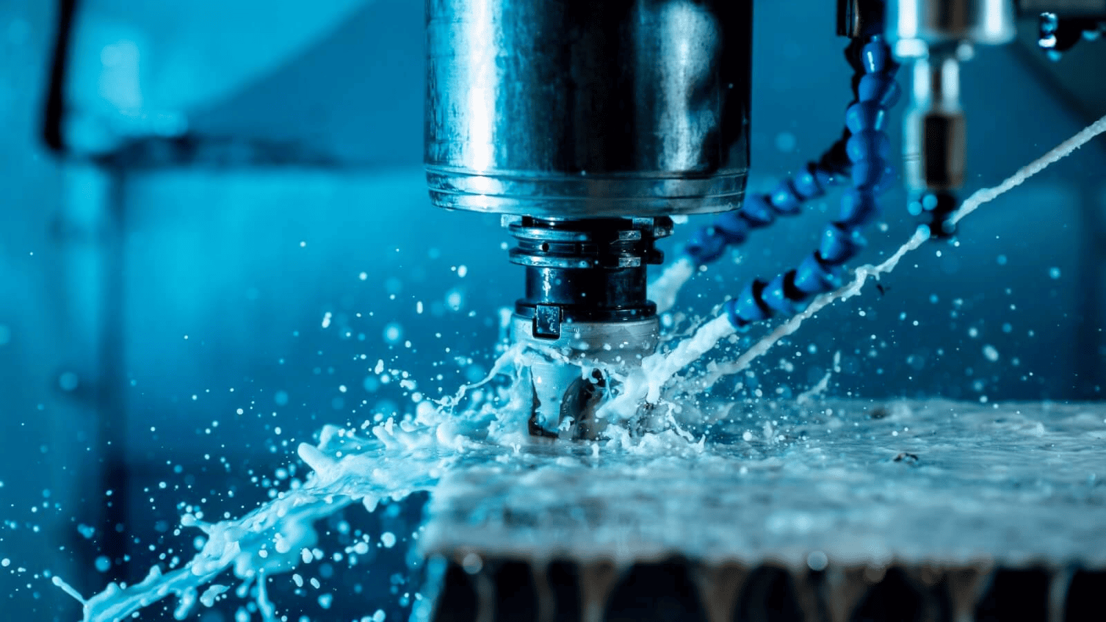
Achieve Tighter CNC Machining Tolerances
Methods of Inspection
Inspection methods range from simple manual tools to advanced, automated systems. Each has its place depending on tolerance requirements, production volume, and cost considerations.
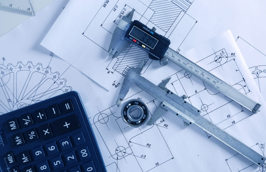
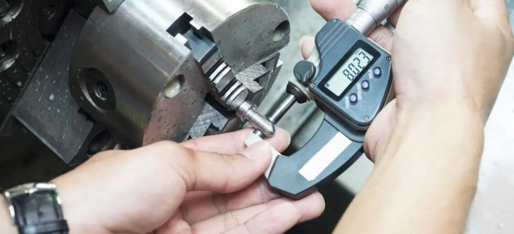
Traditional Measurement Tools
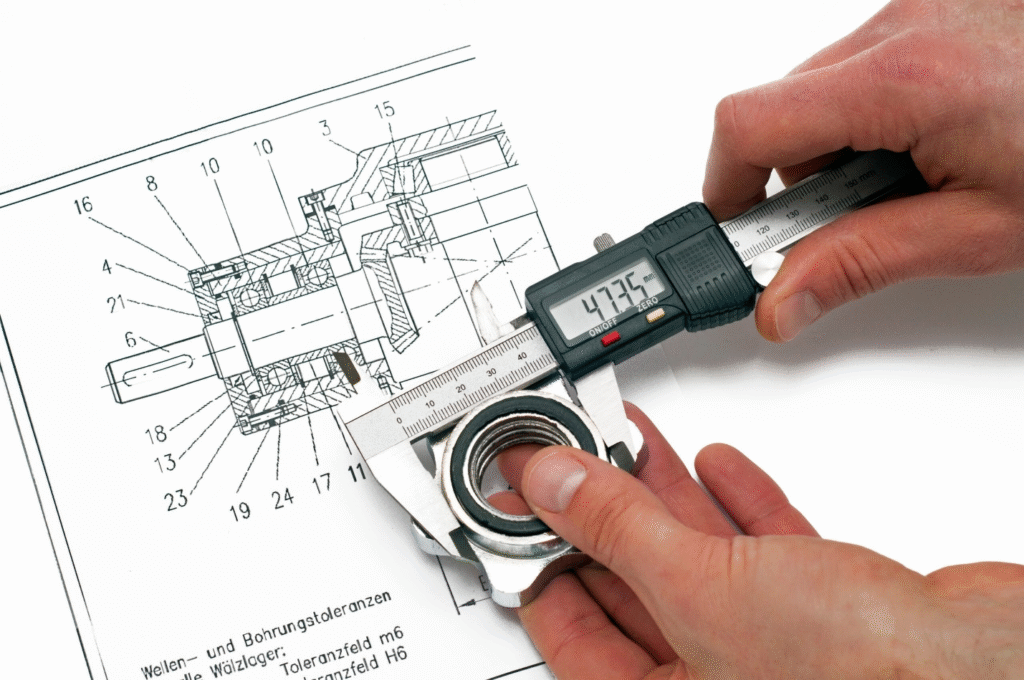
- Micrometers and Calipers: Quick and effective for checking dimensions like lengths, diameters, and thickness. Ideal for loose-to-moderate tolerances.
- Height Gauges and Surface Plates: Provide reference-based checks for flatness, parallelism, or simple alignment tasks.
- Go/No-Go Gauges: Verify whether a feature falls within tolerance limits without giving exact measurement values.
While cost-effective, these methods rely heavily on operator skill and are less suitable for extremely tight tolerances.
Inspection and Quality Control in Machining
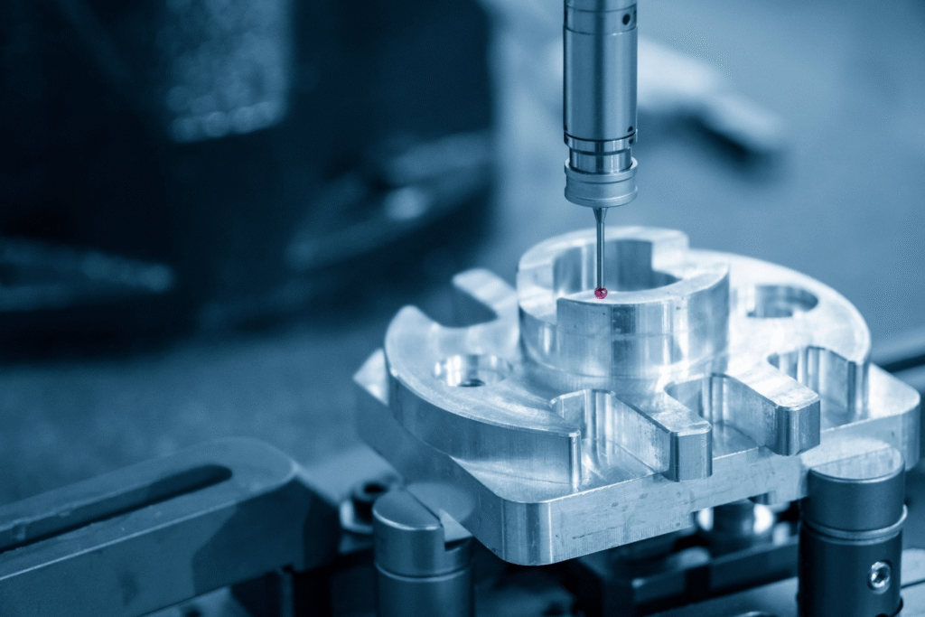
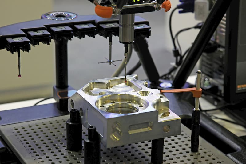
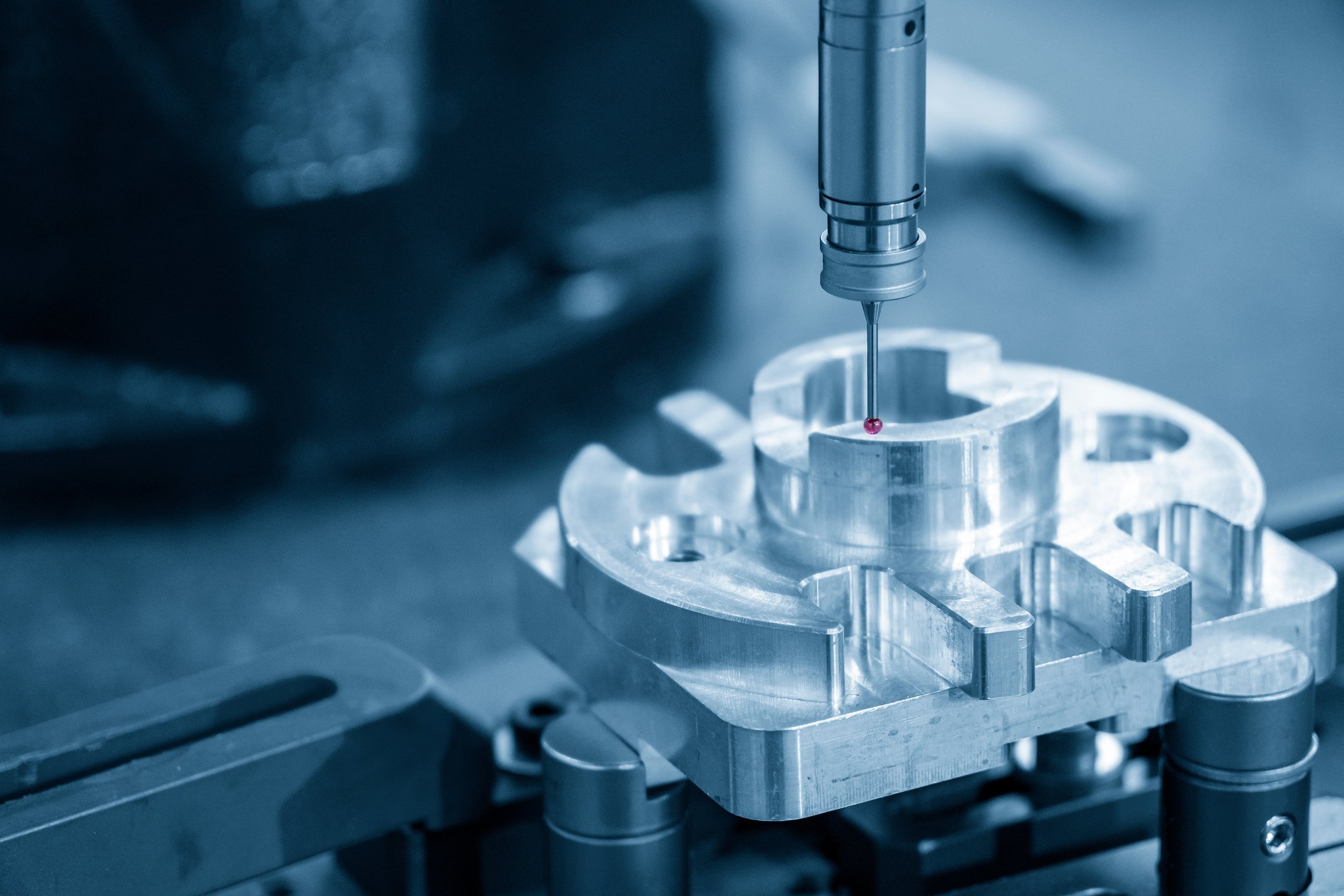
Coordinate Measuring Machines (CMMs)
CMMs revolutionized inspection by allowing precise 3D measurements. A probe moves along X, Y, and Z axes to capture data points, verifying both dimensional and geometric tolerances.
- Advantages: High accuracy, ability to check complex geometries, automated reporting.
- Applications: Ideal for aerospace engine components, medical implants, and automotive engine parts where micron-level precision is required.
Non-Contact Inspection
- Laser Scanning: Captures millions of data points quickly, useful for freeform surfaces and reverse engineering.
- Optical Measurement Systems: Cameras and light patterns verify features without touching the part, which is valuable for delicate or very small components.
Example: Smartphone housings are often inspected with optical systems to confirm flatness and profile tolerances without risking scratches.
Inline vs. Offline Inspection
- Offline Inspection: Parts are removed from production and inspected separately. Offers high precision but can cause delays.
- Inline Inspection: Measurement integrated directly into the machining cell. Sensors and probes check parts in real time, reducing the risk of producing large batches of defective parts.
Ensuring Tolerance Integrity
Inspection is not just about pass/fail decisions. It is an ongoing process that safeguards tolerance integrity across the production cycle.
Catching Deviations Early
By checking parts at multiple stages, raw machining, semi-finished, and final, manufacturers prevent errors from propagating. This layered approach reduces rework and ensures problems are corrected before mass production.
Example: In automotive assembly lines, bore diameters for cylinder heads are checked after rough machining and again after finishing. Detecting drift early prevents entire batches from being scrapped.
Statistical Process Control (SPC)
SPC uses statistical methods to monitor machining variation. Instead of inspecting every part, a representative sample is measured, and trends are analyzed.
- Cp and Cpk indices indicate whether a process is capable of consistently meeting tolerance limits.
- Control charts detect gradual tool wear, thermal drift, or misalignment before parts go out of tolerance.
SPC transforms inspection from reactive correction into proactive quality control.
Measurement System Analysis (MSA)
Even inspection systems must be verified. MSA evaluates whether measuring equipment and operators produce consistent, repeatable, and reproducible results. Without this step, “bad data” can create false confidence.
Benefits of Inspection in Production
Inspection is often viewed as a checkpoint at the end of machining, but its real value is far greater. It safeguards tolerance integrity, prevents costly rework, and builds customer confidence. The benefits extend across technical, financial, and strategic dimensions of manufacturing.

Conducting a Production Inspection to Ensure Product Quality
Reduced Scrap and Rework
Scrap and rework are among the biggest hidden costs in CNC machining. Each defective part wastes raw material, machine time, tooling life, and operator labor. When inspection catches deviations early, manufacturers minimize these losses.
- In-process probing: Modern CNCs can measure features mid-cycle, allowing tool offsets to be corrected automatically. This reduces scrap from tool wear or thermal growth.
- First Article Inspection (FAI): Verifying the very first piece of a batch ensures that mistakes are detected before hundreds of parts are produced.
Example: An automotive supplier producing engine pistons introduced in-process inspection. Scrap rates fell by 40%, saving both material costs and downtime.
Reliable Assembly and Functional Performance
Inspection ensures that every component entering assembly meets its tolerance requirements. This consistency prevents bottlenecks, reduces manual fitting, and ensures products operate as designed.
- Dimensional accuracy: Ensures shafts fit into bearings, gears mesh correctly, and fasteners align with holes.
- Geometric accuracy: Maintains flatness, perpendicularity, and concentricity so parts align and move without excess friction.
Case Example: A medical device company producing surgical drills enforced stricter CMM inspections for concentricity. This prevented wobble in drill bits, directly improving surgical precision and patient safety.
Compliance with Standards and Certifications
Quality management systems require documented proof that products meet specifications. Inspection provides this evidence. Without it, manufacturers risk losing certifications and market access.
- ISO 9001: Requires documented quality control procedures.
- AS9100 (aerospace): Mandates traceability and inspection reports for every critical part.
- FDA regulations (medical): Demand inspection documentation to prove device safety and reliability.
Example: A supplier of aerospace fasteners maintains detailed inspection reports for every lot. These records not only meet AS9100 requirements but also act as insurance in case of field failures or investigations.
Enhanced Process Control and Continuous Improvement
Inspection data is not just about accepting or rejecting parts; it provides feedback for process optimization.
- Trend monitoring: SPC charts highlight tool wear, thermal drift, or misalignment.
- Predictive corrections: Data helps operators make proactive adjustments, reducing downtime.
- Process improvement: Long-term data trends reveal where tolerances are consistently difficult to meet, guiding design or machining strategy changes.
Case Example: A manufacturer of precision robotics components used inspection data to discover that thermal expansion during afternoon shifts caused bore diameters to drift. Adding temperature control to the workshop stabilized tolerances and eliminated recurring failures.
Customer Trust and Reputation
In industries like aerospace and medical devices, reputation is built on delivering consistent quality. Customers often judge suppliers not only on price but on their ability to prove conformance. Inspection plays a central role in that trust.
- Proof of quality: Detailed inspection reports reassure clients that parts meet exact requirements.
- Fewer disputes: Clear measurement records reduce arguments over responsibility when issues arise.
- Long-term relationships: Reliable inspection practices position a manufacturer as a preferred supplier.
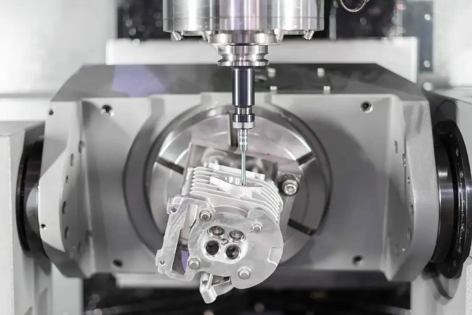
Example: An aerospace machining firm that invested in 5-axis CMMs won additional contracts because its clients valued the inspection data as much as the parts themselves. The firm’s reputation for “quality without question” became a competitive advantage.
Risk Reduction and Cost Avoidance
Perhaps the most overlooked benefit of inspection is risk mitigation. A defective part in the field costs exponentially more than catching it during production.
- Warranty claims: Inspection prevents defective products from reaching customers.
- Recalls: Avoids catastrophic recalls that damage both finances and brand.
- Safety incidents: Prevent failures that could result in injury, lawsuits, or regulatory penalties.
Case Example: A brake disc manufacturer failed to control runout in production. Customer complaints forced a recall of 50,000 vehicles, costing millions. After implementing inline inspection, the company virtually eliminated defective shipments.
Best Practices for Managing Tolerances in CNC Machining
Defining tolerances and applying GD&T correctly is only part of the quality equation. To consistently deliver precision parts, manufacturers need disciplined strategies that integrate design, machining, and inspection. Best practices ensure that tolerances are not just achievable but also economically sustainable, avoiding both over-engineering and under-specification.
Design Considerations
The foundation of tolerance management begins at the design stage. Many manufacturing issues stem from drawings that demand levels of precision unnecessary for the part’s function.
Specify Realistic Tolerances
Overly tight tolerances increase cost and lead time without improving performance if they don’t serve a functional purpose. Designers should:
- Focus on tight tolerances only on critical features such as bearing seats, sealing surfaces, or alignment bores.
- Use looser tolerances for non-functional features like external surfaces or cosmetic areas.
- Apply GD&T selectively to highlight what truly matters.
Example: In an aerospace housing, hole locations for mounting bolts may demand positional tolerances of ±0.02 mm, while outer profile dimensions can tolerate ±0.5 mm without impacting performance.
Collaborate with Manufacturing Teams
Cross-functional collaboration between design engineers and machinists prevents unrealistic specifications. Machinists can advise on what is feasible within available machine capability, while designers can clarify which features are performance-critical.
Case in point: A medical device design team initially specified ±0.005 mm tolerances on all holes. After consultation with machinists, they relaxed most to ±0.05 mm, keeping the ultra-tight limits only where bone screw alignment required them. The result was faster, lower-cost production with no loss of performance.
Machining Strategies
Even the best-designed tolerances will fail if machining processes are poorly managed. Precision comes not just from advanced equipment but also from disciplined process planning.
Tool Selection and Maintenance
- Sharp, rigid tools minimize deflection, essential for tight tolerances.
- Carbide and coated tools extend life in hard materials, reducing drift.
- Regular tool calibration ensures offsets remain correct.
Machine Calibration and Environment
- CNC machines must be routinely calibrated to maintain accuracy.
- Temperature control in the workshop reduces thermal expansion, which can cause dimensional drift.
- Vibration isolation improves repeatability for micro-tolerance parts.
Example: A robotics manufacturer installed climate control around high-precision CNC cells. Dimensional variation dropped by 30%, improving consistency on small, delicate components.
Process Planning
- Multiple finishing passes help achieve tight dimensional and surface tolerances.
- Fixturing strategy must align with the datums defined in GD&T to avoid measurement misalignment.
- In-process probing detects errors early, allowing immediate correction.
Case Example: An automotive supplier introduced in-process probing to verify bore positions mid-cycle. This reduced scrap by catching tool wear before it caused misaligned holes.
Avoid Over-Tightening Tolerances
A common mistake is to default to extremely tight tolerances everywhere. This creates bottlenecks and unnecessary costs. Best practice is to align tolerances with function and capability, only tightening where performance depends on it.
Inspection and Feedback Loops
Inspection should not be the last step in the process, but an integrated element of production. A closed-loop system ensures continual improvement.
Early and Ongoing Inspection
- Perform First Article Inspection (FAI) to validate the process before full production.
- Use in-process inspection with probing or vision systems to catch deviations in real time.
- Carry out final inspection to certify compliance before shipment.
Data-Driven Improvement
Inspection data should feed back into both design and machining strategies.
- SPC trends reveal when tolerances are difficult to maintain, guiding future design adjustments.
- Measurement data helps refine machining parameters, such as feed rates or cutting strategies.
Example: A precision aerospace shop used CMM data to identify consistent out-of-tolerance issues on certain bores. By adjusting fixturing to better align with design datums, they eliminated recurring deviations.
Digital Integration
Modern best practice involves integrating inspection data into a digital quality management system (QMS). This provides:
- Traceability of every part produced.
- Automatic reporting for certifications like ISO or AS9100.
- Real-time dashboards to monitor process capability.
Case in point: A medical implant manufacturer connected inline inspection to their ERP system. Engineers could track tolerance trends in real time, making adjustments before problems escalated.
Common Mistakes to Avoid
Even with good design and machining strategies, certain recurring mistakes undermine tolerance control. Recognizing and preventing these pitfalls is essential for consistent quality.
- Over-Specifying Tolerances: Designers often default to extremely tight tolerances everywhere. This drives up costs, increases scrap, and clogs inspection resources without improving function.
- Ignoring GD&T Datums: Failing to define or properly use datums leads to inconsistent setups and measurement ambiguity. Features may pass dimensional checks but fail in assembly.
- Skipping Early Inspection: Waiting until final inspection to check tolerances allows entire batches of defective parts to accumulate, resulting in costly scrap or rework.
- Neglecting Environment and Calibration: Temperature fluctuations, tool wear, and machine misalignment gradually push parts out of tolerance. Without proactive control, these small errors accumulate.
- Poor Communication Between Teams: Disconnects between designers, machinists, and inspectors lead to mismatched expectations. Drawings may specify what cannot be realistically produced, or machinists may misinterpret critical requirements.
By avoiding these mistakes, manufacturers not only save costs but also ensure tolerances and GD&T serve their real purpose, functional, reliable products.
Conclusion
Tolerances and GD&T are not abstract design details; they are the foundation of reliable CNC machining. Tolerances define the acceptable range of variation, while GD&T ensures geometric accuracy, orientation, and functional relationships between features. Together, they bridge the gap between design intent and manufacturable reality, making sure parts not only meet size requirements but also assemble and perform as expected.
Their importance becomes clear in practice: tolerances safeguard assembly fit, minimize vibration, and extend product life, while GD&T eliminates ambiguity by standardizing communication across design, machining, and inspection teams. From aerospace turbine blades to automotive engine blocks and medical implants, real-world case studies show that even small deviations can cause costly failures when tolerance control is neglected. Inspection and verification provide the safeguard, ensuring that defined tolerances are consistently achieved and maintained through production.
Ultimately, precision in CNC machining is about balance, setting tolerances tight enough to guarantee performance, but not so tight that costs spiral unnecessarily. Best practices, including cross-team collaboration, smart machining strategies, and data-driven inspection loops, ensure this balance is achieved.

