

CNC machining is built on precision. Every component, from the spindle bearings to the cutter tip, must move in perfect harmony to achieve micron-level accuracy. When vibrations enter this system, that harmony breaks. Even a small oscillation between the tool and the workpiece can distort surface finish, reduce dimensional accuracy, and accelerate tool wear. For industries like aerospace, medical, and mold manufacturing, where every cut counts, vibration control is not optional. It is essential.

In machining, vibrations are the repetitive motions caused by dynamic forces acting between the tool, spindle, and workpiece. These vibrations can be mechanical or cutting-induced. When they intensify and become self-sustaining, they turn into chatter, a destructive form of vibration that damages both the part and the tool. Chatter produces visible waves or marks on the surface, leaves a high-pitched noise, and drastically reduces tool life. It also affects the accuracy of subsequent passes because the machine structure and tool lose their stability.
This article explores vibration control in CNC machining through a practical and analytical lens. It identifies the common sources of vibration, explains their impact on machining quality, and outlines methods to minimize them. From optimizing tool overhang to using damping tool holders and advanced feedback systems, we will examine proven strategies that ensure precision and stability. By understanding and controlling vibration, machinists can achieve smoother finishes, longer tool life, and more consistent production outcomes.
Understanding Vibration in CNC Machining
Vibration in CNC machining refers to unwanted oscillations occurring between the cutting tool and the workpiece during material removal. These oscillations arise from dynamic interactions between the cutting forces, the machine structure, and the workpiece stiffness. While minor vibrations are common and often tolerable, excessive vibrations can lead to serious machining defects. To control them effectively, it is essential to understand their nature, sources, and behaviors under different cutting conditions.
What is Vibration and Chatter
Vibration is the repetitive motion that occurs when the tool or workpiece deviates from its intended path due to dynamic forces. In machining, two main forms are observed:
- Forced vibrations: These are caused by external periodic forces, such as unbalanced rotating components, gear meshing, or fluctuating cutting loads. Their frequency is determined by the source of disturbance.
- Self-excited vibrations (chatter): These arise when the cutting process itself feeds energy back into the system, creating oscillations that grow over time. Chatter can quickly become unstable and destructive.

Chatter Vibration in CNC Milling
Chatter is particularly harmful because it amplifies itself. Once initiated, the vibration changes the cutting thickness in each tool pass, reinforcing further vibrations. This feedback loop continues until the system becomes unstable, resulting in poor surface finish, increased tool wear, and even machine damage.
Difference Between Forced and Self-Excited Vibrations
The distinction between these two types of vibrations lies in their energy source and frequency behavior:
- Forced vibrations are externally driven. They often occur at predictable frequencies and can be reduced by improving machine balance, tightening components, or isolating vibration sources.
- Self-excited vibrations (chatter) are internally driven by the cutting action. They depend on cutting parameters such as speed, feed, and depth of cut. Because chatter originates from feedback between the tool and workpiece, it is harder to predict and requires careful parameter tuning or damping to control.
In practice, forced vibrations tend to produce consistent patterns, while chatter generates irregular marks and audible noise. Recognizing this difference helps operators choose the right corrective measures.
Symptoms of Machining Vibrations
Excessive vibration can appear in multiple forms during machining. The most common indicators include:
- Poor surface finish or visible waviness on the part
- Distinct tool marks or chatter marks on machined surfaces
- Sudden noise or tonal resonance during cutting
- Dimensional inaccuracies or roundness errors
- Rapid tool wear or premature tool failure
- Increased spindle load or fluctuating cutting forces
These symptoms may appear individually or together, depending on the process type and machine configuration.
Examples from Common Machining Operations
Vibration behavior differs across machining processes due to tool geometry and cutting mechanics:
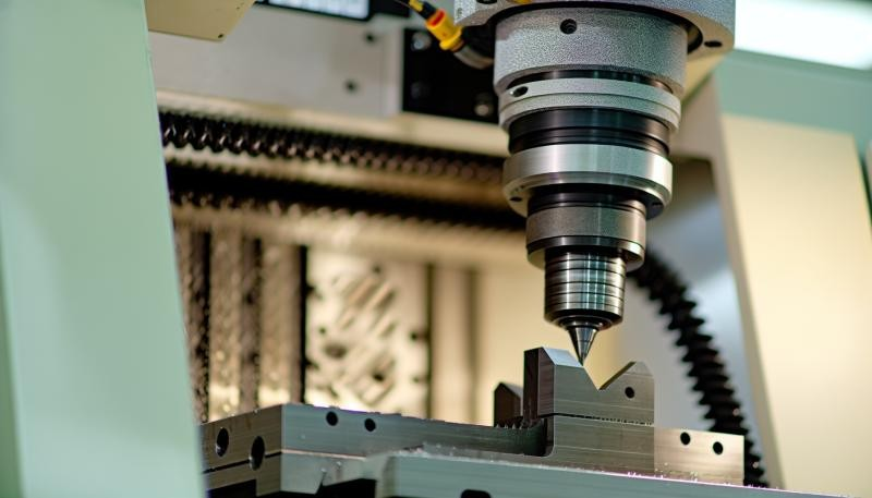
- Milling: In milling, intermittent tool engagement makes it highly susceptible to chatter. Long tool overhangs and high feed rates increase vibration tendency, especially during side milling or pocketing.
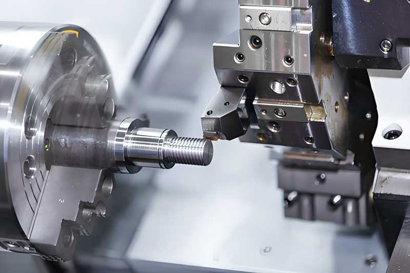
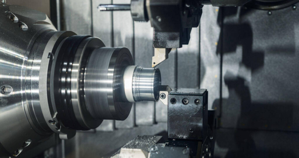
- Turning: In turning, the flexible workpiece or tool setup can trigger self-excited vibrations. Slender shafts or thin-walled components are common sources of chatter, particularly when cutting at high spindle speeds.
- Drilling: Drilling vibrations often arise from uneven cutting edges or misalignment of the drill point. They cause hole tapering, poor roundness, and difficulty maintaining tolerance.
Understanding these distinctions is vital for diagnosing vibration issues. Each machining process requires a different approach to control oscillations, depending on its tool path, contact dynamics, and system stiffness.
Sources of Chatter and Machine Vibrations
Vibration in CNC machining results from the interaction of multiple mechanical, operational, and material factors. No single element causes chatter on its own; instead, it emerges when several weaknesses align in the tool, machine, or workpiece system. Understanding these sources helps identify the root cause instead of simply masking the symptoms.
Tool-Related Factors
Cutting tools are one of the most direct contributors to vibration. Their geometry, length, balance, and condition all influence how forces transfer during machining. Even a small deviation in tool stiffness or sharpness can lead to resonance.
- Tool geometry and overhang length: Long or slender tools have lower natural frequencies and are more prone to deflection. When the tool overhang exceeds three times the diameter, stiffness drops dramatically, increasing vibration risk. End mills, boring bars, and drills with extended reach require special damping or reduced feed rates. Tool geometry also matters. Negative rake angles or large nose radii generate higher cutting forces, while sharp tools with positive rake reduce cutting pressure and vibration.
- Tool wear and imbalance: Worn cutting edges create irregular chip loads and friction, leading to fluctuating cutting forces. Unbalanced tools, especially at high spindle speeds, act like rotating masses that generate cyclic forces on bearings and spindles. Regular regrinding, proper balancing, and tool condition monitoring are essential to prevent forced vibrations.
Machine Factors
The machine tool structure plays a key role in overall stability. Components such as the spindle, bearings, slides, and frame determine the stiffness and damping capacity of the system.
- Spindle rigidity and alignment: A misaligned or loose spindle bearing allows minute radial or axial movement during cutting. This movement leads to repetitive runout errors, which amplify vibrations under load. Precision spindle assembly, proper preload, and dynamic balancing improve vibration control. For high-speed operations, maintaining correct lubrication and bearing clearance is crucial.
- Structural flexibility of the machine frame: The machine base and column act as the backbone of the system. Flexible structures tend to amplify vibrations, especially under heavy cutting conditions. Using polymer concrete bases, cross-ribbed cast iron, or damping materials in the frame can significantly increase rigidity. Even the machine’s foundation, if uneven or poorly anchored, can introduce low-frequency vibrations that affect precision.
Workpiece Factors
Workpiece design and clamping have a direct influence on stability. If the part deflects or vibrates, the tool cannot maintain consistent engagement.
- Material properties and hardness variations: Different materials respond differently to cutting forces. Hard or inhomogeneous materials like titanium or cast iron cause discontinuous cutting, which can excite chatter. Softer materials such as aluminum may produce built-up edges, altering cutting forces periodically. Consistent material quality and proper coolant application can help stabilize cutting conditions.
- Clamping and fixturing methods: Inadequate workholding is a major cause of vibration. Poorly supported parts or flexible fixtures allow the workpiece to move under the cutting load. The result is unstable engagement and variable chip thickness. For long parts or thin walls, using steady rests, tailstocks, or modular clamps improves stiffness. Incorporating vibration-damping materials such as viscoelastic pads can further reduce resonance.
Operational Factors
Even when the machine and tooling are rigid, improper cutting conditions can trigger chatter. The cutting process itself can push the system into instability if speeds and feeds are not matched to the system’s natural frequency.
- Cutting speed, feed, and depth of cut: Increasing cutting speed or feed without considering tool rigidity raises the dynamic load. Every combination of tool and machine has a specific stability lobe diagram, where certain speed ranges are more stable. Reducing the depth of cut or adjusting the spindle speed slightly can move the operation into a stable zone. Modern CAM systems and stability charts help identify these regions.
- Direction of tool engagement and interruptions: Interrupted cuts, such as milling slots or keyways, cause periodic impacts on the cutting edge. Each impact excites the structure, producing transient vibrations. Climb milling tends to generate smoother forces compared to conventional milling because the chip thickness starts high and decreases. Tool path optimization, smoother entry motions, and gradual engagement can significantly reduce dynamic loads.
Effects of Vibration on Machining Performance
Vibrations affect nearly every aspect of CNC machining performance, from dimensional accuracy to tool wear and surface finish. While the causes of vibration may be complex, their impact on part quality and productivity is always visible. Recognizing how vibrations influence machining outcomes helps engineers and operators make informed adjustments to maintain process stability.
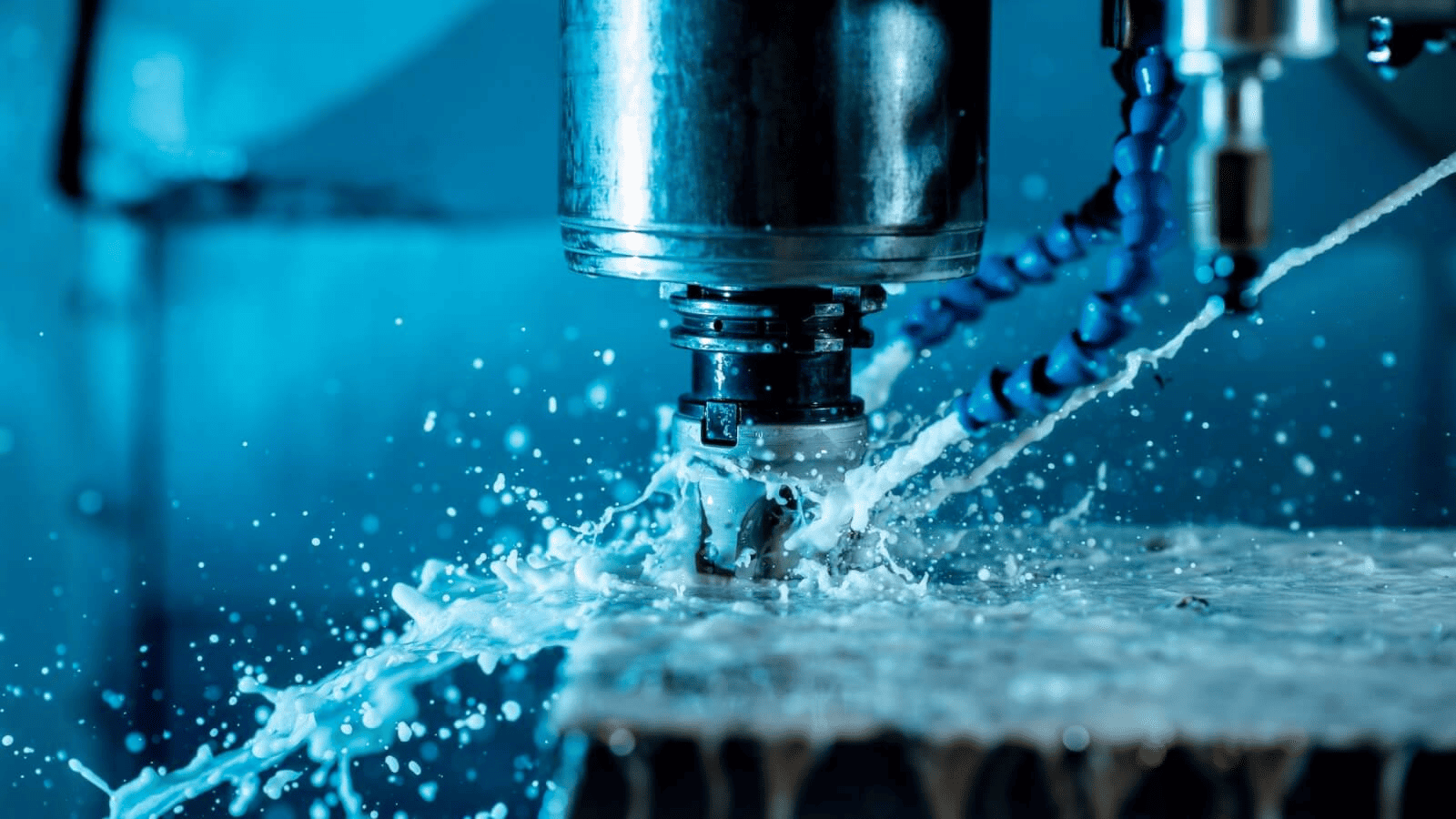
Effects of Vibration on Machining
Impact on Dimensional Accuracy
When a tool vibrates, it no longer follows the programmed tool path precisely. Instead, it oscillates around the intended trajectory, causing dimensional errors and geometric deviations. This effect is most noticeable in tight-tolerance parts where even a few microns of error can make a component unusable.
Key effects include:
- Out-of-round holes in drilling or boring operations
- Tapered or uneven surfaces in turning and milling
- Poor fit between mating parts due to inconsistent dimensions
Over time, continuous vibration also shifts machine calibration. Bearings, linear guides, and ball screws wear faster, leading to long-term loss of precision. Regular accuracy checks and compensation adjustments are necessary when operating under vibration-prone conditions.
Tool Wear and Premature Failure
Vibration accelerates tool wear by increasing friction and generating uneven cutting loads. The fluctuating contact between the tool edge and the workpiece creates alternating stress cycles that fatigue the cutting edge.
Common outcomes include:
- Edge chipping and micro-cracks due to repetitive impact
- Built-up edges caused by unstable cutting temperatures
- The tool tip fractures when chatter amplitude becomes severe
The result is shortened tool life and inconsistent cutting performance. For carbide tools, vibration-induced thermal shock often leads to coating delamination or micro-fracture. Using balanced toolholders, proper coolant flow, and stable cutting speeds can greatly extend tool life.
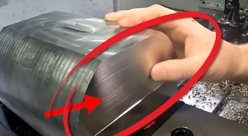
Surface Finish Degradation
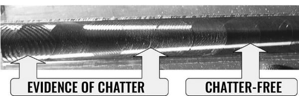
Surface quality is one of the first indicators of vibration problems. When the tool oscillates during cutting, it leaves a periodic pattern or wave on the machined surface. The higher the amplitude of vibration, the more visible the pattern becomes.
Surface finish defects caused by vibration include:
- Waviness and chatter marks along the tool path
- Irregular surface texture or loss of gloss
- Residual stress on the surface that affects fatigue strength
Even when the part appears acceptable visually, microscopic inspection often reveals surface irregularities that influence wear resistance and corrosion behavior. For components such as bearings, molds, or sealing surfaces, maintaining a low surface roughness is critical. Controlling vibration directly improves finish consistency.
Noise Generation and Operational Inefficiency
Noise is often an audible symptom of mechanical instability. Chatter produces a characteristic high-pitched sound caused by the repetitive tool impacts against the workpiece. Apart from being a sign of poor cutting conditions, this noise can also signal unsafe vibration levels that threaten the machine’s mechanical integrity.
Vibrations also reduce operational efficiency by forcing conservative cutting parameters. Operators lower speed, feed, or depth of cut to avoid instability, which reduces material removal rate and increases cycle time. Furthermore, excessive vibration can cause:
- Increased power consumption due to fluctuating spindle loads
- Higher maintenance frequency for spindles and toolholders
- Fatigue for operators due to noise and machine vibration exposure
Reducing vibration helps restore smooth cutting, allowing higher cutting speeds and shorter cycle times without compromising part quality.
Techniques to Reduce Vibration in CNC Machining
Controlling vibration requires a systematic approach that combines mechanical improvements, optimized cutting parameters, and intelligent process monitoring. Each factor in the machining system influences how vibrations develop and propagate. By fine-tuning tool design, workholding, spindle setup, and cutting conditions, machinists can achieve smoother operations and better part accuracy. The following sections explain effective techniques categorized by their application areas.
Tips on How to Reduce Vibration in CNC Machining
Optimizing Cutting Parameters
Cutting parameters directly affect the stability of the machining process. Adjusting them is often the fastest and most cost-effective method to control vibration.
Before making changes, it is important to understand how spindle speed, feed rate, and depth of cut interact with the system’s natural frequency. If a chosen speed coincides with a resonant frequency, even minor forces can trigger chatter. Adjusting these settings shifts the process away from resonance and into a stable cutting zone.
Key parameter adjustments include:
- Spindle speed: Slightly increasing or decreasing spindle speed can move the cutting frequency away from the natural frequency of the tool-holder assembly. This is known as finding a stable speed window.
- Feed rate: A moderate feed rate provides smoother cutting forces. Too low a feed rate may cause rubbing instead of cutting, while too high a rate increases load fluctuations.
- Depth of cut: Reducing axial or radial depth lowers chip load and vibration energy. For finishing passes, use smaller depths to maintain dimensional control.
Proper parameter optimization improves chip formation, reduces tool stress, and minimizes vibration without costly modifications to the setup.
Tooling and Holder Strategies
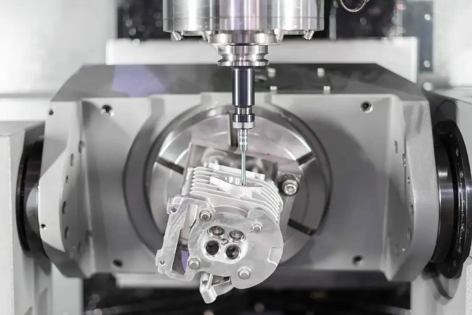
Machining Strategies in CNC Milling
Tool rigidity and balance are essential for vibration-free machining. Every additional millimeter of tool overhang reduces stiffness exponentially. Therefore, selecting the right tool and holder combination is a primary defense against vibration.
- Balanced and rigid tools: Tools with minimal overhang provide greater stiffness. Whenever possible, use the shortest practical tool length for the operation. High-precision tools designed with variable helix or unequal flute spacing help distribute cutting forces more evenly, preventing resonance buildup.
- Damping tool holders: Modern tool holders are engineered with internal damping elements such as viscoelastic materials, hydraulic chambers, or tuned masses. These holders absorb vibrations before they reach the spindle, improving surface finish and tool life. Hydraulic expansion and shrink-fit holders also improve balance and reduce runout compared to conventional collet systems.
Tool selection considerations:
- Use tools with positive rake and sharp cutting edges for smoother entry.
- Opt for coated tools (TiAlN, DLC) to lower friction and stabilize cutting temperature.
- Inspect and balance tools before installation to eliminate forced vibration sources.
Machine Design and Maintenance
Machine stiffness and condition strongly influence vibration levels. Even the best tooling cannot compensate for a flexible or misaligned machine. Proper machine design and preventive maintenance ensure long-term stability.
- Spindle and bearing maintenance: Regular spindle inspection prevents looseness and imbalance. Bearing wear, misalignment, or poor lubrication can introduce radial play that leads to vibration. Scheduled bearing replacement and balance testing help maintain dynamic stability.
- Structural rigidity improvements: Adding cross ribs, damping layers, or polymer concrete in the base enhances machine rigidity. For large machines, installing vibration isolators or anchor bolts reduces the transmission of floor vibrations. Proper foundation leveling ensures even load distribution.
- Routine calibration: Alignment checks for axes, backlash measurement, and laser calibration help maintain precision. Even minor geometric errors can magnify vibration effects during high-speed cutting.
Workpiece Support and Fixturing
The way a workpiece is supported determines how forces are transmitted during cutting. A flexible or loosely clamped part behaves like a spring, amplifying vibration.
- Minimize overhang: Keep the unsupported length of the workpiece as short as possible. For shafts or long components, use tailstocks, steady rests, or additional supports to increase stiffness.
- Secure clamping: Use high-pressure vises, modular clamps, or vacuum fixtures for flat parts. Ensure that clamping pressure is evenly distributed to prevent localized distortion. If clamping forces are uneven, one section may vibrate while another remains rigid.
- Vibration-damping fixtures: Fixtures can be lined with damping materials or designed with tuned mass absorbers to reduce resonance. For thin-walled components, soft jaws or adaptive supports that conform to the part surface help distribute loads more uniformly.
Vibration Damping Techniques
Damping reduces vibration by converting kinetic energy into heat or dissipating it through friction. Both passive and active damping methods are used in modern machining environments.
Passive damping: These methods rely on built-in materials or components that absorb energy without external control. Examples include:
- Damped boring bars with internal mass absorbers
- Vibration-damping coatings or layers on machine structures
- Viscoelastic pads between fixtures and bases
Passive systems are simple, reliable, and maintenance-free, making them suitable for standard production environments.
Active damping: Active systems use sensors and actuators controlled by feedback loops. When vibration is detected, the system generates an opposite-phase signal to counteract it. This technology is used in high-performance machines and robotic systems where precision is critical. Active damping can adjust dynamically to varying cutting conditions, providing superior stability but at a higher cost.
Advanced Solutions
For high-precision industries, advanced technologies help predict and control vibration before it becomes a problem. These solutions integrate simulation tools, sensors, and real-time monitoring to enhance process reliability.
- Dynamic simulation and chatter prediction: Finite element analysis (FEA) and frequency response testing can predict natural frequencies of the tool and machine assembly. Software tools simulate cutting dynamics to identify unstable regions, allowing engineers to choose optimal speeds before machining begins.
- High-speed machining strategies: At very high speeds, cutting forces are distributed over shorter engagement times, which can help avoid resonance. High-speed machining centers designed with lightweight components and high damping ratios operate more smoothly when properly tuned.
- Digital monitoring systems: Modern CNC controls can integrate vibration sensors that record acceleration and frequency data. These signals are analyzed to detect early signs of chatter. Predictive maintenance platforms use this data to schedule interventions before severe damage occurs.
Best Practices for Consistent Precision
Achieving stable and precise machining is not limited to one-time adjustments. It requires continuous attention to setup, maintenance, and process monitoring. Consistency is built by following structured practices that combine technical awareness, preventive maintenance, and operator skill. These practices ensure that vibration remains controlled even as machines, tools, and materials change over time.

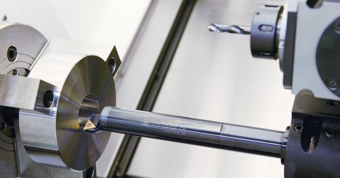
Reducing Chatter and Vibration in CNC Turning
Integrating Tooling, Fixturing, and Cutting Parameters
Stable machining results from balancing all three major components of the cutting system: tooling, fixturing, and cutting conditions. Each element affects the others, and improvements must be coordinated to maintain equilibrium.
- Tooling selection: Choose tools with suitable geometry, high rigidity, and coatings that match the workpiece material. Always inspect for wear before setup to prevent the early onset of vibration.
- Fixturing and support: Ensure all fixtures are tightened uniformly, and parts are clamped with proper alignment. Verify that no section of the workpiece is left unsupported during machining.
- Parameter optimization: Adjust cutting speed, feed, and depth of cut according to stability charts or past experience. Keep records of stable combinations for future reference. Continuous optimization improves efficiency without compromising quality.
Monitoring and Measuring Vibrations
Vibration monitoring provides real-time insights into process stability. Sensors, accelerometers, or even simple spindle-load graphs can help detect changes before defects appear.
- Sensor-based monitoring: Modern CNC machines can integrate vibration sensors that record amplitude and frequency data. The system alerts the operator when vibration exceeds safe limits, allowing timely intervention.
- Data interpretation: Learning to read vibration spectra or load curves enables quick diagnosis of imbalance or chatter. Operators can then adjust speeds or change tools immediately instead of continuing unstable cuts.
- Practical methods for small shops: Even without advanced sensors, machinists can use auditory cues, surface inspection, and spindle-load readings to recognize early signs of instability.
Tool Condition and Maintenance Schedule
A consistent maintenance routine is one of the most effective defenses against vibration. Properly maintained machines and tools retain their designed rigidity and alignment, reducing variability across production runs.
- Tool management: Maintain records of tool life, regrinding cycles, and cutting hours. Replace or resharpen tools before reaching critical wear levels. Consistent tool condition ensures repeatable performance.
- Machine maintenance: Inspect spindles, linear guides, and ball screws regularly. Tighten loose bolts, check belt tension, and verify lubrication. Even minor wear can magnify vibration under load.
- Calibration routines: Schedule geometric and dynamic calibration checks to confirm accuracy. Laser interferometry or ball-bar tests help identify early deviations in axis motion.
Operator Training and Awareness
Operator skill plays a major role in maintaining machining stability. Understanding how vibration behaves allows quick corrective action when conditions change.
- Skill development: Train operators to recognize audible and visual signs of chatter. Encourage systematic problem-solving rather than random parameter adjustments.
- Documentation of experience: Keep a shared database of stable cutting parameters, successful setups, and vibration issues resolved. This collective knowledge reduces trial and error for future jobs.
- Preventive mindset: Encourage routine inspections of fixtures, holders, and workpieces before each job. Small preventive steps save significant time and material later.
Continuous Improvement Through Feedback
Consistent precision depends on iterative improvement. Feedback from production runs should be analyzed and used to refine setups and parameters.
- Data-driven adjustments: Record vibration levels, tool wear data, and surface finish results. Compare outcomes across similar materials or setups to identify trends.
- Cross-functional collaboration: Engineers, machinists, and maintenance teams should communicate frequently. Sharing information about machine condition, tool behavior, and part tolerances helps optimize future operations.
- Review sessions: Regularly reviewing production performance builds awareness and accountability. Documenting recurring vibration issues helps prioritize corrective investments.
Conclusion
Vibration control is one of the defining elements of precision machining. It influences accuracy, surface integrity, tool longevity, and overall productivity. Understanding the difference between forced and self-excited vibrations allows machinists to identify problems early and respond effectively. From the cutting edge to the machine base, every component contributes to stability. Reducing overhang, improving rigidity, balancing tools, and maintaining alignment all help transform an unstable process into a predictable and efficient one.
As machining continues to evolve toward higher speeds and tighter tolerances, mastering vibration control will remain essential. The combination of optimized parameters, damped tooling, stable fixturing, and smart monitoring ensures that quality stays consistent across production runs. By treating vibration as a measurable and controllable variable rather than a random disturbance, manufacturers can achieve smoother operations, improved part performance, and extended machine life, reinforcing precision as the core strength of CNC machining.

