Have you ever thought about the reasons behind so many failed designs? Everything is the result of our careless disregard for how individual components might interact with one another. Every machine you see in the world is made up of various components that have been assembled.
There are many different types of engineering fits, and it can take time to know which one is right for your project. This blog post will discuss the different types of fits and how to decide which one is best for your needs. We'll also provide some tips on creating a custom fit for your project.
So, let’s dive in:
What is a Fit?
Engineered items often consist of moving parts that must slide or rub against one another to perform their tasks. Because of this, we utilize a fit to characterize the dimensional connections between the parts. It helps with slipping or pressing properties by indicating if the components are slack or tight.
Below, we define some key terminology that is necessary for understanding the concept of a fit.
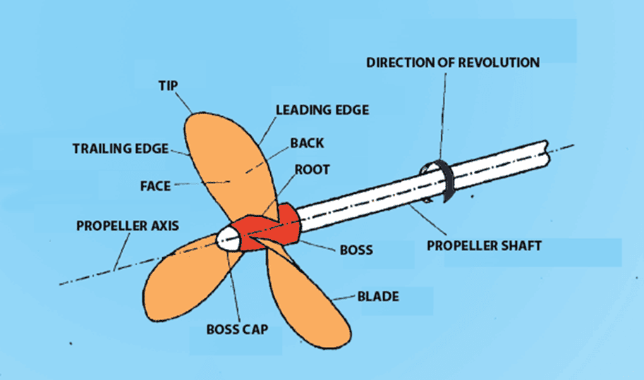
There are two types of main fits shaft and hole. Cylindrical or non-cylindrical internal features of a component are called holes. While external features are called shafts.
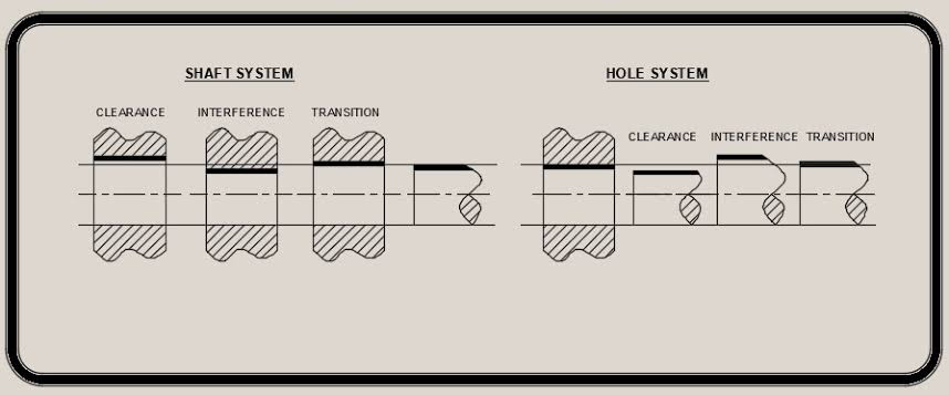
For a hole-based system, the diameter of the hole remains fixed while the length of the shaft is adjusted to get the proper fit. Shaft-based systems, on the other hand, have a fixed shaft size and adjust the hole size accordingly.
NOTE: CNC turning services are a type of precision machining that allows for the production of shafts with precise specifications, making it much simpler to achieve the ideal fit.
Different Types of Fits in Engineering
There are various types of fits that are commonly used in engineering applications. The selection of an appropriate fit for a particular application depends on the required degree of accuracy and the amount of force or load that will be applied.
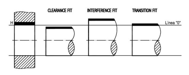
Clearance Fit
Clearance fits permit loose mating in situations when freedom of movement is essential, and some play is needed. In cases where elements need to be able to glide in and out freely and where alignment can be adjusted loosely but does not require perfect precision, clearance fittings are typically required. Clearance fit describes a situation where one feature can glide easily through another feature, such as a bolt or shaft sliding through a hole.
There are five types of clearance fits:
- Slide Fit: It has practically no clearance between moving parts, but the precision and accuracy they provide are exceptional. Examples include automobile assemblies, clutch discs, sliding gears, etc.
- Running Fit: It is required to use the running fit when precision is not crucial, such as when rotating components at a modest speed. The clearances in a running fit are quite big, and the temperatures, speeds, and pressures in the journals fluctuate widely. Example: Couplings, gears, etc.
- Loose Running Fits: For parts that rotate quickly and where accuracy is not crucial, loose running fittings are used. They have a larger clearance. Examples include latches, pivots, heat, corroded or contaminated parts, etc.
- Easy Slide: Easy slide used for tiny clearance between shaft and hole. The easy slide has proven useful for both irregular and slow regular motion. For instance, a piston.
- Location Clearance Fit: It offers extremely small clearance for precise requirements, and with the aid of lubrication, pieces may be put together without effort and can turn and glide free perfectly. For instance, roller guides, shaft guides, etc.
Transition Fit
The shaft tolerance zone in a transition fit is between the lower and middle tolerance zones of the hole, which indicates that the hole is smaller than the shaft.
To get the shaft into the hole, we'll need to apply a little bit of pressure. It's also known as a push fit. The transition fit between two mating pieces is extremely precise and aligns the parts perfectly. Example: Shaft key.
There are 2 types of transition fit:
- Similar Fit: It offers very little clearance or interference, and assembly is possible with the help of a rubber mallet. Examples include bearings, hubs, pulleys, and gears.
- Fixed Fit: It has a tiny clearance or a negligible amount of interference, and it can be put together or taken apart with just a little bit of pressure. Examples include driven bushes, shaft-mounted armatures, plugs, etc.
Interference Fit
A clearance fit is substantially looser than an interference fit. The interference fit, also known as a press fit or friction fit, is a method of joining two parts that necessitate the application of force. Interference fits are commonly utilized when pressing a bushing, dowel pin, bearings, or another component into its complementary part.
Once coupled, this produces a relatively strong union that would call either strong force or possible machine operations to separate.
There are three types of interference fit:
- Tight Fit: It offers less interference than force-fitting alternatives. Examples include a conveyor's stepped pulley, a machine's cylindrical grinding, etc.
- Force Fit: Due to the high interference fit, the shaft and hole must be heated to extremely high temperatures before assembly. The mating components need the help of an outside force to fit together. Examples include shafts and gears.
- Driving Fit: Medium interference is needed, and this can be constructed by greater forces in either cold or hot forging. It's safer to go with a driving fit than a tight one. Examples include gears, bushes, and shafts.
How to Choose the Right Fit for Your Application?
Knowing several factors can help you choose the best fit for your tasks. Some of the most crucial details to keep an eye out for are as follows:
Application
There are many sorts of fits that are perfect for various purposes, depending on what you need. You may choose the best fit for a project by considering factors like precision and tolerance displayed by different kinds of fits and the product's intended function.
Budget
It is important to know your financial limitations before making any choices on the fittings for your products. For instance, employing fittings with tighter tolerances will be more expensive than usual. You should think carefully about the alternatives available to you. A good fit provides the appropriate tolerance required to carry out its operations while keeping product development expenses to a minimum.
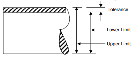
Tolerance
If you want to pick the proper kinds of fittings for a product, you need to understand the concept of tolerance. You need to say exactly what you want. Questions like "do you want the parts to move in a full circle?" and "do you want them to be tight?" require your attention.
Tolerance slack, or the overall maximum or lowest tolerance of a given measurement, is something else you should take into consideration. For instance, when combining various components into a whole, you need to watch out for the sum of their individual tolerances. With a high tolerance as a possible outcome, this is crucial.
Importance of Tolerances in Fits
Tolerances are important in fits because they allow for a certain amount of imprecision in the manufacturing process. By setting tolerances, engineers can account for minor variations in the size and shape of parts. This ensures that components will still fit together properly, even if they are not exactly the same size.
There are two types of tolerances:
- Linear Tolerances
- Angular Tolerances
Linear tolerances are used to specify the maximum permissible deviation from a straight line or desired measurements along a straight line. Angular tolerances are used to specify the maximum permissible deviation from a perfect 90-degree angle.
Tolerances are typically specified in units of millimeters (mm) or micrometers (µm). The smaller the unit of measurement, the more precise the tolerance will be. For example, a linear tolerance of 0.1 mm is more precise than a linear tolerance of 1 mm.
Tolerances are important in engineering because they ensure that parts will fit together properly, even if they are not exactly the same size. By setting tolerances, engineers can account for minor variations in the size and shape of parts. This allows for a certain amount of imprecision in the manufacturing process, which is necessary to produce high-quality components.
Tolerances and fits both play a role in how a product's parts are put together. Therefore, a key component of a good assemblage is having a solid comprehension of both ideas. The "tolerance range" is defined as the number of allowed values between the maximum and minimum sizes. It has a value that is greater than zero and is shown by a number without a symbol.
How to Achieve the Perfect Fit?
In engineering, a poor fit can have serious consequences. A gap or space between two parts that are too small can cause friction, wear and tear, and, ultimately, failure. A gap or space that is too large can cause vibration, noise, and energy loss. So achieving the perfect fit is essential in many engineering applications. Each type of fit has its own advantages and disadvantages, which must be considered when choosing the best fit for a particular application. For instance, a gap or space between two parts that are too small can cause friction, and ultimately a failure. A gap or space that is too large can cause vibration, noise, and energy loss. These are the disadvantages that can occur.
In addition, clearance fits are the loosest type of fit and are typically used when precise alignment is not required. This type of fit lets the parts that fit together move around a little bit, so it's not good for situations where high levels of accuracy are needed. Clearance fits are also more likely to get loose over time, which makes them less good for applications with a lot of movement.
Interference fits are much tighter than clearance fits and are typically used in applications where precise alignment is critical. This type of fit prevents relative movement between mating parts, making it ideal for applications where high levels of accuracy are required. However, interference fits can be difficult to assemble and disassemble, and they are not suitable for dynamic applications.
Transition fits are in between clearance fits and interference fits, and they are the most accurate way to put things together. This type of fit is tight enough to prevent relative movement between mating parts but not so tight that it becomes difficult to assemble or disassemble. Therefore, transition fits are ideal for applications with high accuracy levels, but some flexibility is still desired.
How do you Troubleshoot Fit Problems?
Proper fit is critical to the success of any assembly, from the simplest toys to the most complex aircraft. In engineering, a variety of specialized terms are used to describe different types of fits between parts. It’s important to choose the right fit for your application, as using the wrong fit can lead to a variety of problems, including loose connections, reduced strength, and increased wear.
Within each category of fit, there are a variety of sub-categories that describe how tight or lose the connection will be. For example, a “slip” fit is a type of clearance fit that is slightly tighter than a “press” fit. Similarly, an “interference” fit is a type of interference fit that is slightly looser than a “force” fit.
When choosing a fit for your application, it’s important to consider both the size tolerance of your parts and the required strength of the connection. For example, if you’re assembling two parts with large tolerances (i.e., they could be up to 1/8" larger or smaller than the nominal size), you would want to use a clearance or transition fit so that there’s enough room for them to slide together without binding.
On the other hand, if you need a strong connection between two parts with small tolerances (i.e., they could be up to 1/16" larger or smaller than the nominal size), you would want to use an interference or transition fit so that there’s enough friction to hold them together securely.
For some applications, there may be a need to combine different types of fittings in order to achieve the desired outcome. For example, you might use a slip fit for an initial connection followed by force fit for added strength. Or you might use an interference fit for one part and a clearance fit for another part so that they can be disassembled later if necessary.
Frequently Asked Questions (FAQs)
What is the GD&T limit?
GD&T is a term abbreviated as “Geometric Dimensioning and Tolerancing." Designers use this language of symbols to tell manufacturers important things, like the size and tolerance requirements.
What are the two rules of GD&T?
- Tolerances are required for all dimensions. All dimensions and tolerances must fully describe the nominal geometry and acceptable variation.
- All dimensions and tolerances must fully describe the nominal geometry and acceptable variation. Dimensions are applicable at 20 degrees Celsius. Dimensions and tolerances apply to the object while it is in a free state.
What is H7 fit?
For instance, in the fit H7/h6 (which is frequently used), H7 stands for the hole's tolerance range and h6 for the shaft's tolerance range. Machine operators or engineers can use these codes to rapidly determine the maximum and minimum sizes for either the shaft or the hole.
What are LMC and MMC?
When describing tolerance for mating components, such as a shaft and its housing, the term "maximum material condition" (MMC) is used. On the other hand, the strength of holes close to edges and the thickness of pipes are both shown using the Least Material Condition (LMC) method.
How do you measure the quality of fit?
If you want to know how well your model fits after you've corrected for various coefficients, the adjusted R-squared statistic is your best option. Any value less than or equal to 1 for the corrected R-square value can be considered, with a value nearer to 1 indicating a better match. If the RMSE is close to 0, the fit is good.
Which is the grade of tolerance?
- IT6 – 10 i
- IT7 – 16i
- IT8 – 25i
- IT9 – 40i
- IT10 – 64i
- IT11 – 100i
- IT12 – 160i
- IT13 – 250i
- IT14 – 400i
- IT15 – 640i
- IT16 – 1000i
Conclusion
To conclude, there are three main types of fits in engineering. Each fit has its own advantages and disadvantages. Throughout this article, we provide you with information about fits and the different kinds of fits that are available.
The post also outlined the things you should check out while selecting the best fit for your tasks. More important than knowing the effect of a fit is knowing how to use it. The importance of a good fit and the steps you take to attain it. If any issue arises, you can make the necessary changes.
This concludes the discussion for now. Please share your opinions on this with me. Please tell your loved ones about this post if you found it interesting.
Thanks!