Residual stress is one of the most overlooked factors affecting the performance of CNC-machined components. It sits inside the material with no visible indication, yet it influences how a part behaves during machining, assembly, and real-world use. Many manufacturers focus only on dimensional accuracy, surface finish, and tolerance checks, but the internal stress condition of a part can be just as critical. When ignored, residual stress can lead to distortion, reduced fatigue strength, premature failure, and unpredictable quality issues that are costly to correct once parts reach customers.
How to Prevent Deformation and Residual Stress in CNC Milling Aluminium
Residual stress becomes a concern for precision manufacturing because even a minor imbalance in the internal stress field can cause a finished component to shift from its intended geometry. This often occurs after unclamping, during heat treatment, or even after the part has been in service for some time. Since these stresses cannot be seen and are not always detected during routine inspection, they often appear as sudden and unexplained quality problems.
The purpose of this article is to explain what residual stress is, how it forms during machining, and why it becomes a hidden threat to part quality. You will see how common machining actions such as cutting, heating, clamping, and tool engagement create internal stresses that remain trapped inside the part.
What Is Residual Stress?
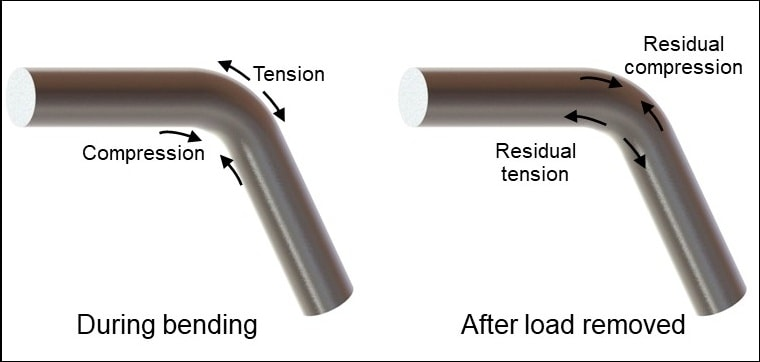
Residual stress refers to the internal stresses that remain locked inside a material after external forces, heat, or mechanical loads are removed. Even when a part appears dimensionally correct and stable, it can hold significant stress within its surface or deeper layers. These stresses are the result of non-uniform plastic deformation or thermal gradients that occur during machining or other manufacturing processes. Although invisible, residual stress influences how a part behaves during later processing or in real use.
Before looking at the types of residual stress, it is important to understand that these stresses exist without any visible signs. A part may pass standard measurement checks and still contain a high amount of internal stress. Once the part is unclamped, heat-treated, or subjected to service loads, the stress begins to redistribute. This movement is what causes unexpected distortion or geometry shifts that catch many machinists and quality teams off guard.
Types of Residual Stress
Residual stress can be broadly categorised into two main types based on how the internal forces act on the material. Each type influences part performance in a different way, and recognising the difference helps in applying the correct stress control method.
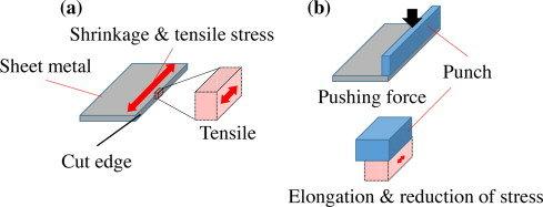
Tensile Residual Stress
Tensile stress pulls the material apart from within. It stretches the metal at a microscopic level, reducing its resistance to cracking and fatigue.
Key effects of tensile residual stress include:
- Higher risk of crack initiation and propagation
- Distortion during unclamping or post-machining processes
- Reduced fatigue life under cyclic loading
Tensile stress is generally considered harmful because it weakens structural integrity and dimensional stability.
Compressive Residual Stress
Compressive stress pushes the material inward. It can improve surface durability and resistance to fatigue because it opposes crack growth. This type of stress is often intentionally induced in processes like shot peening.
Benefits commonly associated with compressive residual stress include:
- Better fatigue strength
- Less risk of surface crack formation
- Improved resistance to wear in some applications
While compressive stress can be beneficial, an imbalance between tensile and compressive zones can still lead to deformation.
How Residual Stresses Remain Trapped
Residual stresses remain inside the part because machining forces or heat alter the material structure beyond its elastic limit. When the external load or heat source is removed, the metal tries to return to its original state, but it cannot fully recover because some deformation becomes permanent. This leaves locked in tension or compression that stays until released by further machining, heating, or stress relieving.
Examples in CNC Operations
Residual stress can form in different machining processes, and the severity varies with cutting conditions.
Some typical scenarios include:
- Milling that causes tensile stress on the cut surface due to tool engagement and heat
- Turning long shafts that develop an imbalance between surface stress and core stress
- Grinding processes that generate high heat in a thin surface layer, leaving tensile stress
Understanding these behaviours is the first step in predicting and controlling stress before it becomes a quality problem.
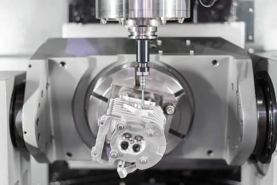
How Machining Induces Stress in Metals
Machining affects the internal structure of a metal part in more ways than simply removing material. Every cut involves mechanical force, heat generation, friction, and interaction between the tool and the workpiece. These factors change the stress distribution inside the material. Some stresses remain elastic and disappear once the load is gone, while others exceed the yield point and become permanent residual stress. The more aggressive or unbalanced the machining process is, the greater the risk of locking in stress that will influence the part during later stages.
Residual stress is rarely caused by one factor alone. It usually results from a combination of mechanical, thermal, and material-related influences. Understanding these causes helps in adjusting machining parameters to produce more stable parts.
Mechanical Causes
Mechanical forces are present in every machining operation. When the cutting edge removes material, it compresses and shears the metal at the tool-workpiece interface. This creates plastic deformation in the surface layer, which can remain as locked-in stress once the cutting forces are removed.
Before discussing specific mechanical sources, it is important to recognise that the severity of mechanical stress is directly linked to tool engagement. High cutting forces, interrupted cuts, or unstable setups increase the risk of surface damage and stress retention.
Cutting Forces and Plastic Deformation
Cutting forces push and pull the surface layer during machining. If the surface yields under this force, it does not fully return to its original state. This leaves a stressed layer that can react later. Higher feed rates and deeper cuts usually increase this effect.
Tool Geometry and Cutting Parameters
The shape, sharpness, and angle of the cutting tool influence how much stress is induced.
Typical contributors include:
- A large nose radius or a negative rake angle raises cutting pressure
- Incorrect feed and speed settings are causing surface tearing or strain
- Dull or worn tools scrape instead of cutting cleanly
Selecting suitable parameters reduces friction, strain, and subsurface deformation.
Tool Wear and Vibration
As tools wear, they generate more friction and require higher cutting force. This raises the chance of inducing tensile stress. Vibration or chatter worsens the problem because the surface repeatedly compresses and relaxes in irregular cycles. This leads to uneven stress patterns that make a part more likely to warp after unclamping or during finishing.
Thermal Causes
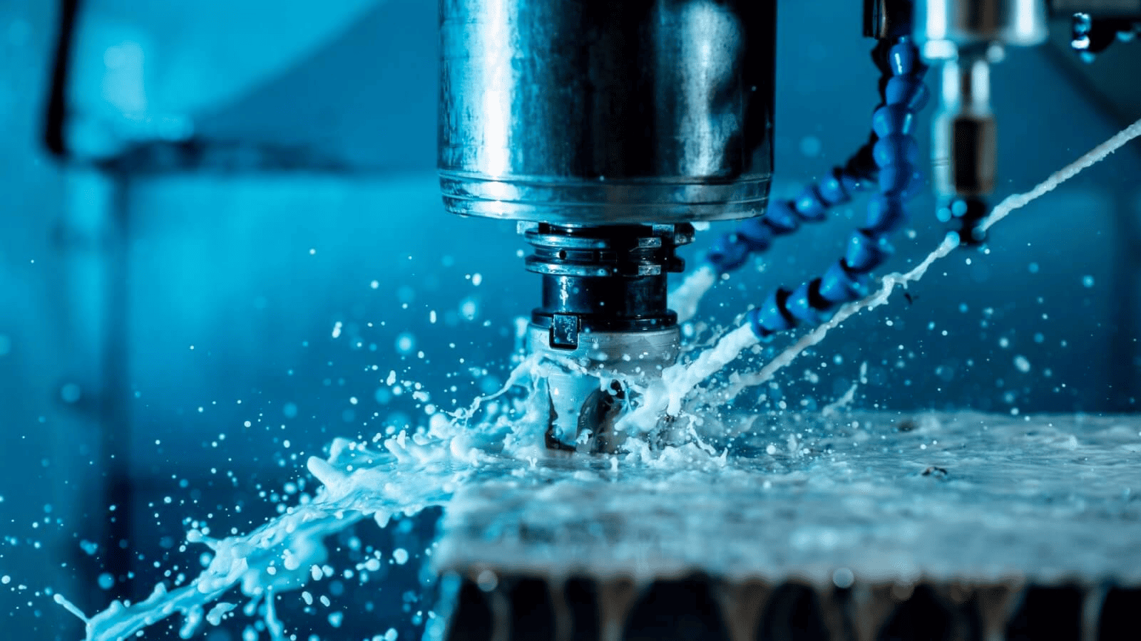
Heat plays a major role in stress formation during machining. The cutting zone can become extremely hot due to friction between the tool and workpiece. If the heat is not controlled, rapid temperature changes can create thermal gradients that transform into residual stress. The outer layer expands when hot and contracts as it cools. If this contraction is uneven, stress remains inside the part.
Before exploring specific thermal sources, it is useful to understand that the temperature imbalance between the surface and the core is the main trigger. The greater the difference, the higher the chance of locked-in stress.
Friction and Heat Buildup
Friction at the cutting interface produces significant heat, especially in dry machining or when using improper coolant flow. This heat softens the surface layer temporarily. When the temperature drops quickly, the surface contracts and can leave tensile stress.
Rapid Heating and Cooling Cycles
Thermal shock happens when machining heats the surface quickly, and cooling occurs too fast. This uneven expansion and contraction creates stress that remains once the part returns to room temperature.
Thermal Conductivity of the Material
The ability of a material to conduct heat affects how temperature spreads.
For example:
- Titanium and stainless steel hold heat at the point of cut, increasing thermal stress risk
- Aluminum dissipates heat faster, which reduces the temperature gradient but can still lead to stress if high cutting speeds are used.
Material and Process Factors
Not all materials respond to machining in the same way. Some metals are more susceptible to stress due to their hardness, grain structure, or work hardening tendency. The machining strategy and part geometry also influence how stress builds up.
Before listing key factors, it is important to note that stress is higher when machining removes material unevenly or when the part design lacks symmetry or adequate rigidity.
Influence of Material Properties
Alloys with high strength or low thermal conductivity tend to retain more stress. Materials that work harden easily, such as stainless steel or nickel-based alloys, often store stress in the surface layer if machining parameters are not controlled.
Stress Concentration in Critical Features
Sharp corners, thin walls, deep pockets, and asymmetrical shapes create weak zones where stress accumulates. Removing material heavily from one side or machining thin features late in the process increases the chance of warping.
Differences Between Roughing and Finishing
Roughing removes large volumes of material and creates significant stress, while finishing aims to refine the surface. If finishing is done too soon after roughing, trapped stress can distort the part between stages. Allowing time for stress redistribution or using intermediate stress relief is beneficial.
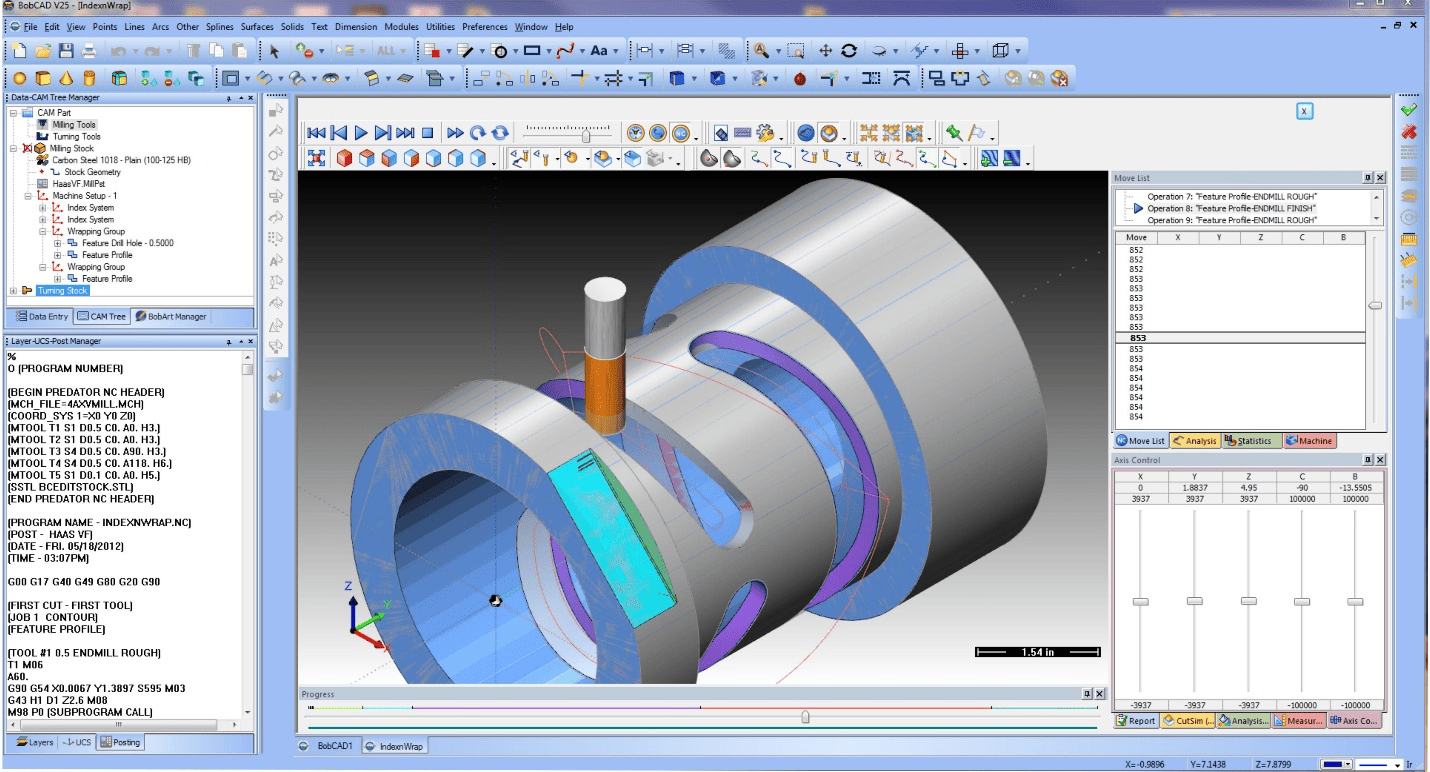
Measurement and Detection
Residual stress measurement allows manufacturers to detect problems early instead of discovering them through distortion or part rejection. Although not always part of routine inspection, stress measurement can save rework, scrap, and customer complaints.
Common Measurement Methods
Several techniques help quantify or reveal stress levels in machined parts. These include:
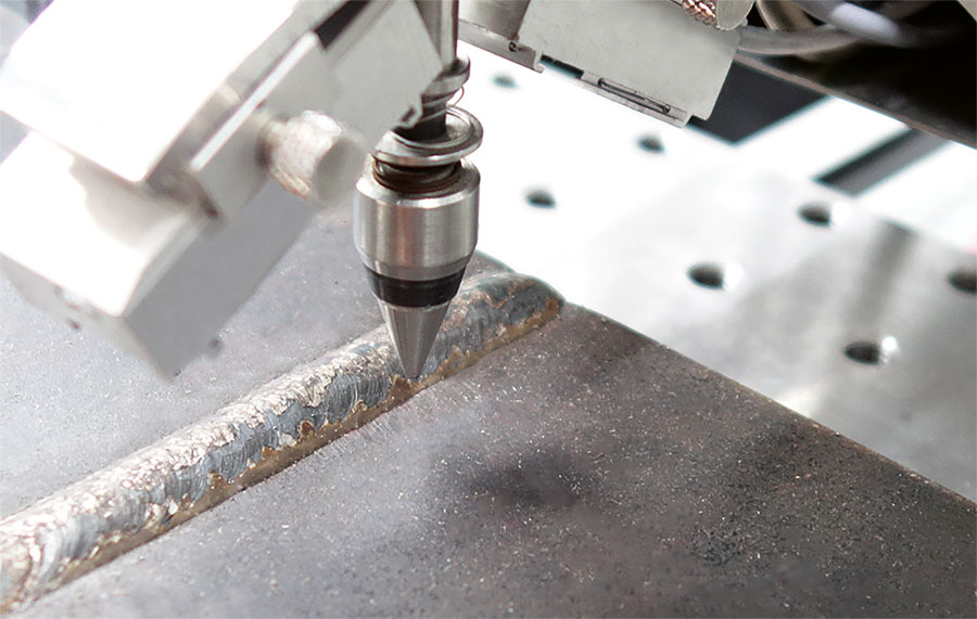
- X-ray diffraction to measure strain at the surface
- Hole drilling to measure stress through depth
- Layer removal to observe the stress relief pattern as material is removed
Each method provides different levels of accuracy and depth of analysis.
Value in Quality Control
Early stress measurement helps identify process issues before mass production. Integrating stress testing into sampling plans or first article inspections ensures that machining parameters, tool paths, and heat inputs produce stable parts. This prevents downstream distortion and supports long-term dimensional reliability.
Distortion After Machining or Heat Treatment
Distortion is one of the most common and frustrating outcomes of residual stress. A part can leave the machine within tolerance, but once unclamped or further processed, its geometry shifts. This dimensional movement often surprises machinists because it is not caused by poor measurement or operator error. It is a natural reaction of the material as locked-in stresses redistribute. Distortion affects flatness, roundness, straightness, and overall dimensional stability, which can result in rework, scrap, or a complete redesign of the machining sequence.
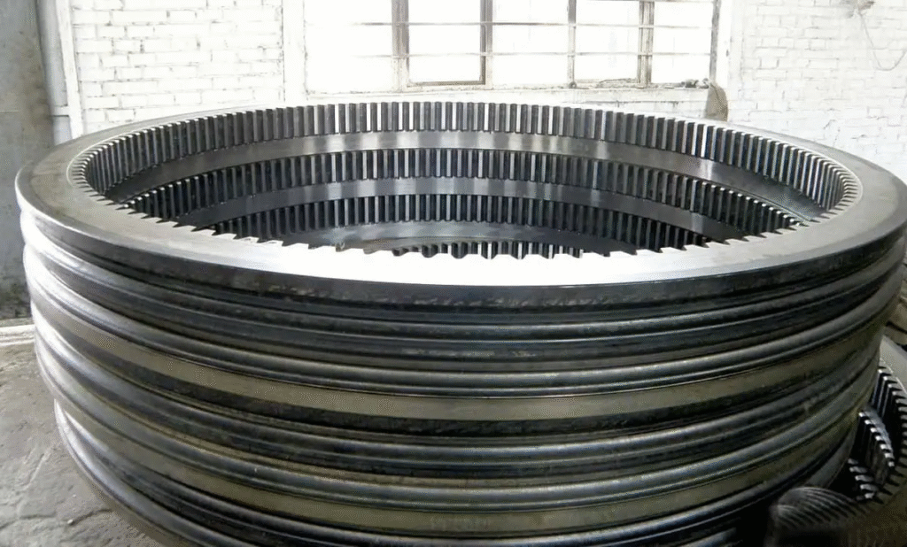
Control of Heat Treatment Distortion in Gear Rings
Understanding why distortion occurs and when it is most likely to appear helps in planning machining, clamping, and stress management strategies more effectively. Most distortion can be avoided or minimised when the machining process is designed with stress in mind rather than reacting to issues after parts begin to warp or bend.
How Stresses Cause Distortion
Residual stresses inside a part are always trying to reach a balanced state. As long as the part is clamped or material remains supporting the internal stress pattern, the stored energy stays contained. Once the external restraint is removed, the material shifts to relieve stress and find equilibrium. This shift alters the shape and causes distortion.
Before looking at specific mechanisms, it is important to recognise that distortion is a stress redistribution phenomenon rather than a machining error. Even high precision equipment cannot prevent distortion if the internal stress is not controlled.
Release of Clamping and Fixturing Forces
During machining, clamping forces hold the part in a constrained position. This stops any stress movement. Once the part is unclamped, the stress redistributes freely, resulting in bending or twisting.
Uneven Stress Through the Cross Section
If one side of the part holds more tensile or compressive stress than the other, the imbalance leads to distortion. Thin or asymmetrical parts are more sensitive because they lack rigidity to resist movement.
When Distortion Happens
Distortion does not always occur immediately after machining. It can appear at different stages of the manufacturing chain. Identifying high-risk stages helps in planning stress relief or adjusting the machining path to stabilise the part before final finishing.
Before listing common scenarios, it is useful to note that distortion often appears after a change in temperature, load, or material removal, since these events trigger stress release.
After Removing Material from One Side
If heavy material removal is done on one face, the stress becomes unbalanced. The machined side becomes thinner and more flexible, allowing the stored stress to bend the part. This is common in plates, brackets, and thin-walled components.
During or After Heat Treatment
Heat treatment relaxes or redistributes internal stress. If the part was already stressed from machining, heat exposure can cause sudden movement as the metal structure changes. Distortion often appears during quenching, ageing, or tempering.
After Long-Term Storage or Temperature Fluctuations
Even after machining and inspection, parts can deform during storage due to temperature changes. Heat causes expansion, and cold causes contraction. If the internal stress pattern is uneven, these changes trigger subtle movements that grow over time.
Real World Examples
Distortion affects many industries, especially where tight tolerances or thin geometries are required. The following examples show how residual stress can create practical problems that disrupt production schedules and increase costs.
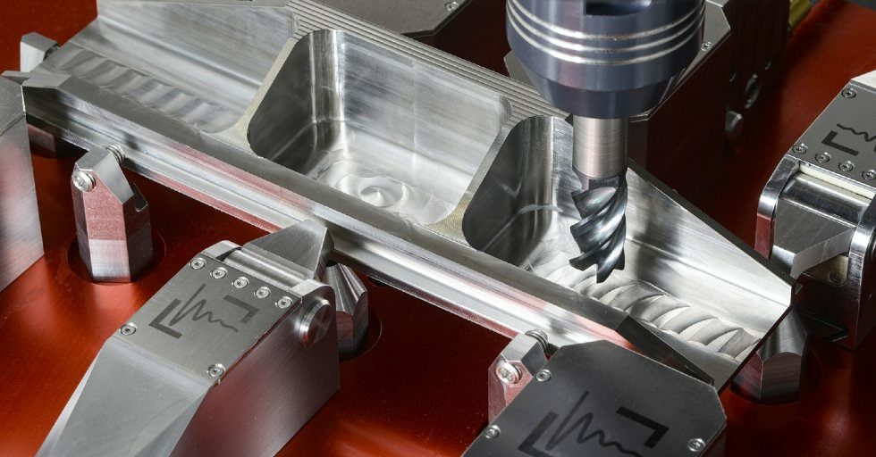
Reducing part distortion during milling
Before reviewing them, it is important to acknowledge that these issues are often misdiagnosed as fixture errors, incorrect tool paths, or measurement mistakes, even though stress control is the root cause.
Thin-Walled Aerospace Components
Aircraft structural parts often involve high-strength alloys and significant material removal. A thin-walled rib or bracket may look perfect during machining, but bends once unclamped because internal stress was trapped during roughing.
Shafts and Plates After Grinding or Hardening
Grinding introduces heat in a shallow surface layer. Shafts can lose roundness or straightness if the grinding passes create uneven tensile stress. Plates may change flatness after hardening because thermal cycles amplify the initial machining stress.
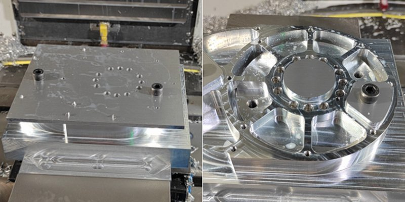
Precision Molds Losing Flatness After Polishing
Polishing applies mechanical pressure and heat over small areas. This can release surface stress unevenly, causing mold inserts or cavity plates to lose flatness. Even a small change affects mold fit, sealing, and part quality.
Preventive Design and Machining Practices
Distortion prevention begins at the planning stage. Once the part is distorted, fixing it usually requires rework or another full machining cycle. Incorporating stress control measures into design, fixturing, and machining helps the part remain stable throughout its lifecycle.
Before introducing practical techniques, it is important to view distortion prevention as a combination of good design, balanced machining, and controlled stress relief, rather than a single corrective step.
Balanced Machining and Material Removal
Removing material evenly from both sides helps maintain stress balance. Techniques such as alternating machining sequences, step-down material removal, or mirror machining paths support stability.
Clamping and Fixturing Considerations
Use fixturing that supports the part without over-constraining it. Uniform clamping pressure and proper support reduce stress concentration. Soft jaws, vacuum fixtures, and modular supports help distribute load more evenly.
Intermediate Stress Relief During Machining
For high-accuracy parts, adding a stress relief step between roughing and finishing allows the material to settle before final machining. This step can be a short thermal cycle or a controlled rest period to stabilise the part.
Material Choice and Cooling Control
Selecting materials with stable microstructures or pre-stress relieved bar stock reduces the risk of distortion. Gradual cooling after machining avoids sudden contraction that triggers stress movement. Whenever possible, avoid quenching or rapid cooling of a freshly machined part.
Stress Relieving Methods
Managing residual stress is not about eliminating stress completely, but controlling it to ensure dimensional stability and long-term performance. Several methods are used to reduce or redistribute stress depending on the material, geometry, and application needs. Choosing the right approach requires understanding how each method works, where it is most effective, and what limitations may apply. Stress relief is most valuable when carried out at the correct stage of manufacturing rather than after distortion has already occurred.
Before exploring the specific techniques, it is important to recognise that stress relief should be seen as a planned step rather than a last resort. Integrating stress management into the process flow supports consistent part quality and reduces rework.
Thermal Stress Relief
Thermal stress relief is the most widely used and reliable method for reducing residual stress. It involves heating the part to a controlled temperature below the material’s transformation point, holding it for a specific duration, and allowing it to cool slowly. This helps atoms in the metal relax and redistribute, reducing internal stress levels throughout the part.
Before examining temperature ranges or procedures, it is helpful to understand why thermal exposure is effective. Heat increases atomic activity, allowing strained regions in the microstructure to settle into a more stable arrangement. Slow cooling ensures that no new stress forms during the return to room temperature.
Heating Below Transformation Temperature
The part is heated to a level where stress relaxation can occur without altering the material’s mechanical properties. The temperature depends on the alloy.
Typical stress relief temperatures:
- Carbon and alloy steels: 500 to 650°C
- Stainless steel: 450 to 600°C
- Aluminum: 150 to 200°C
- Titanium: 425 to 595°C
The part is held at a temperature for a period often ranging from one to four hours, depending on size and material thickness.
Controlled Cooling to Prevent New Stress
Cooling too quickly can create fresh thermal gradients, causing stress to return. A slow, furnace-controlled cooling process protects dimensional stability.
Advantages and Limitations of Thermal Stress Relief
Thermal stress relief provides uniform results and is suitable for most metals. However, it has some constraints.
Advantages include:
- Proven and reliable stress reduction
- Suitable for most common industrial alloys
- Helps stabilise parts before finishing or grinding
Limitations include:
- Longer process time
- Additional cost for furnace treatment
- Risk of oxidation and scaling on exposed surfaces
Vibratory Stress Relief
Vibratory stress relief is a mechanical alternative used when thermal treatment is impractical due to part size, geometry, or cost. This method uses controlled vibration to redistribute stress. It does not remove stress completely, but balances internal forces so the part becomes dimensionally stable.
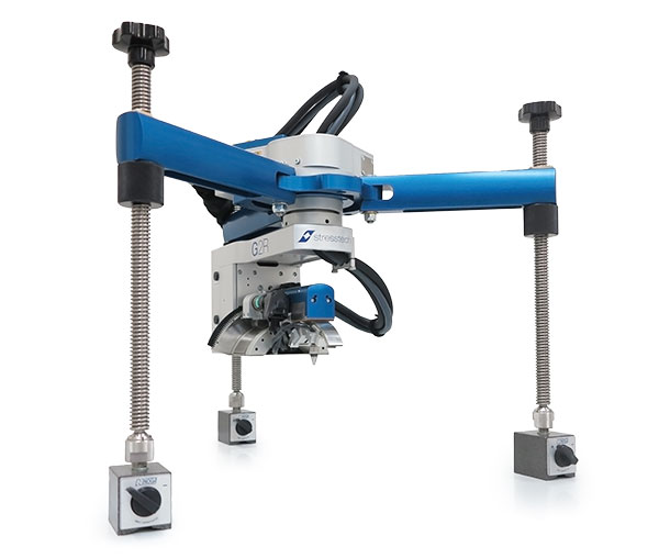
Vibratory Stress Relief Testing
Before looking at its application, it is important to understand that vibratory methods do not alter material properties. Instead, they help the metal shift into equilibrium through microyielding.
How Vibratory Stress Relief Works
The part is mounted on a vibration platform, and mechanical vibration is applied at specific frequencies. These vibrations cause slight movement in the material’s internal structure, allowing stresses to equalise without heat exposure.
Steps in the Process
- The part is clamped to a vibration table in a stable orientation
- Sensors measure vibration response
- Frequency is adjusted to reach a resonant state
- Vibration continues for a fixed duration until stress stabilisation is achieved.
Benefits and Uses
Vibratory stress relief is often chosen for very large or complex parts that would be expensive or difficult to fit in a furnace.
Benefits include:
- Suitable for large weldments and machined structures
- Shorter processing time
- Lower cost compared to thermal treatment
While effective for dimensional stability, it does not change material properties or relieve stress as thoroughly as thermal treatment. Precision critical parts may still require supplementary methods.
Other Techniques
Several additional methods support stress control, especially when combined with machining or finishing processes. These techniques either enhance surface stability or adjust material behaviour to better resist distortion.
Before reviewing them, it is useful to note that these methods are often secondary options, used when thermal or vibratory relief alone is insufficient.
Cryogenic Treatment
Cryogenic treatment exposes the part to extremely low temperatures using liquid nitrogen. This reduces retained austenite in steels and enhances dimensional stability. It is commonly used for tool steels and precision components.
Shot Peening
Shot peening bombards the surface with small spherical media. The impact creates a thin compressive layer on the surface, which offsets tensile stress and improves fatigue strength. It is widely used in the aerospace and automotive industries.
Low Stress Machining Techniques
Adjusting machining parameters to reduce stress formation is often better than removing stress later. This includes using sharp tools, lighter finishing cuts, consistent coolant application, and stable fixtures. The goal is to avoid excessive strain or thermal shock during machining.
Surface Treatments and Post-Machining Processes
Processes such as polishing, honing, or superfinishing can help stabilise surface layers by smoothing peaks and reducing stress concentrations. They are often applied to critical sealing or contact surfaces.
Choosing the Right Method
Selecting a stress relief method depends on several factors. No single technique suits every material or part. A careful assessment ensures the chosen method supports dimensional accuracy and cost efficiency.
Before outlining key selection factors, it is important to consider the stage of manufacturing. Applying stress relief before final machining often gives the best results.
Factors to Consider
- Material type and thermal sensitivity
- Part geometry, especially thin walls or asymmetrical designs
- Required dimensional stability and tolerance levels
- Budget, processing time, and available equipment
For example, high-strength steels benefit from thermal stress relief, while large structural components may be better suited for vibratory treatment.
Combining Methods for Optimal Stability
In some cases, combining methods offers the best outcome. A common approach is to rough machine, apply thermal stress relief, then finish machine, followed by a surface enhancement such as shot peening for fatigue resistance. This layered approach strengthens both internal stability and surface durability.
Conclusion
Residual stress remains hidden inside machined parts, yet it has a powerful influence on dimensional accuracy, performance, and service life. It is not visible during machining, and standard inspection alone cannot detect it. When ignored, these stresses reveal themselves through distortion, premature failure, or inconsistency between batches. By recognising residual stress as a key quality factor, manufacturers can take proactive steps that protect part stability and reliability.
Managing residual stress is not limited to one technique. It begins with balanced machining strategies that avoid unnecessary strain or thermal shock. When needed, stress relief methods such as thermal treatment, vibratory processing, or controlled finishing help stabilise the material. Monitoring stress during first article inspections and integrating predictive tools further strengthens quality control. Each step contributes to a more stable process and reduces costly rework or customer returns.