1.0 Introduction
One of the most common CNC machining processes used to create non-rotating, non-cylindrical items utilized in a variety of industries is milling. High-speed milling cutters are used by the milling machines to form the work product into the required shape. The cutter makes little chips out of the metal on the work piece. Once the cutting is done, these chips are removed from the work piece. These chips come in a variety of forms and sizes according on the materials used in the workpiece, the cutting environment, and any deformation that occurred throughout the operation. The resulting chips are often classified according to their forms as continuous chips, non-continuous chips, continuous chips with build-up edge, and non-homogenous chips.

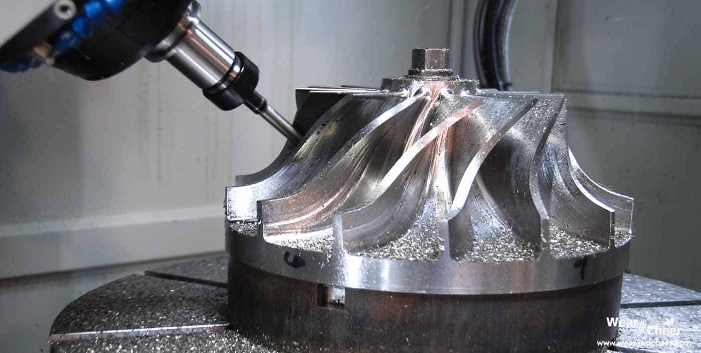
1.1 The processing technology of the milling machine
Milling is the technique of processing a workpiece into the required form and size by contacting it quickly with a milling cutter. During this milling procedure, the milling cutter separates the metal chips from the processing surface by cutting the metal on the work piece's surface into chips as well as by pushing and spreading the blade surface. The tension in the work piece steadily increases as the workload increases, with the stress at the point of contact with the blade edge being the biggest. This is the cutting effect of the blade. The metal substance cracks and separates first where the tension is greatest and most concentrated on the work piece.
As a result, the blade's cutting action always causes the separation of the metal surface layer material from the metal substrate of the work piece to form first. The metal to be cut will be split along the direction of the blade movement to produce a processed surface when sufficient mechanical force is applied while the tool and workpiece continue to move relative to one another. The cutting layer deforms both elastically and plastically as a result of the pressure in front of the tool, eventually forming chips that flow out along the tool's front. In front of the tool, this is the pushing effect.
Under the action of the cutting edge, the cut metal generates four deformation areas: front and rear of the tool, the basic deformation area, the friction deformation area in front of the tool, the deformation region in front of the blade, and the friction behind the tool Deformation zone. In the four deformation zones, there are relationships between and interactions between the internal stress states and deformation circumstances.
2.0 Chip types and their formation conditions
The metal in front of the tool contracts throughout the cutting as it moves further into the workpiece. Compression that is too great results in the metal separating from the workpiece and flowing plastically in the shape of a chip (shear deformation). The main shear causes the metal to flow at the shear plane. The uncut surface in front of the tool is where the shear plane begins to extend at an angle upward. The shear angle value is influenced by the kind of material and the cutting circumstances. When the shear angle is modest, the shear path is lengthy, the chips are thick, and the cutting force is large. The opposite is also true. The secondary shear is caused by friction as the chip moves over the tooltip's face. The chips overheat as a result of the friction raising the operating temperature of the milling process.
The four primary categories of chips created by a milling machine are as follows: Discontinuous Chip; Continuous Chip; Continuous Chip with Built-Up Edge; Non-homogeneous Chips.
2.1 Discontinuous Chip
Discontinuous chips have an irregular shape and often deform as a result of repetitive fracture. Cast iron, brass, and bronze are just a few examples of the hard, delicate metals whose work pieces are known to create discontinuous chips. In conditions when there is substantial friction between a work piece and tool, ductile workpieces can also result in discontinuous chips. A tool with a short rake angle, a rapid cutting speed, a deep cut in the material, and other factors might result in the formation of discontinuous chips.
Brittle materials can have their surface finishing improved and their power consumption decreased through the formation of discontinuous chips. In ductile materials, however, the development of discontinuous chips results in a subpar surface polish and might lengthen the machining process.

2.2 Continuous Chips

Continuous chips typically form when metals that are malleable, like steel, copper, or aluminum, are machined at high cutting speeds. The temperature difference between the tooltip and the ductile workpiece increases during the cutting process. A lengthy and continuous chip stream is created when successive layers of the removed metal are joined together by welding. The following machining circumstances typically result in continuous chips:
- minimal cut depth
- extensive rake angle
- high rate of cutting
- using lubricants or coolants to reduce tool-chip friction
- sharp cutting edge
Continuous chips offer a smooth surface quality, increased tool longevity, and less power usage. However, it might be difficult to dispose of certain kinds of chips. Chip breakers are required to enhance disposal conditions.
2.3 Continuous Chip with Built-Up Edge
High friction between the tool and the chip when cutting ductile metals leads to the creation of continuous chips with the BUE.Some chip fragments have a tendency to adhere to the tooltip under these circumstances. The new cutting edge continues to develop up as bonded material until it separates from the tooltip. A poor surface finish results from the built-up material's bonding to the chip and the workpiece surface during the breakoff process. The process of forming BUE is often referred to as "chip welding. The following circumstances typically result in continual chipping with BUE:
- Low angle of rake;
- low rate of cutting;
- high forces of friction;
- large feed.
Continuous BUE chips have a negative impact on tool life, increase power consumption, and result in subpar surface finishes, hence their avoidance is essential.
The prevention of chip welding can be enhanced by taking steps to reduce friction by using lubricants, avoid metal-on-metal contact by using tool coatings, and lower temperature by using coolants.
2.4 Serrated Chips
Serrated chips, also known as non-homogeneous chips, are semi-continuous. Because of the low and high shear strain zones, they have a saw-tooth look. The materials used to make these chips typically have limited thermal conductivity or mechanical strength that is affected by thermal softening. Materials used in work pieces that can produce non-homogeneous chips during machining include nickel, austenitic stainless steel, and titanium alloys. One of the reasons of non-homogenous chips is a significant amount of strain that forms at the tool's chip surface while cutting hard materials at medium cutting speeds.
3.0 Comparison between Continuous, Discontinues and Continuous Chips with Built up Edge
The table below compares and contrasts Continuous, Discontinues, and Continuous Chips with Built up Edge.
| S.no | Factors | ContinuousChips | DiscontinuousChips | Continuous chips with Built Up Edge (BUE) |
| 1. | Material types | Ductile | Brittle, ductile but hard | Ductile |
| 2. | Rake angle | Large | Small | Small |
| 3. | Cutting speed | High | Medium or high | Low or medium |
| 4. | Friction between chip tool interface | Minimum | Maximum | Maximum |
| 5. | Depth of cut | Small | High | Medium |
3.1 Chip Control
The creation of long and stringy chips occurs when malleable metals, such as steel, are machined at fast cutting speeds and significant rake angles. The safety of machine workers may be at risk, and the product may be harmed by becoming entangled with the tool. Additionally, the removal of these hot, continuous, and sharp-edged chips can be challenging. Chips must be broken into manageable sizes. Chips can separate by either self-breaking or forced breaking. The chips often curl while cutting ductile materials because to the differential in temperature and flow rate. The three various methods the curled chips can self-break are as follows:
- by strain caused by cooling that results in spontaneous fracture;
- via impacting the workpiece;
- by making contact with the tool.
Making use of a chip breaker is by far the most typical forced breaking technique.
3.2 Chip Breakers
The most fundamental purpose of chip breakers is to make chips coil more tightly than they would otherwise. The chip breaks off during forced curling when it strikes the tool or the workpiece. Chip breakers boost chip control and lower cutting forces, which increases machining efficiency.

Most contemporary chip breakers are found on the cutting tool as grooves or obstacles. The key to creating the tension that will allow the chip to readily break off is to discover the appropriate shape for a certain machining scenario when designing chip breakers. The leading cutting edge of groove type chip breakers has a little groove behind it.
The radius of chip curvature is a function of curve shape. The geometric design of obstruction type chip breakers is unusual and resembles a step. The obstacle may be separate from the cutting instrument or affixed to it. For the "attached" kind, they may be altered for varied machining circumstances.
4.0 Conclusion
Physics and material science are delicately woven together throughout the milling operation. The interplay of stresses between the workpiece and the cutting tool during the milling process results in the removal of material. Color and chip size are determined by the nature of these contact forces. The chips include useful information for cutting engineers' research and diagnostics. However, if chips aren't handled correctly, they can lead to a reduction in machine productivity. During the machining, segmented, continuous, and continuous with BUE chips of three different sorts may appear.
The parameters of the milling operation and the material choice both affect chip formation.
When enhancing overall milling effectiveness and making plans for the machines' autonomous operation, chip disposal is a crucial element to take into account. As a general rule, chip breakers should be used in milling settings even if segmented chips and continuous chips can self-break under certain machining circumstances.
Chip entanglement with the tool, vibration, and tool damage are all avoided when the chips are broken by a chip breaker into manageable lengths. Additionally, chip breakers lessen cutting resistance, which keeps the cutting edge from chipping and breaking. It’s important to pick the appropriate chip breaker for the job while employing one. We must select the appropriate chip breakers for each turning operation, such as finishing, medium, and roughing. Use a chip breaker that is appropriate for the intended depth of cut, feed rate, spindle speed, and surface polish.