Struggling with precision issues in sailboat winch manufacturing? We've seen countless winches fail due to tolerance problems, leading to catastrophic failures during crucial sailing moments. Precision isn't just desirable—it's essential for safety and performance.
Achieving precision tolerances in sailboat winch manufacturing requires specialized CNC machining techniques with tolerances typically within ±0.001-0.003 inches (0.025-0.075mm). Success depends on proper material selection, vibration control, multi-axis machining strategies, and specialized quality control processes tailored to marine applications.
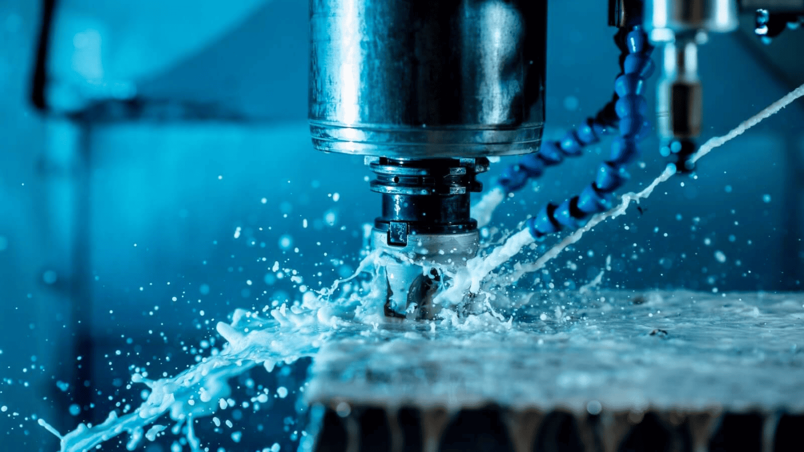
High-precision CNC machining process for custom sailboat winch components
As a manufacturer with extensive experience in marine component machining, I've learned that precision winch manufacturing requires more than just standard machining knowledge. Let me share our proven approach to achieving the tight tolerances that ensure both performance and durability in the challenging marine environment.
What Are the Critical Tolerance Requirements for Sailboat Winches?
Sailboat winches fail at the worst possible moments when tolerances aren't precisely maintained. We've seen racing teams lose competitions and cruisers face dangerous situations due to winch failures that could have been prevented.
Critical tolerance requirements for sailboat winches include bearing seat tolerances of ±0.0005" (0.0127mm), gear tooth precision within ±0.001" (0.025mm), and axial clearances of 0.002-0.005" (0.05-0.13mm). These strict requirements ensure smooth operation, load distribution, and longevity in corrosive marine environments.
Diagram showing critical tolerance zones on sailboat winch parts
When machining custom sailboat winches, understanding the functional relationship between components is essential for proper tolerance specification. From our experience working with top sailboat manufacturers, I've learned that winch performance relies on several critical tolerance aspects.
The most demanding tolerance requirements are typically found in the bearing seats and gear interfaces. Bearing seats must maintain roundness within 0.0005" to ensure proper load distribution and prevent premature wear. Gear teeth profiles require precise machining to maintain proper tooth engagement angles—typically within 0.001"—to ensure smooth operation under varying loads.
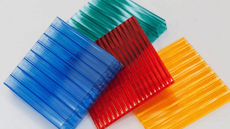
Material selection significantly impacts tolerance capability. We primarily use 316L stainless steel or specialized marine-grade aluminum alloys (such as 6082-T6) for winch components. While aluminum allows for faster machining speeds, stainless steel components generally maintain tighter tolerances over time due to superior dimensional stability.
We've implemented a tolerance stacking analysis process for every winch design to identify critical interfaces where cumulative tolerances might cause problems. This mathematical modeling approach helps us adjust individual component tolerances to achieve optimal assembly fit. For example, in self-tailing winch mechanisms, we maintain tighter radial tolerances (±0.0003") at the interface between the drum and self-tailer to prevent line jamming under load.
| Component | Critical Tolerance | Typical Material | Key Considerations |
|---|---|---|---|
| Bearing Seats | ±0.0005" (0.0127mm) | 316L Stainless | Roundness, surface finish |
| Gear Interfaces | ±0.001" (0.025mm) | 17-4PH Stainless | Tooth profile accuracy |
| Pawl Mechanisms | ±0.002" (0.05mm) | Phosphor Bronze | Engagement consistency |
| Drum Surface | ±0.003" (0.075mm) | Anodized Aluminum | Grip texture uniformity |
| Axial Clearances | 0.002-0.005" (0.05-0.13mm) | Multiple | Load distribution |
What Machining Strategies Minimize Vibration and Deflection Issues?
We once lost an entire batch of winch drums due to tool deflection issues. The subtle dimensional variations weren't visible to the eye but caused binding under load. Since implementing advanced vibration control strategies, our rejection rate has dropped to near zero.
Effective vibration minimization in winch machining requires rigid workholding with custom fixtures, optimized cutting parameters (feed rates of 0.001-0.003 ipr, cutting speeds of 300-500 SFM for stainless steel), high-frequency tool monitoring, and harmonics analysis. Multi-axis machining with shorter tool overhangs further reduces deflection problems.
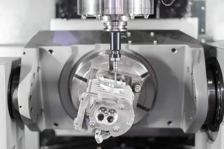
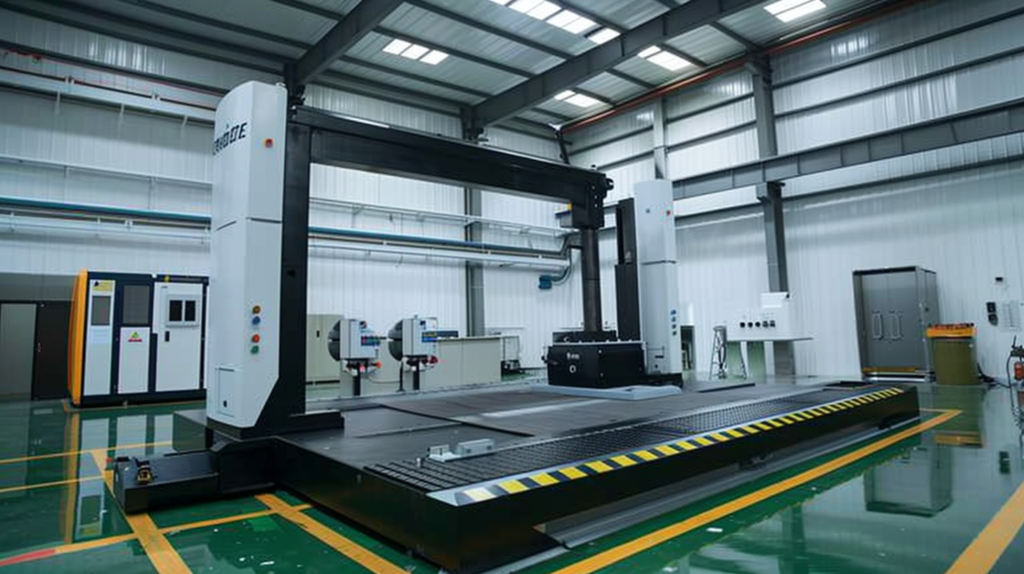
Specialized workholding fixture minimizing vibration during winch component machining
Vibration and tool deflection represent the greatest enemies of precision tolerance achievement in winch manufacturing. Our approach combines both traditional machining wisdom and modern technology to overcome these challenges.
Proper workholding forms the foundation of our vibration control strategy. We've developed customized vacuum fixtures that distribute clamping forces evenly across the workpiece, preventing distortion while maintaining accessibility for 5-axis machining operations. For thin-walled components like winch drums, we utilize internal support structures that are removed in later operations.
Tool selection and tool path strategies dramatically impact vibration profiles. We've found that variable helix end mills significantly reduce harmonic vibration when machining the internal gear profiles of winch components. For deep features, we implement peel milling strategies with progressive depth increases rather than traditional slotting, which reduces cutting forces and associated deflection.
Cutting parameter optimization through real-time monitoring has transformed our ability to maintain tight tolerances. Our advanced machining centers incorporate accelerometers that detect vibration patterns before they affect dimensional accuracy. The control systems automatically adjust feed rates and spindle speeds to maintain optimal cutting conditions. For stainless steel components, we typically operate with cutting speeds between 300-500 SFM and feed rates between 0.001-0.003 inches per revolution.
Thermal stability represents another critical factor in maintaining tolerances. Our temperature-controlled manufacturing environment maintains conditions within ±2°F to prevent thermal expansion issues. For the most critical components, we implement in-process measurement using touch probes to compensate for any thermal growth during machining operations.
| Vibration Control Method | Application | Benefit to Tolerance Control |
|---|---|---|
| Custom Vacuum Fixtures | Thin-walled components | Prevents distortion while maintaining access |
| Variable Helix End Mills | Internal gear profiles | Reduces harmonic vibration |
| Peel Milling Strategies | Deep features | Minimizes cutting forces and deflection |
| Real-time Vibration Monitoring | All operations | Allows adaptive parameter adjustment |
| Temperature-Controlled Environment | Entire process | Prevents thermal expansion variation |
| In-Process Measurement | Critical dimensions | Compensates for thermal changes |
What Quality Control Methods Ensure Consistent Tolerance Achievement?
After implementing our comprehensive quality control system, we caught a subtle bearing seat tolerance drift that would have resulted in premature failures. Our customers never experienced the problem because our detection system identified and corrected the issue before parts were shipped.
Effective quality control for sailboat winch manufacturing combines real-time process monitoring, coordinate measuring machine (CMM) verification of critical dimensions (accurate to 0.0001"), optical comparators for geometric verification, statistical process control (SPC) with Cpk values >1.33, and environmental simulation testing to validate performance under marine conditions.
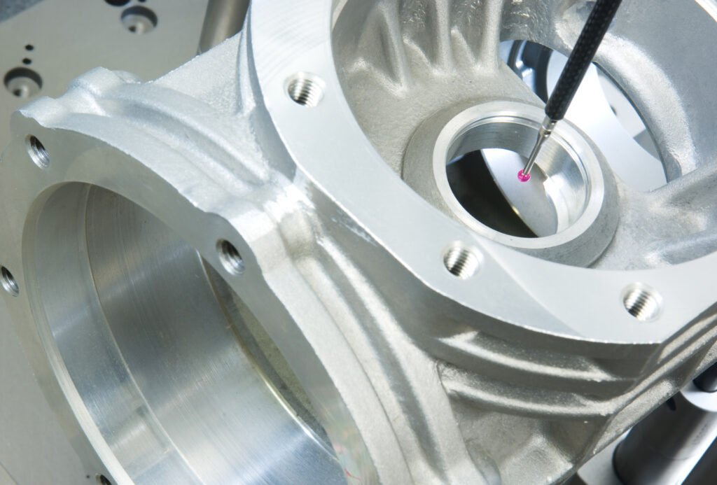
Precision measurement of the winch component using a coordinate measuring machine
Quality control in precision winch manufacturing must be integrated throughout the production process rather than applied only at the end. Our multi-layered approach begins with material certification and extends through post-processing verification.
In-process measurement forms the cornerstone of our quality system. Our CNC machines are equipped with touch-trigger probes that verify critical dimensions during machining operations. For bearing seats and gear interfaces, we perform 100% in-process measurement, with automatic tool compensation algorithms that adjust for any detected tool wear before tolerance limits are exceeded.
Post-machining inspection utilizes climate-controlled CMM verification with measurement capabilities accurate to 0.0001". We've developed custom measurement fixtures that replicate actual assembly conditions, allowing us to verify functional tolerances rather than just dimensional specifications. For geometric tolerances like roundness and cylindricity, we implement specialized circular path measurements with multiple data points.
Statistical process control drives continuous improvement in our tolerance achievement capabilities. We maintain detailed tracking of Cpk values for all critical dimensions, requiring minimum values of 1.33 (±4σ) for standard features and 1.67 (±5σ) for safety-critical dimensions. When process capability drops below these thresholds, our automated system triggers corrective action protocols.
For certain critical components, we implement optical inspection using high-resolution cameras with pattern recognition capabilities. This allows verification of complex geometric features like gear tooth profiles that would be difficult to measure using traditional contact methods. The system compares actual parts against CAD models with deviation mapping accurate to 0.0005".
Assembly-level testing provides final verification of tolerance stack-up performance. We use custom-designed test fixtures that simulate actual working loads, measuring factors like engagement consistency and torque transmission smoothness. This functional testing catches any remaining tolerance issues before products leave our facility.
| Quality Control Method | Application | Detection Capability |
|---|---|---|
| Touch-Trigger Probes | In-process measurement | ±0.0002" (0.005mm) |
| Climate-Controlled CMM | Post-machining verification | ±0.0001" (0.0025mm) |
| Optical Inspection | Complex geometric features | ±0.0005" (0.0127mm) |
| Statistical Process Control | All critical dimensions | Trends before tolerance violation |
| Assembly-Level Testing | Final verification | Functional performance issues |
| Surface Roughness Testing | Critical friction surfaces | Ra values to 16 microinches |
How Do Marine Environment Requirements Influence Tolerance Specifications?
A customer once returned corroded winches that had failed prematurely. Investigation revealed that our standard tolerances didn't account for galvanic corrosion at dissimilar metal interfaces. We now incorporate corrosion expansion factors into our tolerance calculations.
Marine environment considerations require special tolerance accommodations, including expansion gaps of 0.003-0.005" (0.08-0.13mm) for thermal cycling, tighter bearing fits (0.0005" interference) to prevent saltwater ingress, anodizing thickness allowances (0.0008-0.001"), and galvanic isolation gaps between dissimilar metals to prevent corrosion-related binding.
Accelerated environmental testing of winch components in simulated marine conditions
The marine environment presents unique challenges that directly impact tolerance specifications for sailboat winches. Our extensive experience with marine components has taught us several critical lessons about adapting tolerances for these demanding conditions.
Thermal cycling in marine applications requires careful consideration. Sailboat winches routinely experience temperature variations from below freezing to over 120°F (49°C) in tropical environments. This cycling causes differential expansion between components made of dissimilar materials. We've developed specialized tolerance calculations that account for these differences, typically allowing 0.003-0.005" expansion gaps for aluminum-to-stainless interfaces while maintaining proper functionality across the entire temperature range.
Corrosion resistance demands influence both material selection and tolerance specifications. For critical interfaces, we implement slightly tighter press fits than would be typical for non-marine applications. For example, bearing seats in marine winches use 0.0005" interference fits rather than the 0.0003" that might be standard in non-marine applications. This tighter fit prevents saltwater ingress that would accelerate corrosion and cause dimensional instability.
Surface finish specifications also require adjustment for marine applications. We maintain Ra values between 16-32 microinches for most functional surfaces, with critical bearing interfaces finished to 8-16 microinches. These smoother finishes reduce crevice corrosion potential while improving wear resistance in the presence of salt crystals and marine contaminants.
Protective coatings add another dimension to tolerance calculations. Anodizing on aluminum components typically adds 0.0008-0.001" to each surface, which must be accounted for in tolerance stackups. Similarly, passivation treatments for stainless components can slightly alter critical dimensions. Our machining programs incorporate pre-compensation for these finishing effects to achieve final tolerances after all treatments are complete.
Galvanic isolation represents a particular challenge for winch components. Where dissimilar metals must interface, we implement specific tolerance gaps filled with compatible polymeric materials that prevent direct contact while maintaining functional alignment. These isolation barriers typically require precision gaps of 0.005-0.008" to accommodate the isolation material while maintaining proper component alignment.
| Marine Condition | Tolerance Implication | Typical Adjustment |
|---|---|---|
| Thermal Cycling | Expansion accommodation | 0.003-0.005" gaps at interfaces |
| Saltwater Exposure | Prevention of ingress | 0.0005" tighter bearing fits |
| Surface Corrosion | Finish requirements | Ra 8-16 microinches for critical surfaces |
| Protective Coatings | Dimensional changes | 0.0008-0.001" pre-compensation |
| Galvanic Potential | Isolation requirements | 0.005-0.008" isolation gaps |
| UV Exposure | Material degradation | Enhanced surface hardening |
Which Post-Machining Processes Improve Final Tolerance Precision?
I remember a racing team that complained about inconsistent winch performance despite meeting all dimensional specifications. Implementing controlled burnishing processes solved their problem by creating consistent surface finishes that ensured smooth operation under varying loads.
Critical post-machining processes include precision lapping of bearing surfaces to achieve 8-16 microinch finishes, controlled burnishing to create consistent friction surfaces, cryogenic stabilization to relieve internal stresses, vapor degreasing for contaminant removal, and precision balancing to reduce vibration in high-speed winch applications.
Final surface finishing of winch bearing components through precision lapping
While CNC machining establishes the foundation for precision tolerances, post-machining processes often make the critical difference between acceptable parts and exceptional components. We've refined several specialized processes that enhance the final precision of winch components.
Precision lapping has proven essential for bearing interfaces and pawl engagement surfaces. Our semi-automated lapping process uses diamond compounds with particle sizes ranging from 15 to 3 microns, progressively working toward finer grits. This process not only improves surface finish to 8-16 microinches but also enhances geometric form by removing minute high spots that CNC machining might leave behind. We've documented bearing life improvements of 30-40% through the implementation of these advanced lapping techniques.
Controlled burnishing creates ideal friction surfaces for components like winch drums and self-tailing mechanisms. Rather than relying solely on machined textures, we apply precise roller burnishing with carefully controlled pressure to create work-hardened surfaces with consistent friction characteristics. This process compresses the surface material, creating a 15-20% hardness increase that significantly improves wear resistance while maintaining dimensional precision.
For critical stainless steel components, we implement cryogenic stabilization to relieve internal stresses that could otherwise cause dimensional changes over time. This process involves gradually cooling components to approximately -300°F (-184°C), holding at that temperature, and then slowly returning to ambient conditions. The stress relief prevents the subtle warpage that can occur weeks or months after machining, ensuring long-term dimensional stability.
Surface contamination can compromise both tolerance fit and corrosion resistance. Our ultrasonic vapor degreasing process removes all traces of machining oils and compounds using environmentally-friendly solvents. This cleaning process is followed by passivation for stainless components or anodizing for aluminum parts, both carefully controlled to maintain dimensional integrity while enhancing corrosion protection.
For high-performance racing winches, we implement precision dynamic balancing of rotating assemblies. Using specialized equipment capable of detecting imbalances as small as 0.1 gram-millimeters, we correct weight distribution to eliminate vibration at operating speeds. This balancing not only improves winch performance but also reduces bearing wear, helping maintain tolerance fits throughout the product lifecycle.
| Post-Machining Process | Application | Tolerance/Performance Benefit |
|---|---|---|
| Precision Lapping | Bearing interfaces | 8-16 microinch finish, 30-40% longer life |
| Controlled Burnishing | Friction surfaces | 15-20% surface hardness increase |
| Cryogenic Stabilization | Stainless components | Prevents long-term dimensional shifts |
| Vapor Degreasing | All components | Ensures proper fit and corrosion resistance |
| Dynamic Balancing | Rotating assemblies | Reduces vibration to <0.1 gram-mm |
| Micro-shot Peening | Stress points | Improves fatigue resistance without dimensional change |
Conclusion
Achieving precision tolerances in sailboat winch manufacturing demands specialized knowledge in material selection, vibration control, quality verification, marine-specific adaptations, and advanced finishing techniques. Our systematic approach ensures components that perform flawlessly in the challenging marine environment while meeting the exacting standards of modern sailing applications.